The continuing restoration of "Trevor"
Part IV.
Despite the appearance that not much is happening, not much is advancing but a lot has been happening.
Because this bike is taking an unconventional approach, and as all "special" builders know, it becomes a necessity to trial fit things to see what will or will not fit when it all comes together.
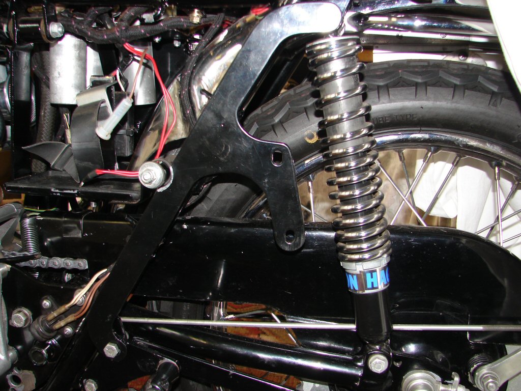
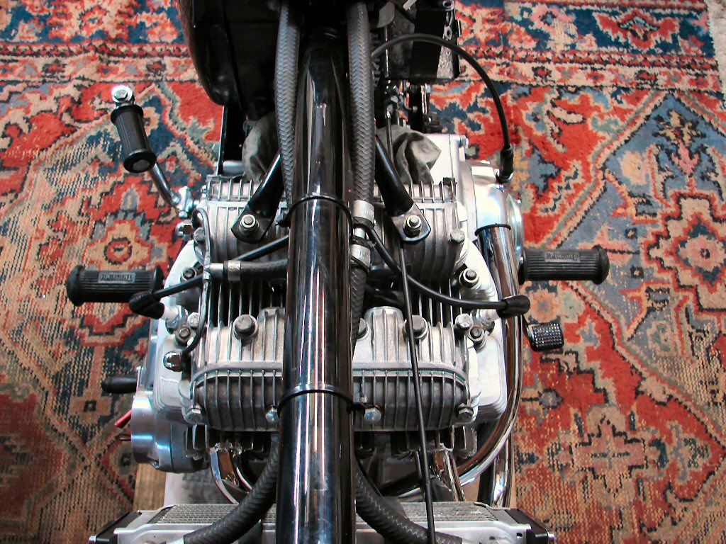
As the routing of the clutch cable on triples plays a big part in the ease of operation, I had been a little concerned how the cable might fare considering there would be some new hardware for it to contend with.
I need not have worried.
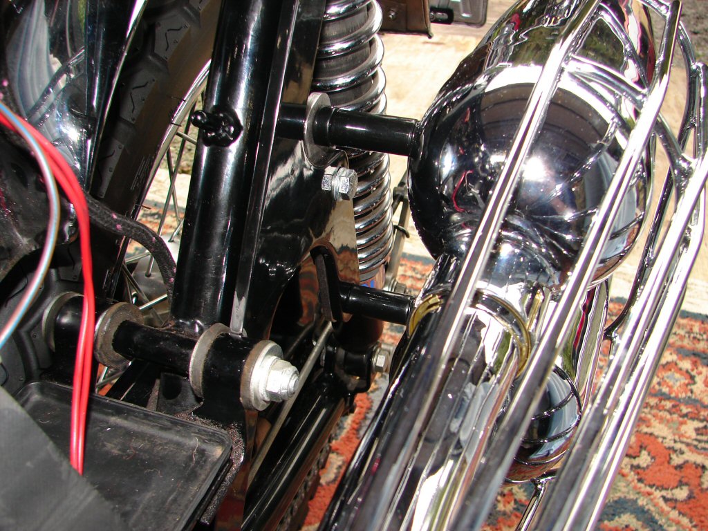
Perfect clutch cable clearance..
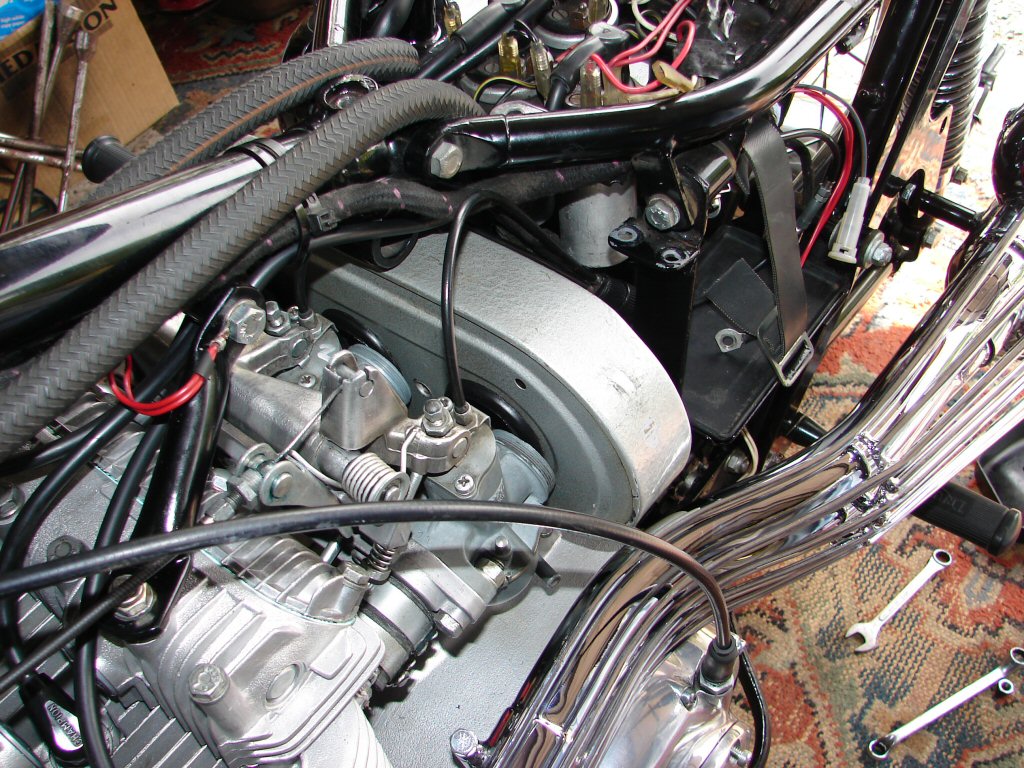
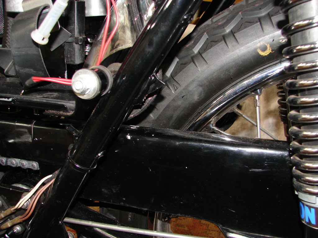
Less fortunately, it seemed that there would not be enough clearance for air filter, choke cable and lever, and the left side fuel line.
While these are considerations that can only be addressed as they come to light, they are not at all insurmountable, more a nuisance which will now require a number of new solutions.
From my perspective, I require the solutions to be elegant - inasmuch that they look as if they should be there, and are in keeping with the general appearance and age of the bike.
The next few posts will be devoted to how this shapes up.
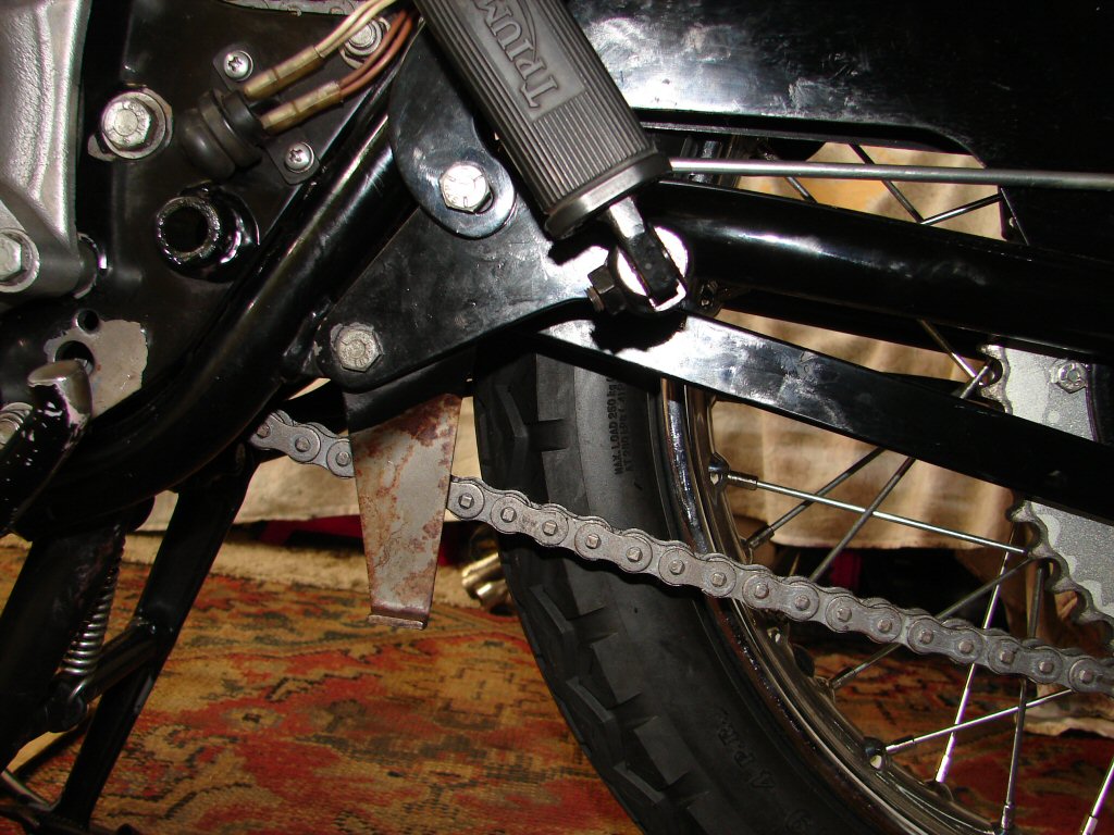
First consideration will be to remedy a number of issues concerning the carb assembly. The original air filter is just too wide to fit - in fact, I think it was just too wide anyway.
Secondly, the fuel lines are old and resist being bent, so they will be replaced with new line in rubber, and with some alterations to restore a fuel feed to the left side which was occluded by the new exhaust arrangement.
Assorted problems..
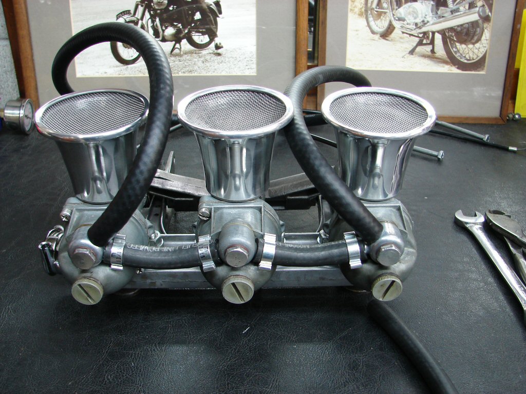
The proposed answer to the air filter is not to have one - but instead fit some gauze covered velocity stacks. The dimensions of same suggest a touch-and-go clearance is on the cards, and that has highlighted another annoying thing.
I can see why the T160 adopted allen screws for retaining the inlet stubs as a neater arrangement - but also these studs and self-locking nuts really make fitting the manifold rubbers a difficult matter, and in the case of the nice thick rubbers we now have - impossible even.
Just won't go that last quarter inch..
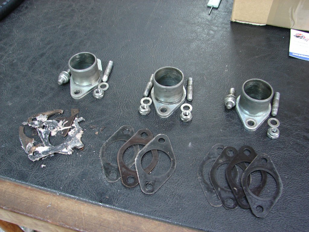
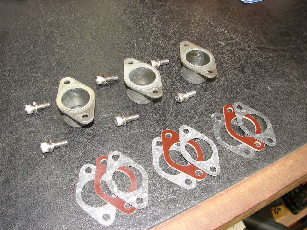
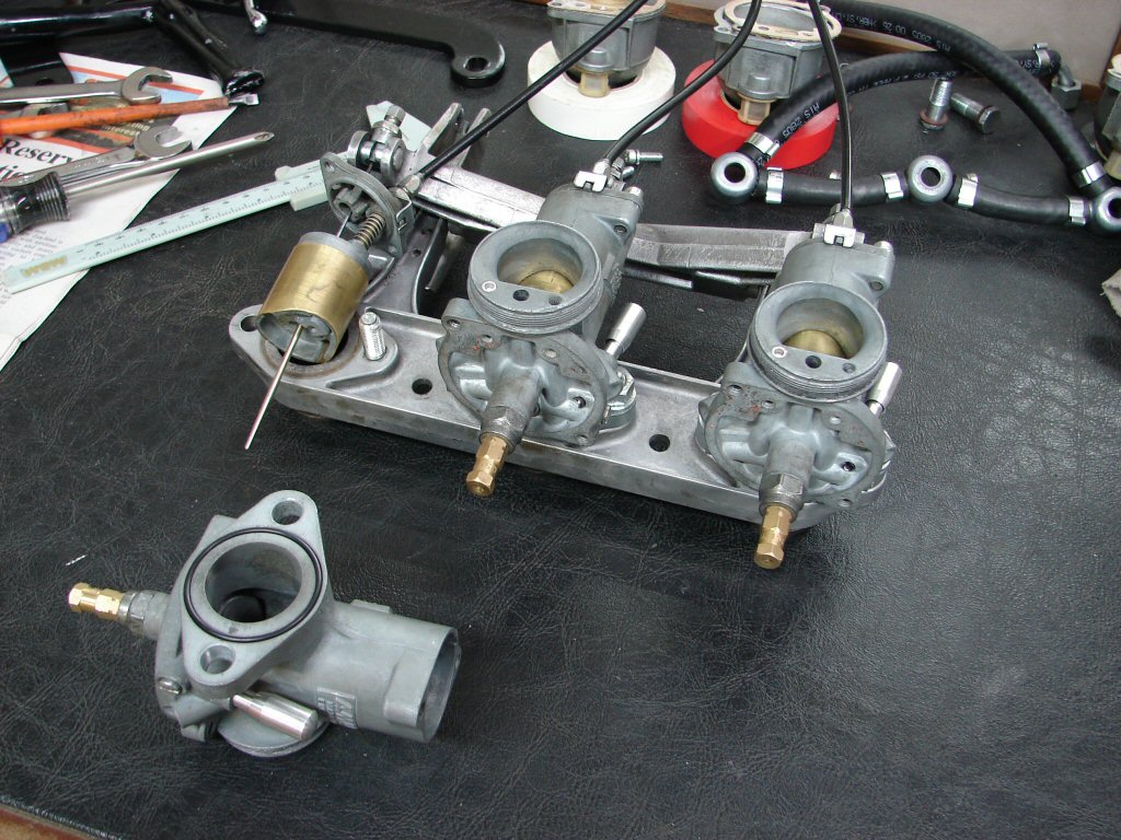
In order to remove the studs I had to remove all the inlet stubs. As it turned out - this was a rather fortunate thing. I would normally have left this area well alone, but having decided that this bike needed every consideration attended to, I went the extra mile. What I found were three inlet arrangements of which I would have trusted none to be airtight.!
I would not have previously thought that this would be a place that could allow an air leak into the inlet ports - but what I found tends to refute that. The right side had an extra gasket that has likely been there since day 1. Centre had the right bits, but both of these two had obvious signs of fuel inbetween the gaskets, so the seal was not too good.
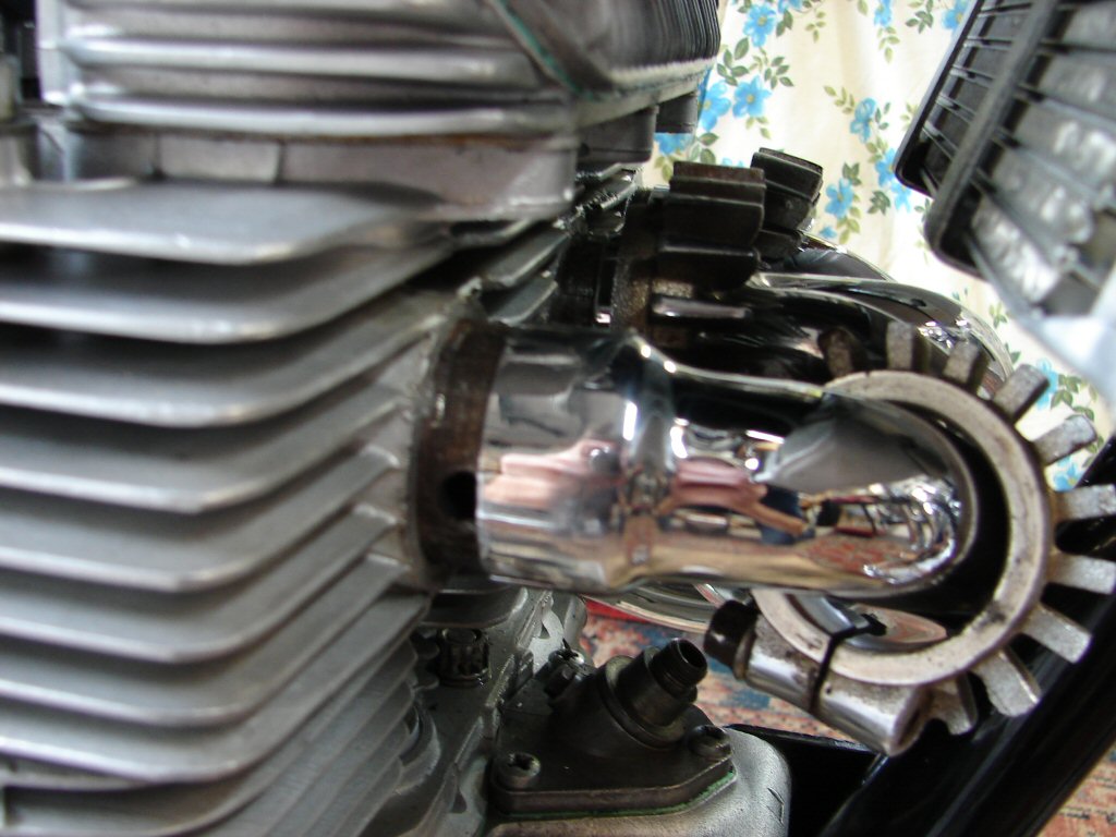
The left side was something else. I had noticed some signs of furriness around the edges of the gaskets which may be visible in the last photo, but in fact all the gaskets had totally broken down and had to be scraped off inlet stub and cylinder head. If there was in fact a correct tufnol heat insulator amongst this lot, it had disintegrated.
Chernobyl on No.1..
Annoyingly, this now creates another "waiting-for-parts" situation which is very frustrating - especially when you have a vast inventory of triple spares - but not these. While I cannot be sure that some serious over temp situation did not degrade the ok looking components on the right and centre into the crud on the left, I am very aware that in times past, when a rebuilder discovered a situation such as this, they did not, or could not, order the necessary parts from one of several trusty sources I now have. Instead, they "invented" a solution using parts they had handy - many of which owed nothing at all to the parentage of the machine in question. Many of these remedies managed to produce an ok result, but in many instances, returned at a later date to bite the backside of another owner who was not aware of the "temporary" nature of some previous repair. The only person you can trust is yourself.
Quality control is where the buck stops.
Suffice to say - a new set of heat insulators is on order from the nearest possible location.
Meanwhile, the next solution has promised to be a doozy.
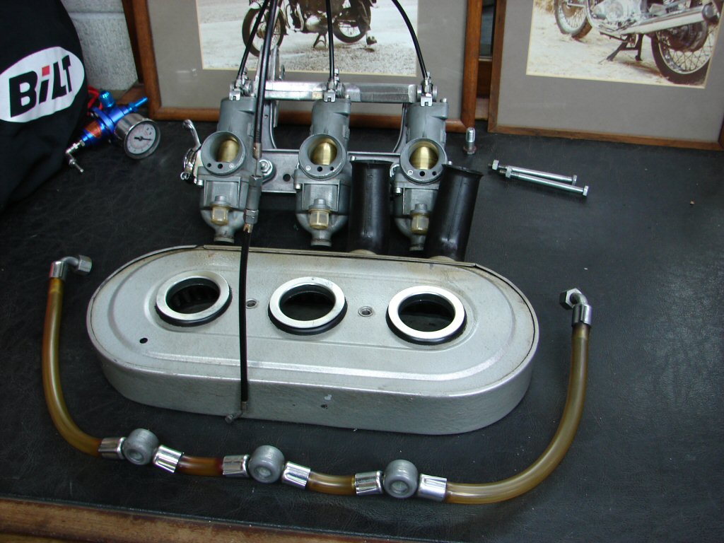
I have constructed a new fuel line arrangement using only the original centre banjo, and adopted a pair of new banjos that allow the lines from the tank to arrive down the inside route between the centre and outer carbs. This is possible because the seperate inlet stacks have much more working space around and between them.
I would never use stacks without at least a gauze filter, and in fact would much prefer to use a proper air filter medium, but the owner was happy to pursue this approach, and it has certainly proved to be by far the cheapest one.
The only "proper" filter that would likely fit would be a Mk1 Rocket 3 type with squared off ends, but having seen the ridiculous prices they are fetching I refuse to encourage that sort of price structure. Another option would be pod filters, but I think they look very much out of place on a bike like this, whereas stacks were quite common in the day and even today, so I consider them in keeping.
However, it may be possible to conceal some appropriately shaped filter medium within the large end of these stacks - which was one of my reasons for choosing them. They screw onto the rather crude threads on the inlet end of the Amals, although not well enough that you would consider them safe from falling off some time. Care will need to be taken to make them secure.
Some solutions are better than before the problem..
In another wonderful spinoff, adopting these stacks may even provide a cure to the choke cable/lever issue. Because there are now a number of alternative routes for the choke cable to follow, it seems likely that by moving the choke cable junction box to the right side of the frame spine, that there will be a way of holding the cable away from potential harm from hot exhausts and thus allow the lever to remain where it should be.
I think that with stacks instead of a filter, the chokes may become a tad more critical.
So, as you might expect, and unless my steel rule is bent, all of the inlet stubs were distorted on their mounting flanges. Just like the carb float bowls with their two diagonally opposed mounting points, these too have significantly warped and needed dressing to restore a flat surface. Whether this could create an air leak situation at the join to the cylinder head I could not say, but in future I will not be prepared to dismiss them as being above suspicion.
The new tufnol thermal insulators seem a bit thicker than those which were removed. That can only be a good thing as far as keeping the carbs and incoming air/fuel a bit cooler. The mounting holes on these examples needed opening up a smidge as they were not prepared to allow the 1/4" allen screws an easy path through. Never assume that new bits will simply bolt on - factory part or otherwise.
Allen screws are stainless items..
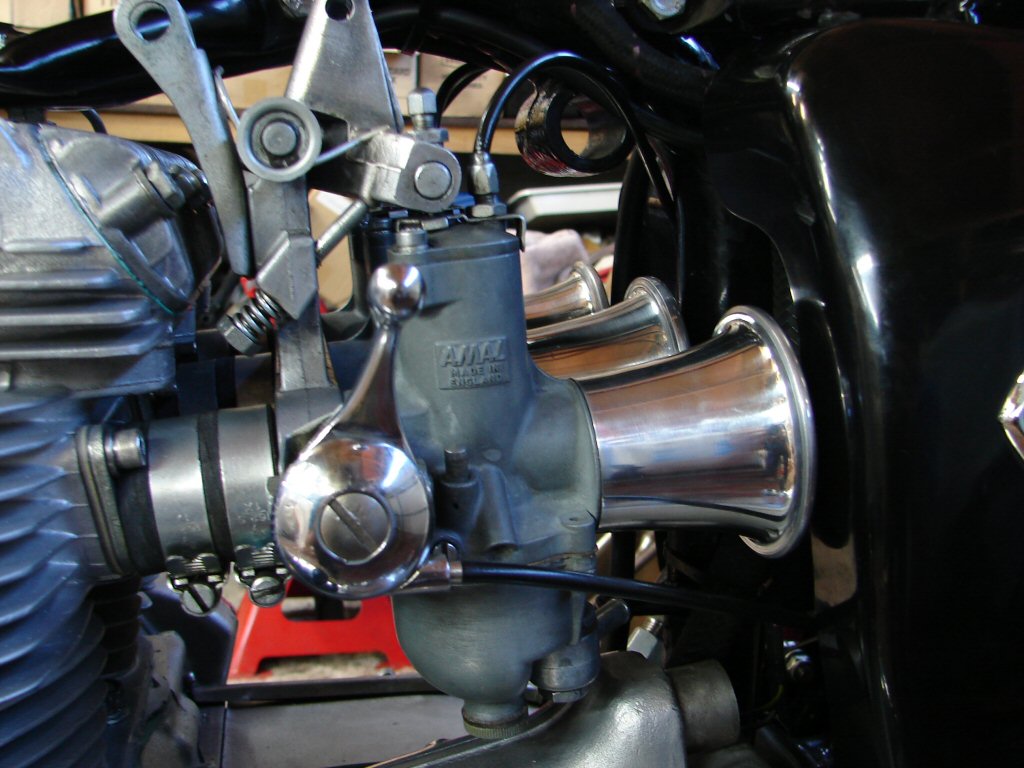
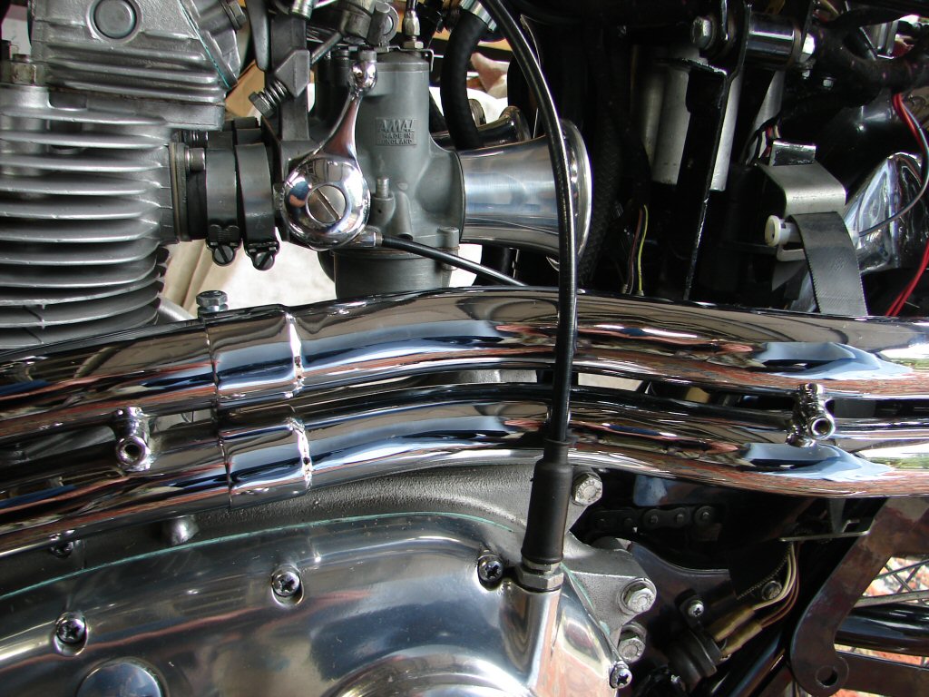
Pleasingly, it appears that the choke lever will be able to remain in its original location, as the cable has found a simpler path allowed by the stacks being much shorter than a solid air filter housing. Running the cable around the back of the frame spine has also given it a route which should keep it away from any excess heat from the exhaust.
The amount by which the manifold rubbers have moved forward on the inlet stubs makes fitting the stacks an easy task, where they previously could not be fitted at all. I will fashion some sort of support for the carb assembly as I believe that high frequency vibes on unsupported carbs can lead to fuel frothing. I also do not wish to encourage the manifold rubbers to emigrate as they can do.
While the outer end of the stacks are fairly close to the sidecovers and the frame spine I think that they will have access to enough air to avoid being effected in any adverse way.
This is another trial fit as I still need to attach the main fuel lines and investigate some form of filter medium within the stacks. The allens screws did all that was required as far as creating an easier fit and extra clearance. Cool.
This looks pretty good to me..
Next trick will be to invent some sort of filter medium.
So I did.
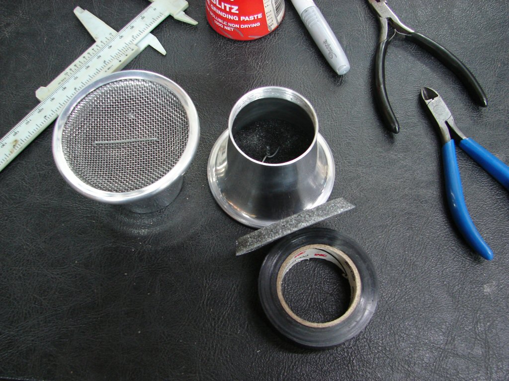
What fell to hand was some antistatic foam sheet which normally arrives as packing with computer mainboards. I fitted some over a stack while breathing through it to see how much apparent reduction in airflow I could notice. Not a lot - but definitely some. Worth a crack then.
I tried a test piece and also soaked some with petrol to make sure it was up to the task. All good. I now refined the size I wanted and marked it out.
Crop circles..
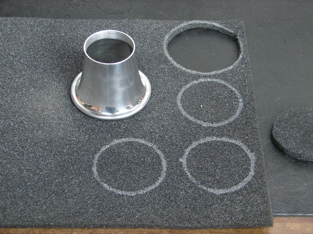
I cut the foam with a 45 degree or therabouts chamfer on the edge so it would fit more securely inside the stack. It fitted neatly but still would require some retainer to avoid the whole thing going down a nearby carb throat.
I figured the lacing wire approach would be an easy solution, and here is the finished article.
No more dust..
On the off chance that this will be a durable arrangement, I have cut several extra sets for future use. I would not bother cleaning other than blowing compressed air through them backwards, but they may become blocked by oil or whatever, so easiest to simply can the old and fit new.
Because there is now some semblance of restriction to the airflow, I will leave all carb jetting exactly as it was for now.
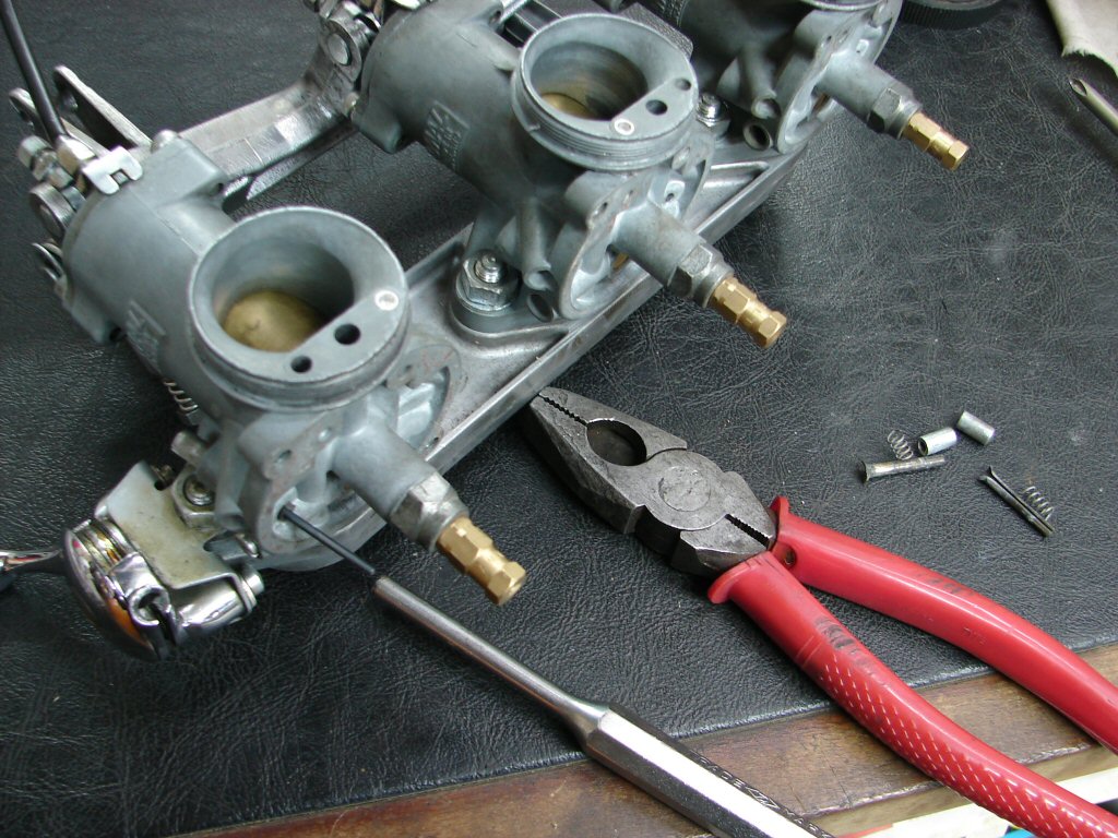
Today presented the umpteenth trial fit of the carb assembly. I had extracted the fuel tap hose connectors from the old fuel lines, and straightened them as required, so that the last missing pieces of the fuel line could be finalised. The stacks were refitted so that all the obstacles could be present in order that everything could be made to get along with everything else. This included seeing how the fuel lines and the choke cables would co-exist.
Quite a bit of traffic here..

There is a screwdriver supporting the centre carb in that pic, and the next job will be to organise a support bracket for the carbs which will mount where the original rubber mount was fitted for propping up the air filter.
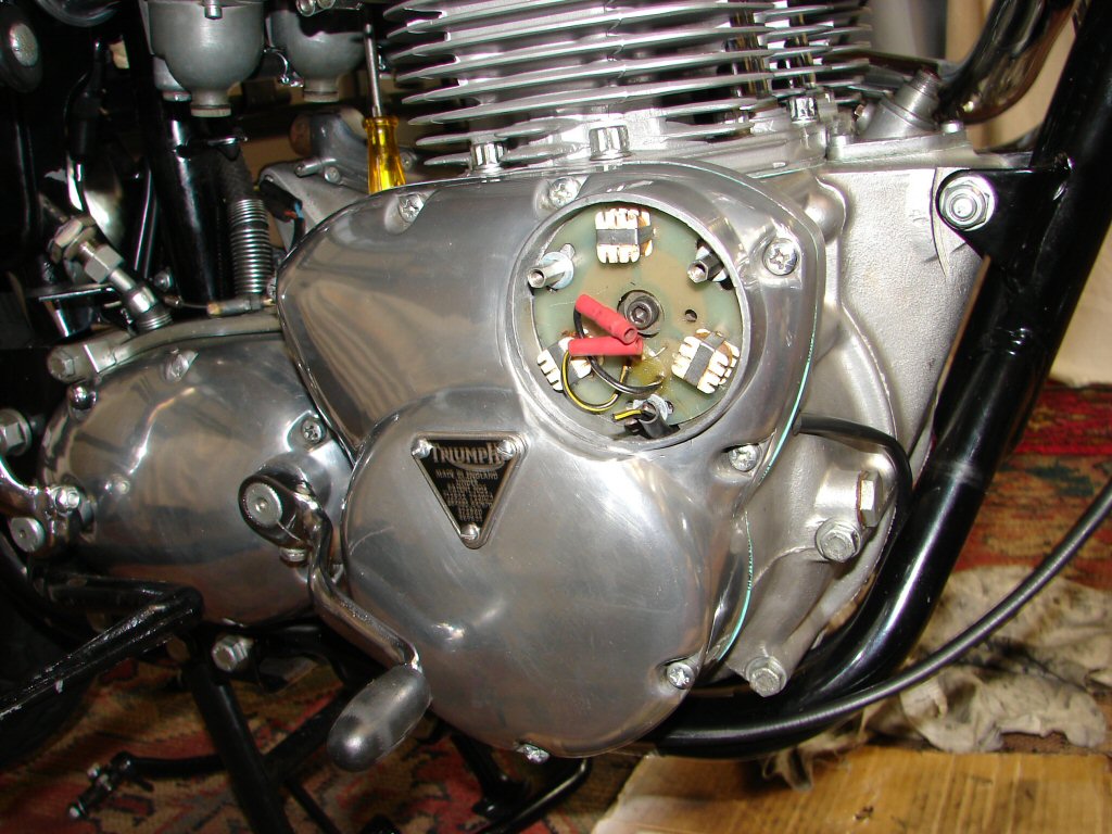
Last job today was to time the Boyer ignition and refit all its pickup assembly. As the engine was still sitting at TDC since my cam timing, I simply rotated the engine backwards by using the rear wheel with top gear engaged until the first drill mark in the crankshaft appeared through the handy aperture in the front of the crankcase arranged just for that purpose. Pleasingly, that coincided with one of the 'B' marks on the alternator rotor, and using the pointer screw I got that spot on. The Boyer instructions are easy to follow, and I positioned the rotor with magnets as suggested, and found the magnet screw head was exactly in the middle of the viewing hole with the pickup plate in the middle of its adjustment limits. Bodes well.
The Boyer is strobed for full advance at 5000rpm, and I never feel like doing that with an engine that has just lit up for the first time ever. I spend a little extra time getting the static timing as close as possible, then ignore it for the first couple of engine runs while I adjust the mixture before the exhaust headers go blue. In this instance, I will also be bleeding off fresh oil in the final attempts to flush any remaining particles out of the picture, so there will be plenty of hands needed on the end of my arms.
Just a couple of bullets required to complete connection..
Oh.
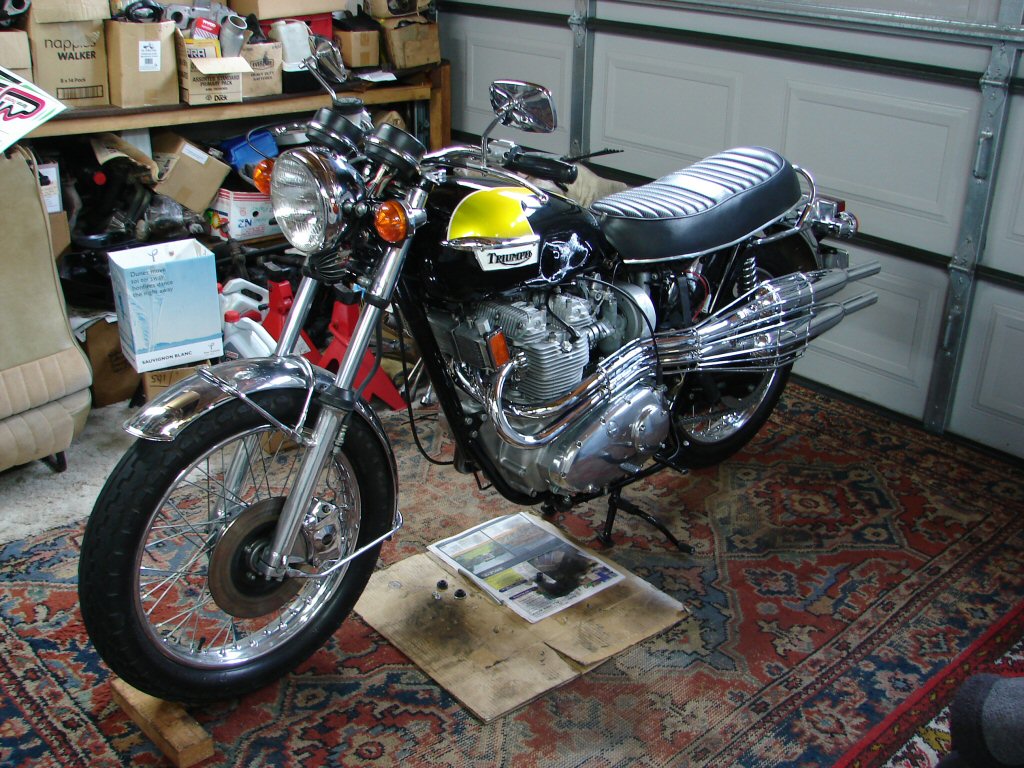
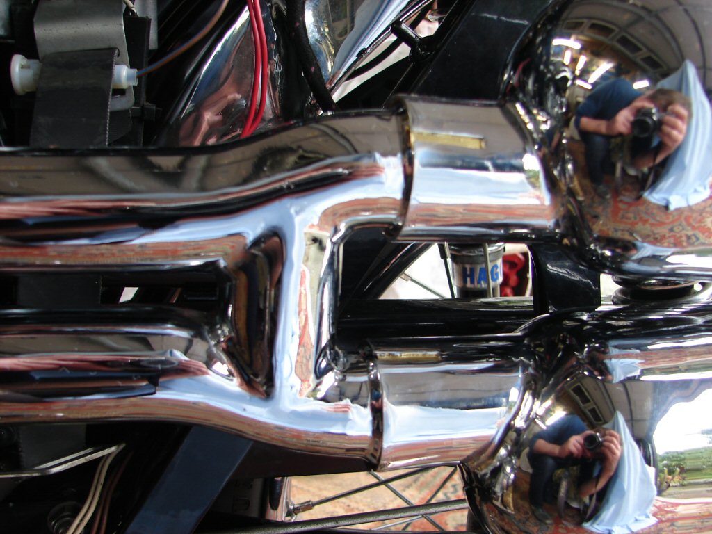
While I have alluded to it and shown glimpses of it, I have not yet shown a picture of the complete exhaust system. I have only trial fitted it once as yet, and that was to discover which bits would work with it and which would not. A fair bit of both really.
However - it is the need to incorporate this exhaust that is necessitating so many other considerations that we are all patiently enduring - so I shall now post a pic of the 'thing'.
This is a true 'one-off' and a huge amount of respect goes to the owner who commissioned it, and the reluctant builder who figured it would not work - but built it anyway because owner Mark would not leave him alone.
I think it is going to look fantastic, and it is much more inspiring in the flesh. Can't wait to see what sort of noise it makes. TR6C meets TR7C.
High-level of style..
A change of direction.
This is the interesting part of a rebuild - when new pieces drop into place and you shift your focus to a new area. It helps maintain a fresh approach to it all - rather than getting tunnel vision and imagining too much of the detail.
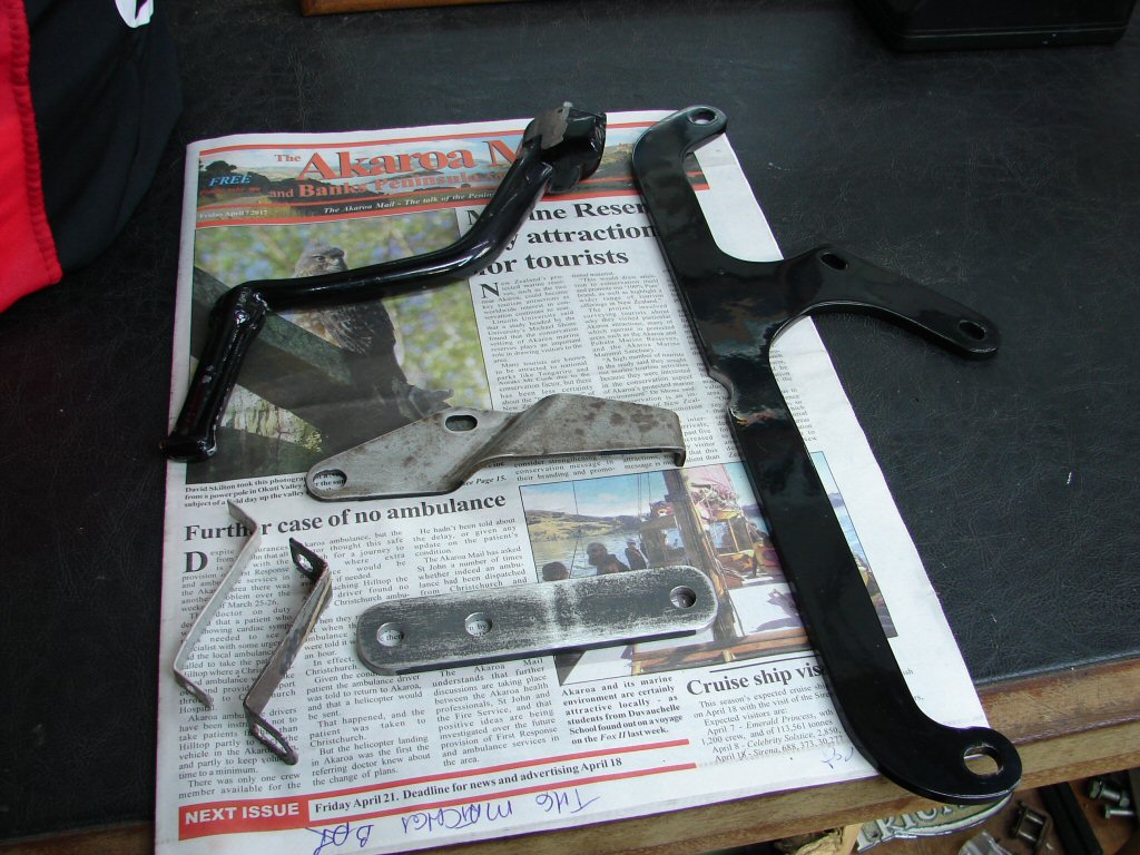
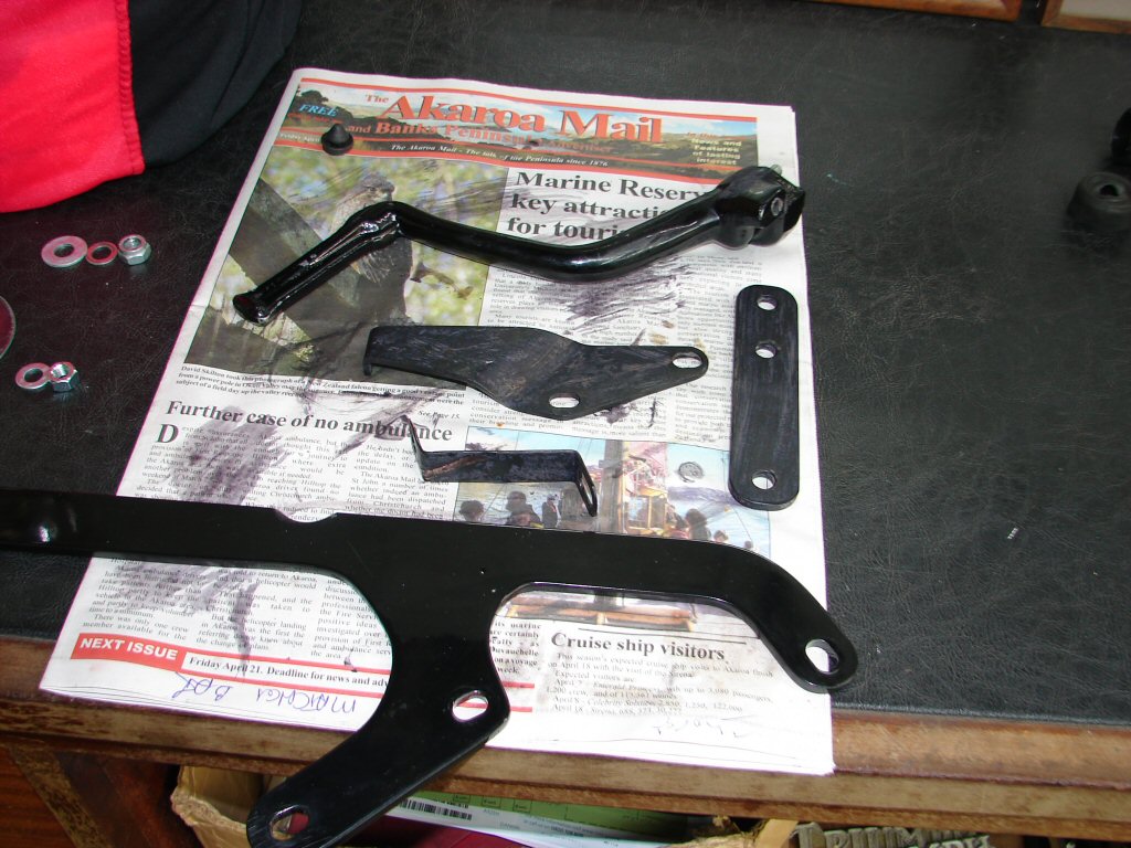
The beautifully made bracket whose purpose is to mount the mufflers in a bankable situation was in fact flawed. For no explicable reason, the mounting holes - or one of them - was entirely in the wrong place. Not only but also, there had been no allowance made for the battery tray mounting, which was understandable as the battery tray would have been absent on the basic frame jig on which the new exhaust was laid out. I drew up a simple bracket which would bolt directly to the existing one and introduce the correct mounting hole for the top muffler, and at the same time marked the area of the bracket that needed to be removed for clearance. I handed this to an engineering outfit who are agreeable to small and presumably annoying one-off jobs such as this, as they have all the basic stock for fabricating such things from, whereas I do not. They did exactly as requested, and phoned this morning to say it was all go.
In the right price bracket..
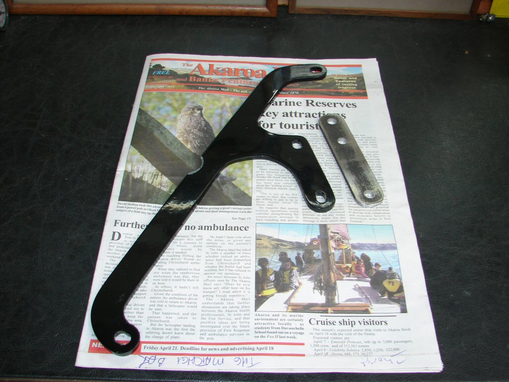
These brackets are fabricated from 1/4" thick steel - serious stuff - as is required here. The muffler mounts are the only support for the entire exhaust system other than the exhaust manifold, so understandably this rear mount needs to be absolutely solid, or the whole thing will flex and come loose.
The original supplied bracket mounts between the top rear shock mount and the top rear footpeg mount. With suitable clearance now for the battery tray mount it all fitted up perfectly. The new bracket will simply bolt to the rear of this bracket and supply a new mounting position that is about an inch higher for the top muffler. The mufflers are stock TR6C items and have staggered mounting bosses as an integral feature.
Suits you sir..
"Serendipity".
I love this word and its wonderful description of how things simply work out if you let them.
I have always had the extremely good fortune of being on the receiving end of such a fortuitous thing, but perhaps it is because I take great pleasure in it and am always the first to observe it. Ask my friends.. hahaha.
As purchased, this bike had suffered a not uncommon problem whereby one of the horn mounts had fractured off the rear subframe. The horns have some substantial weight and are spaced away from the mounting, thus placing more stress on it.
Ouch..
I had originally thought that once the bike was mobile, I would simply ride it to the workplace of my engineering friends and have the broken piece welded back on. During the trial fit of the exhaust system I realised that the mufflers would pretty much preclude any access to this particular area of the frame.
Now I can see that the new muffler bracket will provide the perfect mounting point for the missing horn. A quick trial fit proves that it is entirely possible, and it will just be a matter of seeing where the mufflers will have to be to ascertain where the horn can be. Choice.!
There will be a bit of paintwork required once all the mechanical requirements have been met, and I shall undertake that myself. There is another existing bracket which has always offended me by being only partially painted, so that will also get the treatment. Its purpose is to provide a resting place for the main stand when retracted. I am not sure if it has always been there, or has been invented as a cure for a problem. Either way, it will get a nice new shiny coat of paint and become part of the master plan.
Don't want no rusty bits..
The weather forecast for this easter weekend is not exactly conducive to painting. We have the remnants of a nasty cyclone threatening to inundate much of the country - but I suspect that there will be some small window of opportunity during which I can apply a coat or two of shiny black finish.
We shall see.
Easter weekend 2017. Decided to stay home this time around and get numerous things done about the homestead. The tail end of cyclone 'Cook' came through on the Friday - so, knowing I was going to get wet anyway, I went out and washed all the windows on the house. I decided it was one way to turn a minus into a plus.
It was not until the Monday that I got a chance to return to the garage to see if I could manage the same approach with the horn mounting on the muffler bracket. I bolted all the exhaust system up for the second time - although the bracketry was now all complete and in the right place.
Several things became apparent.
Although it would be possible to mount the horn on the muffler bracket, it would place it rather close to the mufflers. Also, it transpires that the bracket was made with the original location of the horn very much as a part of the design, and the nice inverted curve above the chainguard frames the horn perfectly when in its original position. I simply have to honour that degree of attention to detail by restoring the orignal horn mounting in some way. I shall return to that later.
This fit of the exhaust would need to be the final trial, so I needed to take care of any issues that were going to be problematic during the final approach. There were a couple of things that would be headache material. The pipes were slightly too long, which meant that the mufflers would end up overlapping the nicely filled radius ends where the mufflers should have been clamped.
The bug trap top..
The mufflers as supplied were a very loose fit on the pipes. Also, the supplied clamps would not even fit over the ends of the mufflers. I took this to mean that the mufflers in question were possibly a bit out of expected tolerance. I had on hand another pair of clamps that were a perfect fit on the mufflers, but would hardly be able to compress the ends sufficiently to make an effective joint. I cut two inch wide strips of .010" brass shim and fitted them inside the ends of the mufflers, which now agreed to become a close sliding fit on the pipes.
It appeared that my mods to the muffler bracket would be adequate as everything had bolted up reasonably happily and looked visually correct.
Oh yes - the battery tray mount..
I had previously noted that the nut extending from the battery tray mount was causing some grief to the side cover during fitting and removing. It seemed that reversing the bolt so that the head was at the outside would not only improve clearance, it would be a lot easier to remove it should one ever feel the need. Again. I could also see that the inner rubber bush assembly had been assembled in the wrong order. It seems rather perverse that people would throw immense time and money rebuilding a machine like this then fit things the wrong way round.? Oh well, shall add that to the list.
On the down side of the exhaust fitment was the fact that the headers had come away from the cylinder head during the bolt up process. A lot. The tail pipes end up heading away from the line of the frame, and forcing them in so that the mufflers would bolt up had sprung all the headers off the exhaust stubs to a degree that would be hopeless. It would seem now that some shim may have been required in the headers as well, but as they cannot be removed from the stubs without lifting the head I shall see if there is any other way to make them comply.
Leaky pipes..
I placed a wooden wedge between the headers and the frame downtube then bent the exhaust tail pipes inward as far as I could, holding the weight on for some time. I am not sure if anything moved, but it may have introduced a slight deviation where the headers clamp inside the tail pipes. They are a very firm fit without the clamps being tightened yet, so any small degree of offset might take some heat off the manifold end. No pun intended.
I would also like to convince the tail pipes to move a little further forward on the join, as that would ease the position of the muffler to tail pipe join, but as you can see, the two bosses which retain the heat shield are placed one either side of the join, so there will not be much room for manoeuvring here either.
Complex curves..
On the overdue good news front, the choke lever/cable system seems to have enough clearance as hoped. Carbs are nearly ready to be removed again for fitment of some oversize ticklers, as they do make life a lot easier and the gloves do not suffer as much petrol ingress. One of the jobs today would be to fashion a support bracket for the carbs in lieu of the original air filter support. After that they can come off for the final (hopefully..) adjustments before going back on for good.
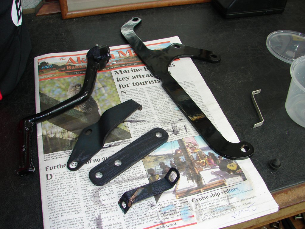
In one of the boxes on my workshop shelves is an assortment of useful bits of steel and alloy which have been saved from various sources. They represent what I perceived as being worth storage when they came to hand. Today I decided that a particular piece of steel that had broken away from the filler/dipstick tube on a Borg Warner 65 auto transmission might be persuaded to provide some reliable support to a bank of Amal carbs which would undoubtedly fall off if such a thing were not present. I had fashioned a basic sample of what was needed from a small piece of alloy which was thus easy to shape.
I have a cunning plan..
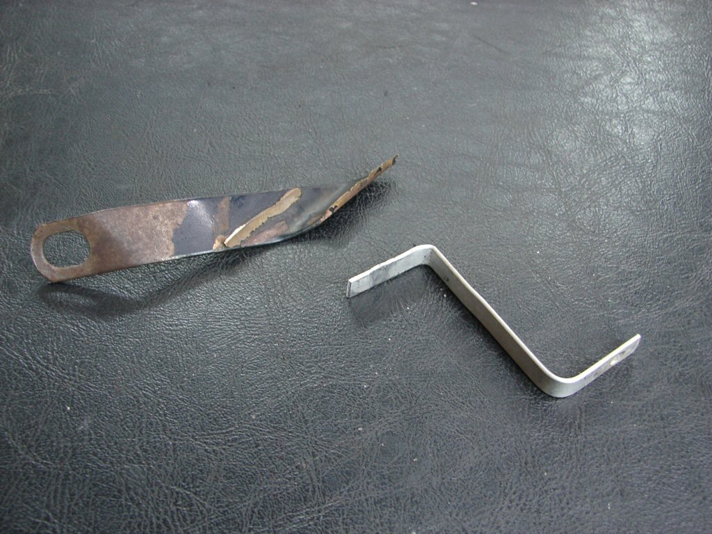
First task was to flatten the scarred relic out and grind off the fractured bronze. A quick comparison with my potential design then showed that my volunteer was too short, so I introduced an angle to the centre part of the bracket to reduce the amount of steel needed. This looked as though it would do the job, so it became plan 'B'. The original rubber buffer from the old frame support was removed and a hole provided at the top end of the new bracket where the buffer would now directly support the inner end of the stack on the centre carb. The buffer would also press against the rear of the float bowl, thus preventing the carbs from migrating rearwards.
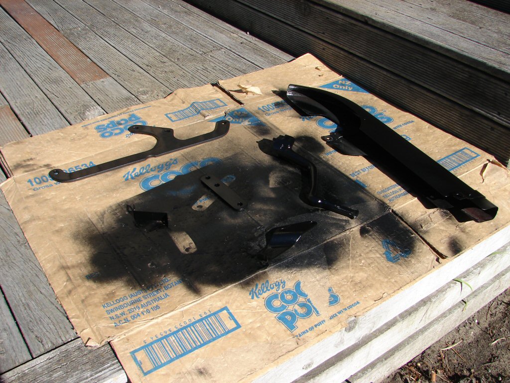
I now had a number of parts that would require painting. I had removed the mainstand rest bracket and found that all of its powder coating was simply flaking off, so I removed all of that coating then sanded the whole thing to get rid of the rust that had prevented the powder coat from bonding to the steel. The muffler bracket had a small area ground away to encompass the battery tray mount so that also needed paint. The new muffler bracket which was added to the mix was bare steel and would need a serious coat of paint. The right side riders footpeg was found to have been interacting with the inner primary cover, as the latter was from an earlier model and somewhat bigger around the engine mount area than what should have been fitted to this bike, so I ground the footpeg mounting boss down to provide clearance.
All of these parts needed paint and were now ready to receive it.
Brackets for the masses..
My 'one-size-fits-all' paint of choice is engine enamel. It is in aerosol form, applies easily, dries quickly, resists high temps and has proven to be very durable given time to cure. It does require some reasonably dry air and moderate temp to spray properly, so today was not adequate. However, there is a precursor which I was able to begin.
I use an acrylic product which is a rust killer, but also acts as an undercoat. It is surprisingly tough when you try to sand it, and that is a good sign in my mind. Although white in colour it changes to black/purple when reacting with steel - especially steel with rust. I figure all bare steel has rust, so this is a necessary first step regardless. It does not seem too particular as regards ambient atmospheric conditions.
Slow progress..
When this is ready - tomorrow - I will coat the other side of all the parts that need it. After that we wait until there is some faint vestige of warmth so I can apply the top coats.
Ok - that didn't happen.
Instead I removed the carbs to fit the extended ticklers. I was hoping to be able to do this without disturbing the carbs from the adaptor, so I removed the fuel lines and banjos, then removed the float bowls.
A 5/64" drill bit is a handy drift to pop the tickler button off the top.
Takes a solid whack..
When fitting the extended shaft for the new innards the only real consideration is to get the holes to line up. This allows the fuel to exit at the original height.
Of course - if it fails to line up you simply drill through the outer hole and the new tube using the same drill bit.
I pour a quantity of boiling water through the hole in the carb body to heat it all up before drifting the new tube in as far as it will go. I figure it removes a bit of stress.
A suitable flat head screw protects the top edge of the new tube while drifting..
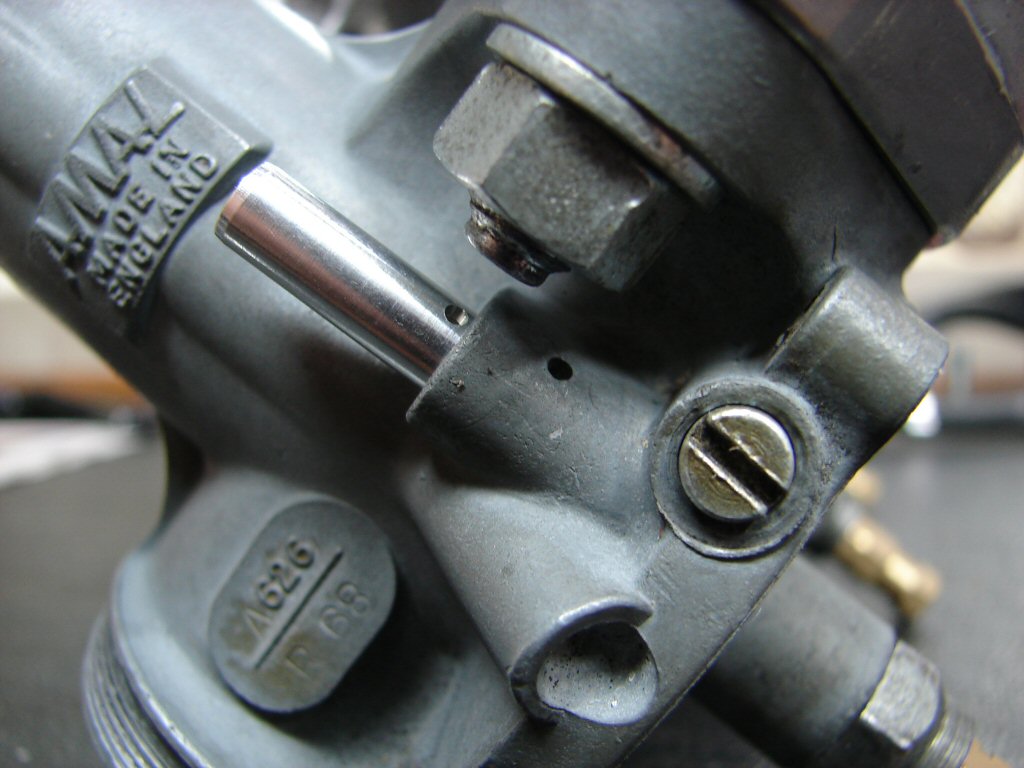
Having fitted all three new extended tubes I discovered that the new buttons were a very reluctant fit and I would need to use the vice to press them on. This meant the carb bodies would be best removed from the adaptor. I did so by removing the tops first, thus leaving the throttle settings and choke cables exactly as they were.
I then discovered that the o rings between carbs and adaptor were somewhat aged, so were in need of replacing. I faced the carb mounting surfaces first with some fine sandpaper and happily found them to be very close to flat, so the new o rings were all that was required to achieve a nicely compressed seal as each carb went back on the adaptor.
Sensible mods and necessary new parts..
This was close of play tonight, so easy reassembly left for tomorrow or whenever I next get to it.
Yes - the carbs all went back together with consumate ease. However, they cannot be fitted until the new support bracket is ready, so the preparation of that became highest priority.
I completed the undercoating process with my rustkilling primer. It applies as a milky white thin coating.
No more rust..
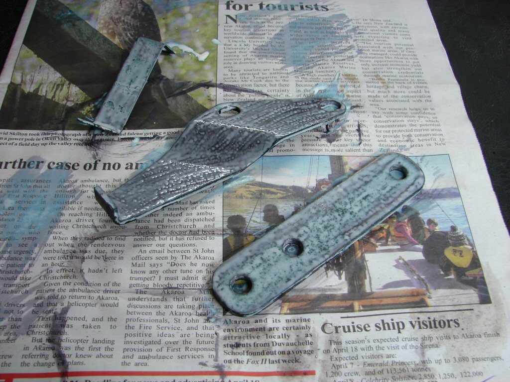
By this afternoon that coat was dry and all my bracketry was ready for a top coat. Ambient temps today were nowhere near spray paint friendly, so that was not an option.
The forecast predicts 18 degrees C tomorrow, so that would be a very timely thing if it comes to pass. All these parts could be new and shiny tomorrow.
Waiting for the sun..
Next consideration is to weld the broken horn mounting back on. I do not have a welder, but I do have a very competent panelbeater less than a block away, so I shall be looking for him tomorrow.
As this step is necessary before any of the other parts can be re-instated, I decided to prepare the bike for welding even if it has to be taken elsewhere. In the interests of minimising damage from welding splatter I removed nearby wiring, plus the chainguard. I included removal of the left rear shock absorber simply to make access easier. I also note that the chainguard has a number of scars in its paint finish, so shall add that to my group of items needing paint.
Prepped for surgery..
Being now somewhat stuck in the mode of needing other conditions to be met before continuing progress I looked around for another problem that I might attempt to resolve.
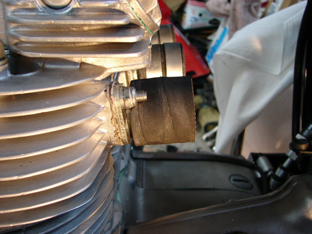
One showed up. The crankcase breather. This previously connected the crankcase to the air filter, but the air filter has been superceded by stacks that do not encourage any form of fume disposal. Time for a new approach.
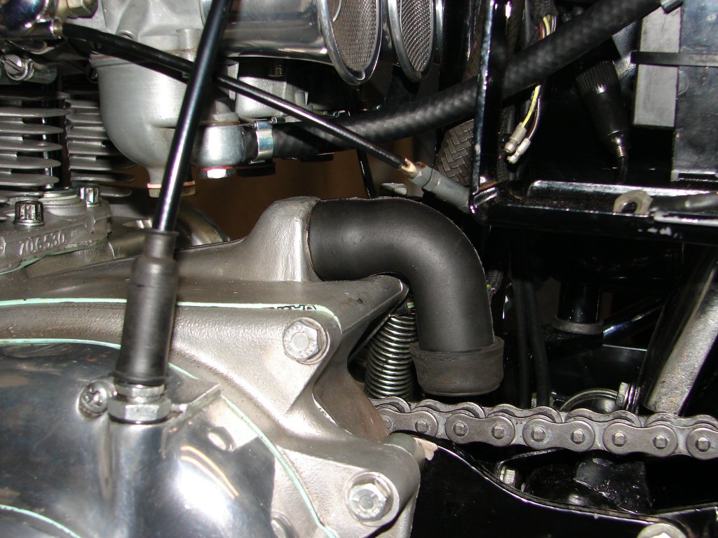
I decided to adopt the "minus into a plus" approach, and to rotate the breather hose 180 degrees and vent it onto the rear chain. I figured that some form of restriction would help to contain any excess enthusiasm that the breather might have at some time in the future, so I looked around my odds and ends for a suitable thing to achieve this.
I was thinking of a rubber item that might be a push fit onto the end of the breather hose, and what fell into the trap was a dust cover from a brake wheel cylinder kit. Much as I hate to destroy any original item, this seemed to be a necessary manoeuvre. I checked my usual suppliers for another breather hose that I might sacrifice, but their items looked better than the one that came off the bike, so I decided this would be the sacrificial item and that a new one could be purchased at a later date if needed for a return to standard.
Strange bedfellows..
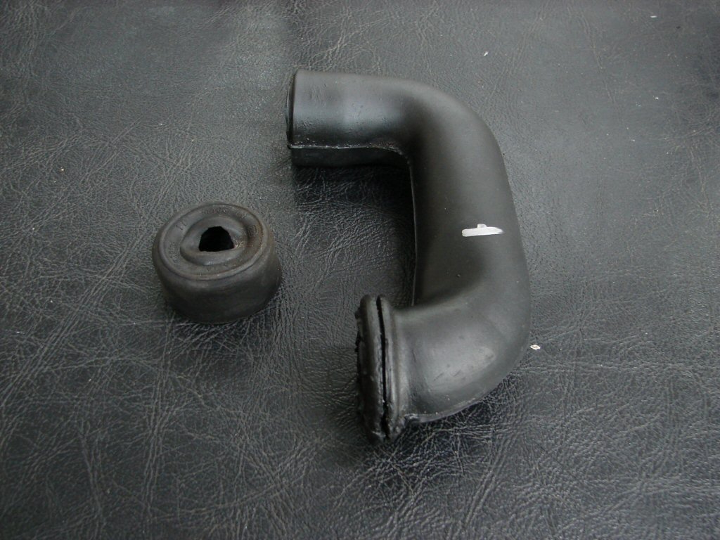
The mark on the breather hose is where it will be cut. The dust cover promises to be a neat fit over the cut end. I trust the force is with me..
Happiness is - painted things drying in the sun. Actually - considering the volume of rain we have enjoyed(?) this autumn, just seeing the sun is a pretty happy thing all on its own.
There will now be a few days of paint curing time, so I am not yet sure whether it will do as-is, or if it will need another coat. I also painted the spring adjuster on the removed Hagon shock absorber. I think Hagon shocks are terrific value for money and am happy enough with my own - but as they are not sponsoring us we shall not be giving them free advertising - but a return to black paint as opposed to alloy. The gloss paint did not look right on the shock, so it will get another coat of satin instead.
Black is the new black..
In other news, I tracked down my panelbeater friend and he is happy to sew the broken bit back on. That cannnot happen until Tuesday next, so progress will be pretty much halted until then. Nothing can go back on the bike until the horn bracket is in place, and I had always been aware that this was going to be a sticking point. At least I will only have to wheel it a couple of blocks.
I guess this will give me ample time to complete the painting of the ancillaries.
So thats nice..
The weekend. A time when I might be able to utilise the help of another. So I did.
I was aware that the footpegs were not quite straight. Having used a little cutting polish on the recently painted left peg and fitted it, I could see that one peg was bent forward and one back. Only slightly, but it still aint right.
A bit askew..
So here is the - waiting for patent - Kilroy method of peg straightening.
You take an 8 foot long piece of 2" galv pipe. You place it over the errant peg - which has had a piece of rag wrapped around it to protect the paint. You get an accomplice - willing or otherwise - to sit on the bike so it doesn't wander off, and you simply bend the sucker. The leverage afforded by a pipe this long makes it a total breeze to control, and you can bend it to any position you want. I chose directly at right angles to the frame but with a slight upward slant.
On a bender..

So - now we had two footpegs both aiming in the right directions, so some new rubbers would be in order. You may remember that the first one I tried split in the process.
The first pair of peg rubbers I was supplied looked quite different to each other. One was flexible, looked like rubber, smelled like rubber. Not sure of the taste. The other looked decidedly different. It had a shiny appearance, was not very flexible at all, the moulding of the logo had not gone at all well - frankly I am a little surprised it was supplied as a supposed pair to the other.
Rather than return it overseas I simply purchased one locally from a supplier who recently provided me an excellent pair for a Bonneville. This one turned up looking proper and is the lower one in the photo.
One good rubber here..
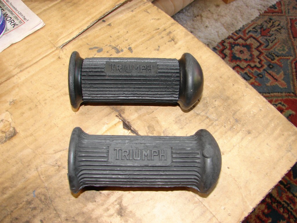
Both rubbers now fitted without drama. I use a little WD40 to ease the entry, and press the outer end with my knee while twisting the inner end with my teeth.. aaah.. hand.
They complied, were a firm fit of course, but neither exhibited any difficulty and slid completely home.
We been pegged..
I now realise that neither my panelbeater or I had remembered the fact that Tuesday is Anzac day, so I am thinking that there will be no welding done that day.
No doubt I will find something to be going on with.
Working on the assumption that any small thing you do in the direction of progress ensures that you are making some, I filled in another blank today.
Now - I have always owned British Motorcycles, but I have also owned Italian and Japanese versions. However, I think it must be the part of me that most relates to British bikes that allows me to get excited about this picture.
Yes - it moves me another step closer to the completion of the project in hand - but it is also a little sad.
I just love the look of these..
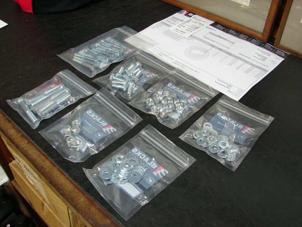
That is what $34 worth of new UNF stuff looks like. Why only get two or three.? I am particularly happy with the washers, as they are true to the original dimensions of those used on this bike and many others of the period. Should cover me for a while.
Still cooling my heels waiting for the small but necessary welding to take place, but managed two small items today.
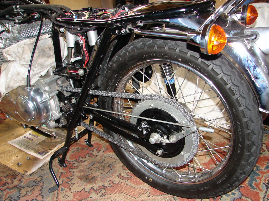
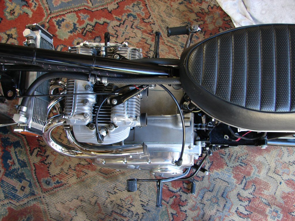
Carbs went on for what I trust will be the final time. Stacks secured with silicone as being somewhat vibration resistant. A close eye will be kept on their continued security.
Normal aspiration..
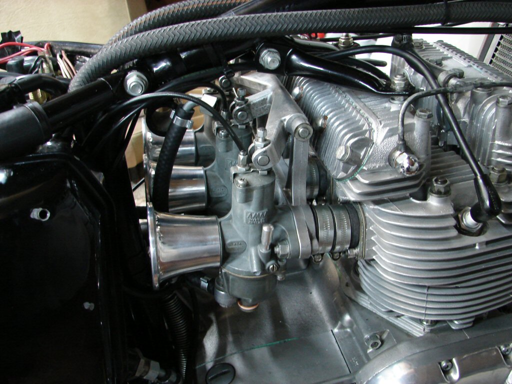
The recently painted carb support bracket was pressed into service and seemed to adapt to its new role without complaint.
Original rubber buffer from the air filter support is fitted in the far end and shaped with a furrow so as to remain located beneath the centre stack. Bracket is of course mounted where the buffer previously was.
Visible support..

The other fitment was the engine breather with its slightly restrictive end - also secured with a smear of silicone sealant. The cup on the lower end is a firm fit and has an internal lip which makes it reluctant to come off even when coerced, so I left it as it was.
This part needed to be fitted about now as its location will become somewhat obscured as soon as I begin refitting all the parts that have been waiting for paint or the completion of the welding of the horn bracket.
Just rubbery..
Tomorrow promises to allow two processes to move forward. Weather man predicts 20 degrees C so I might finalise some paint, and Andrew the panelbeater thinks he may have some time for my small welding job.
That would be ace.!
Well - it was inevitable - time for Part V.