The continuing restoration of "Trevor"
Part II.
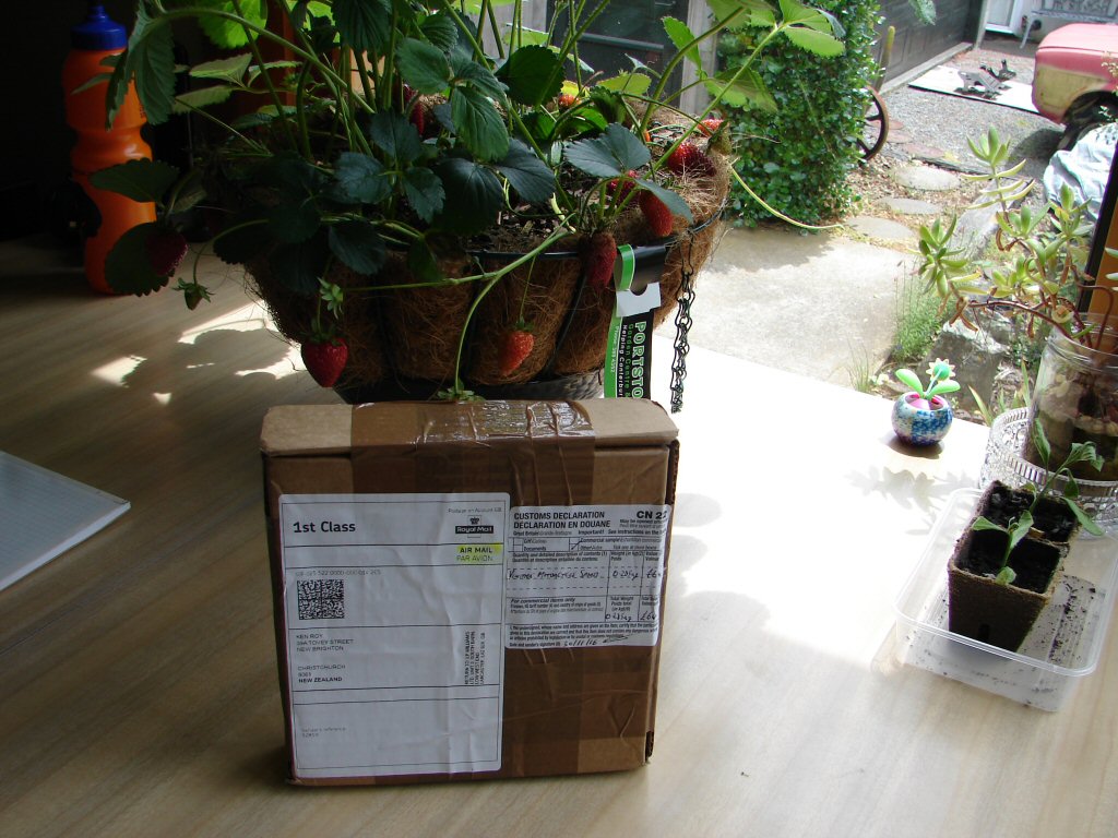
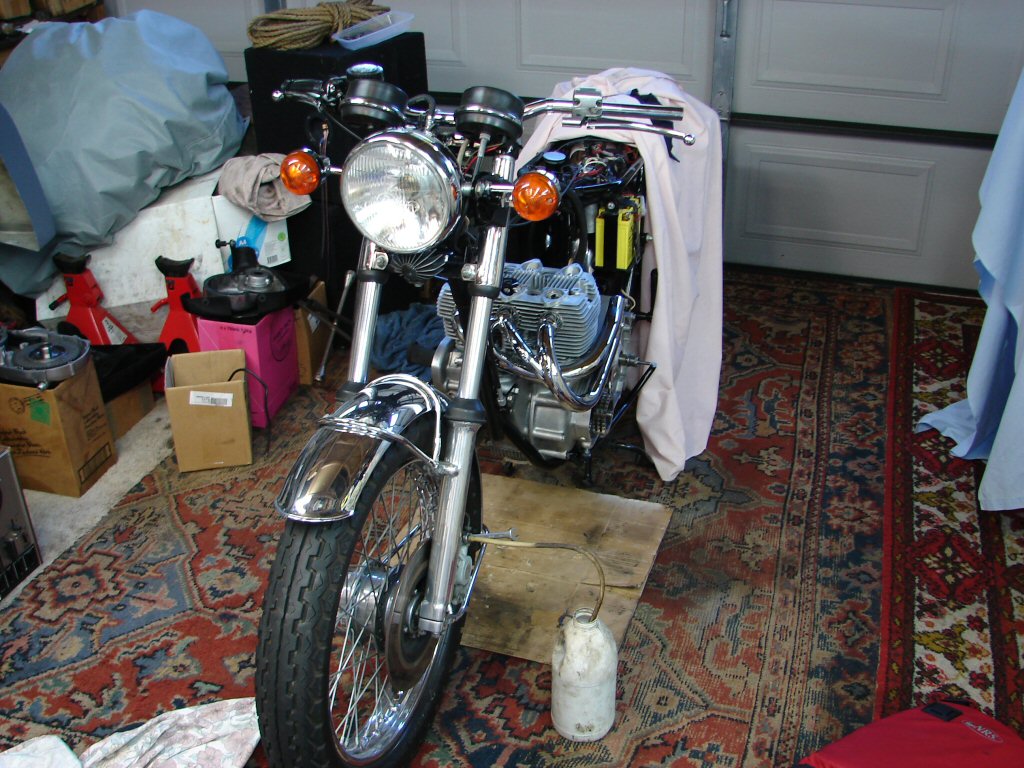
There is a visual clue in the last photo as to a rather unique direction that this build will finally take. I am not going to spill the beans at this point, but I believe it will make this bike a true one-off. I hope it turns out as well as it promises to.
All will be revealed.
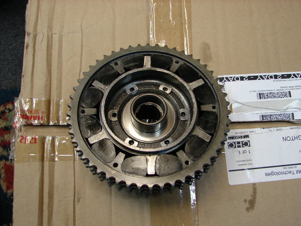
There is never a bad time to receive good news. The inside of the shock absorber looked to be in great condition. The cover plate was a bit gritty from what seems to be previous attempts at removing it with sharp objects. Simply tapping the opposite side achieves this, so it is a little sad from two directions - one that it was felt necessary to prise it apart - two that nobody made any attempt to clean up the damaged bits.
So I did.
Meanwhile the new locking tabs are in flight somewhere around the globe.
A rare sight when opening these up - good rubbers..
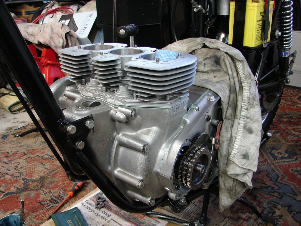
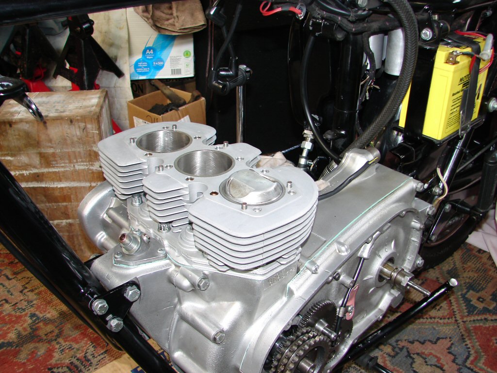
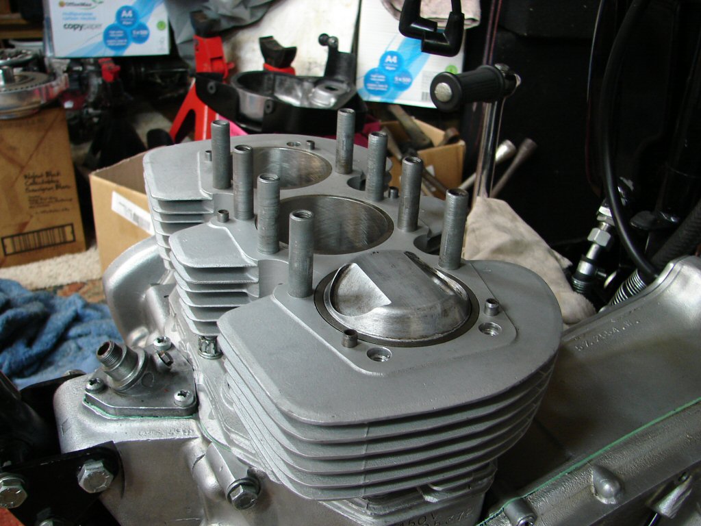
I decided to trial fit the barrels. These were a replacement item, so had never been on these crankcases before. There was a slight problem with both areas where the locating dowels are fitted. On closer inspection, it was simply due to old sealant that was lodged in the stud holes. No big deal to clean it out with a drill bit by hand - but it would have been a real bitch if the barrels had already been fitted over newly ringed pistons.
These barrels were a real find.
Thanks to the vagaries of xmas mail deliveries it has been an enforced break in proceedings whilst awaiting critical parts. I could have made progress in other areas, but I wish to follow one line of inquiry to make this more straightforward to the onlooker.
Seems the ball may be back in court..
Even though it has only been a little over a week that progress ceased - it always takes extra energy to pick up the thread as it were. I decided to start somewhere easy and gap some rings.
I checked both at the top and bottom of the bore and was happy to find no difference, so the rebore was well managed. The bottom has that nice taper though - so more user-friendly to continue that end. Looking for a minimum of 8 thou" and finding just that. Cool.
Curved feeler gauge from setting Trident valve clearances..

In a logical sequence, rings are now applied to pistons. Oil rings first then the two cast compression rings which appear to be identical - and happily have 'top' marked, even though a taper on their inside top edge makes it possible to determine as well.
The oil rings that came with this set are 3 piece with two thin scrapers and a spacer. I have always found these type to be very effective at controlling oil, though they most likely add a bit more friction in the bore than cast type. Whilst I hear that the latest cast type are getting good results, I would not have trusted them in the past.
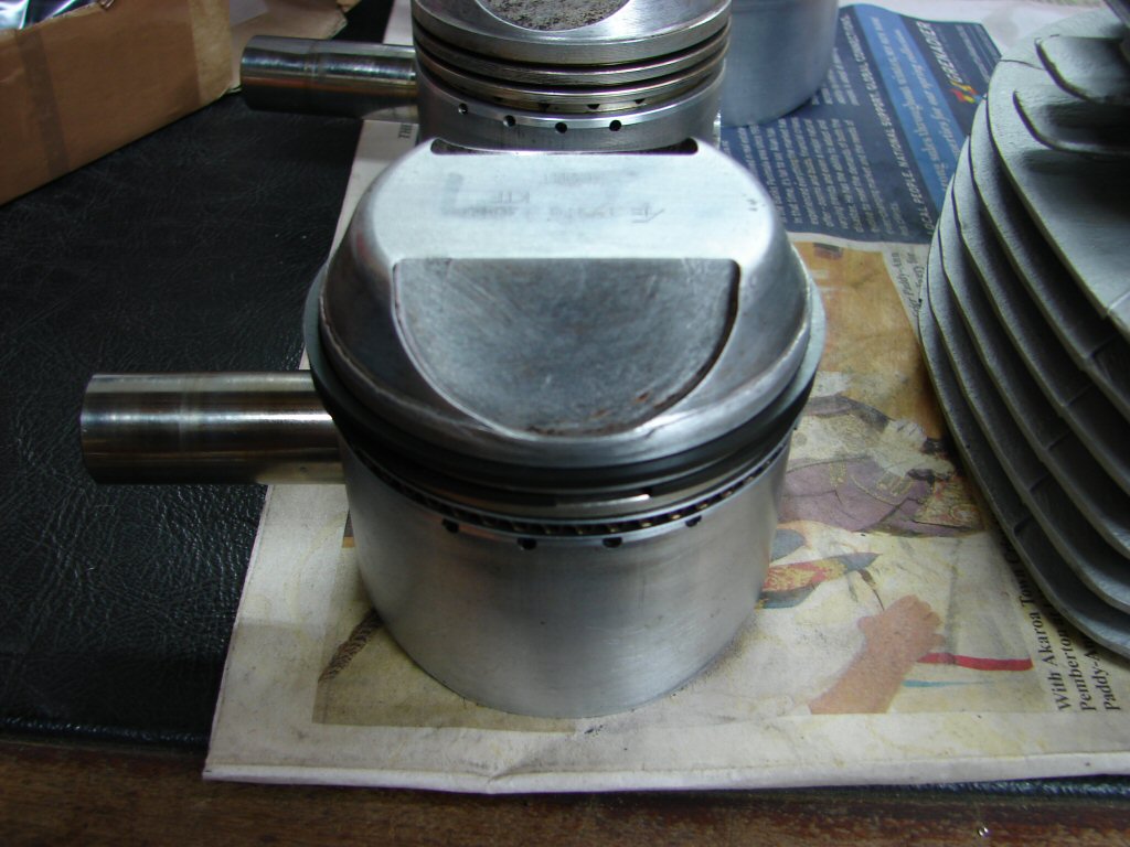
Despite the blurry picture, it is visible where the top edge of this piston made contact with the cylinder head when the conrod broke. I have yet to repair the head.
Circlips already fitted at the tightest side of the pistons.
As we are blessed with a parallel universe I shall now digress.
Because I can...
I am unsure as to why my machinist of choice told me I would need to drill out the oil tank filter to match the new enlarged oil feed pipe. I did - as you have seen - but then realised that I would require a larger top oil pipe and oil line to suit, so I duly ordered one of each. Both are standard T160 parts. When they turned up it was immediately apparent that the larger oil pipe would not fit into the smaller T150 oil pipe union nut. I figured I could grind and file and sandpaper and generally piss about with things to make it do so, but why would you bother?
As all the necessary parts were standard for the T160, the only question that needed answering was - will the T160 oil tank filter fit into the T150 oil tank? The answer from the good guys at L P Williams was a resounding 'yes', so I simply ordered the missing bits - and they turned up today.
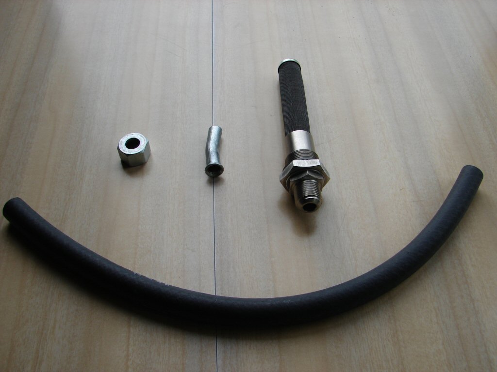
T160 oil union nut and top pipe, oil tank filter and 3/8"ID oil line which happens to be 14" in length. This line is a neat fit over the 5/16"ID pipes without being overly tight, so some sealant may be prudent when it comes to final fitting. I will see..
These are all the bits you will need after your oil feed pipe has been enlarged to 5/16"ID.
Whilst we are digressing I shall include this next pic.
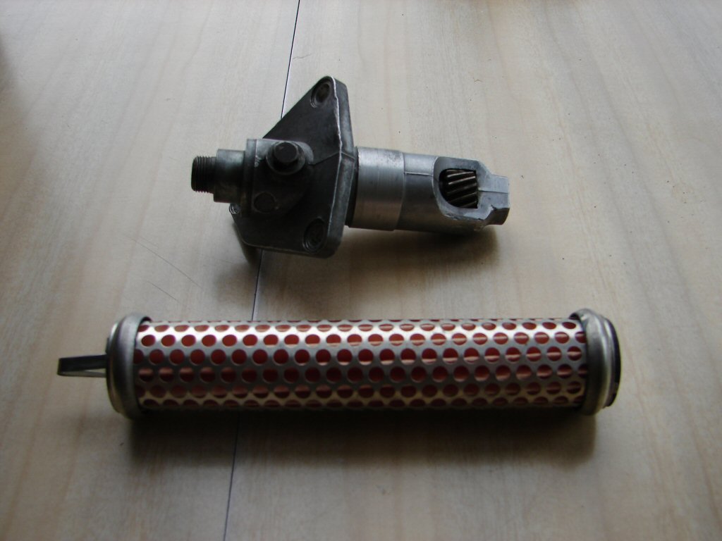
The tacho drive in this bike was totally destroyed when the errant conrod smacked the housing to bits and popped the cable connection and shaft out the front of the engine. A suitable used replacement had been acquired but was in a far off shed, so I visited that place and secured the said device, which I am pleased to report looked to be a very nice example.
Also in the pic is a "genuine" oil filter. If you happen to have an Emgo filter you will notice very apparent differences - this item has large holes all around its circumference, and looks much as I remember replacement filters looked in the late 70's. I can only trust it will behave as such.
Both these items and those in the previous pic will be installed next. Not because they are critical to progress - more because I view the fitting of the pistons and barrels as being an occasion where one can simply not afford to be interrupted - and in this run up to Xmas I can hardly consider that to be possible.
Perhaps next week will allow such..
The best examples of these parts that could be found in late 2016..
Picking up the thread - 2017.
The main problem with this festive time of year - apart from parts and services being unavailable - is that there are frequent interruptions to the normal state of things, and there are some parts of engine assembly that do not respond well to being halted midstream.
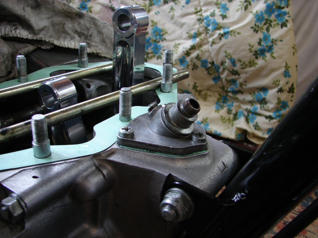
Hence my first efforts this year were all small but necessary additions. The tacho drive went on nicely after making sure there was no interference between it and the barrels that would annoy me later. Always keen to seal up holes where stuff can drop in..
Every gap gone is progress.
I next installed the oil filter and spring, then poured a decent amount of oil into the lower crankcases. I am using Castrol GTX 20/50 for running in and the first few oil changes, after which a change to synthetic oil will happen. I also filled the gearbox oil - a synthetic was used here, and one I use mostly. At 75W/90 it is slightly thinner when cold, but is stated as a direct replacement for SAE90 hypoid type oil. Still smells the same.
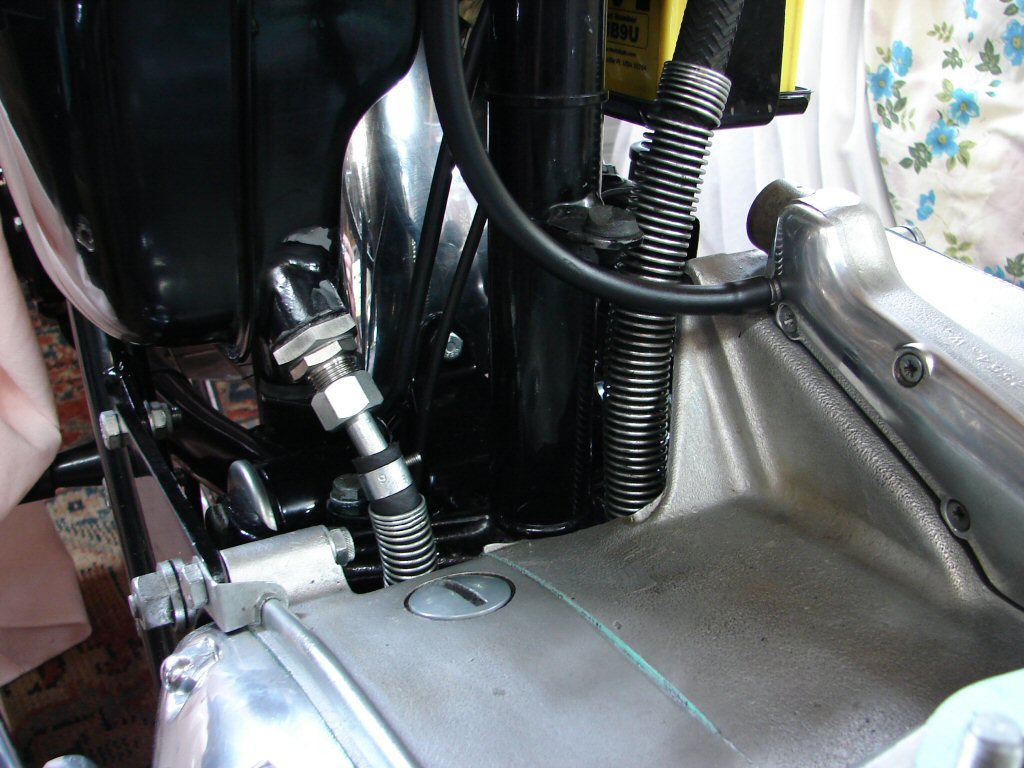
Final manoeuvre in this sortie was to fit the new T160 oil tank filter and top pipe, plus the new line down to the new larger intake pipe. The 3/8" line provided was a nice fit to the 5/16" pipes, but I chose to use a smear of silicon sealant at the lower end as well, as many oil seeps take place there. The return line got the same treatment after numerous flushings with solvent and dragging through of cotton rag until I was sure there were no remaining traces of contaminant that had begun to enter the system in the dying seconds of the engine.
The intention here is to complete the oil circulatory path so that oil can be pumped around the engine by hand before the primary is closed up. Some oil will be bled off at the return line to further ensure anything hideous is flushed away.
The Alaska pipeline and friend..
Next thing - pistons fitted to conrods. With the merest of warming, the pins were a compliant fit in the pistons, so fitting went very smoothly. Adequate clearance in the rods.
Three of a kind.
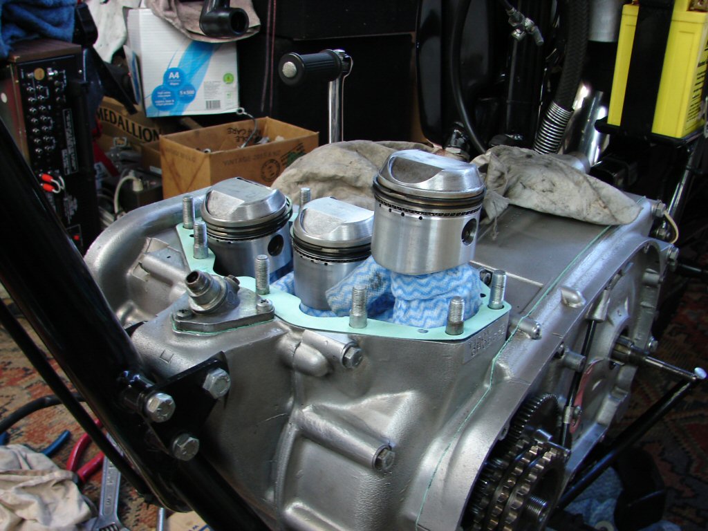
Remaining circlips slotted into place neatly, so now we fit the barrels.
Momentary pause while I grow another pair of hands..
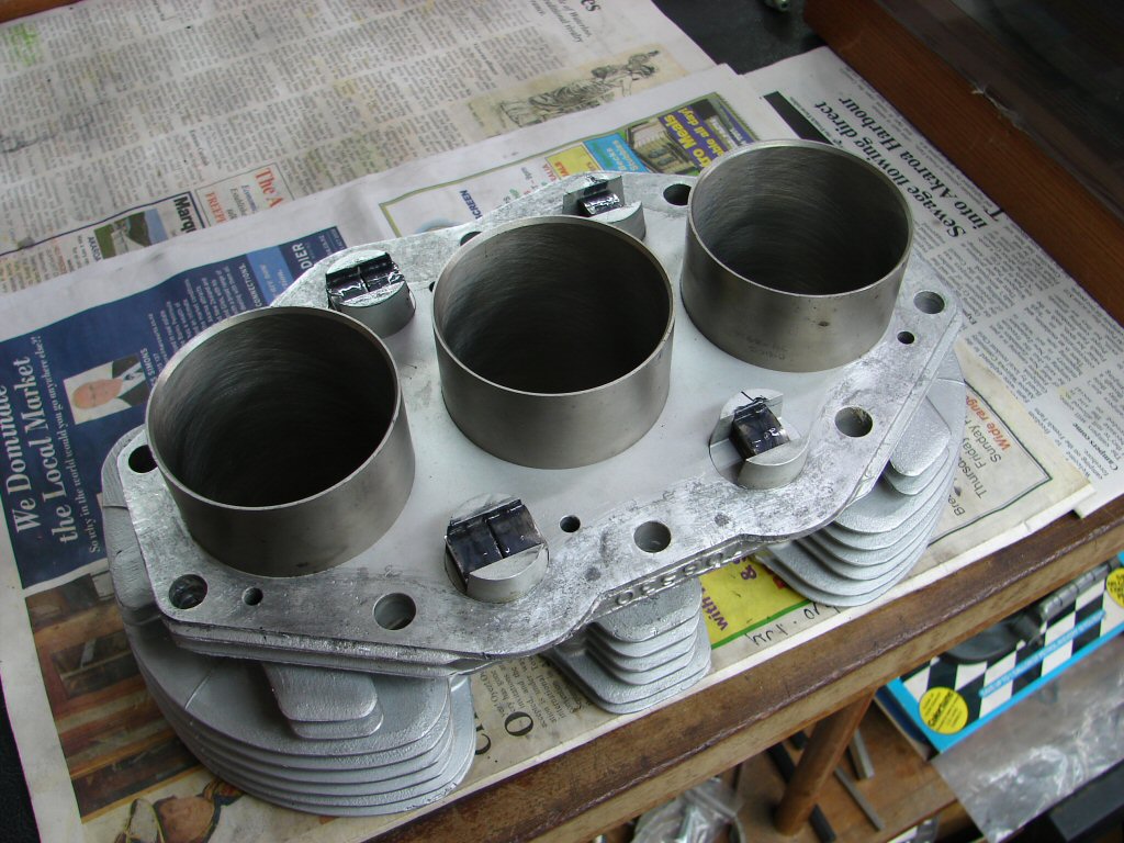
Barrels ready to go. Cam followers fitted, lubed, and retained by o rings so they refrain from falling down the hole.
Yup. They ready. So...
So - I invented another pair of hands. Pretty simple affair - couple of pieces of sturdy wire that stay put unless told otherwise. As each piston goes into its respective bore, the wires get adjusted slightly to lower the barrels.
Whilst crude - it does enable one to take things slowly and thus risk less haste induced problems. I have not yet found another human who can perform this task with such lack of complaint..
Ready for a swinging good time.
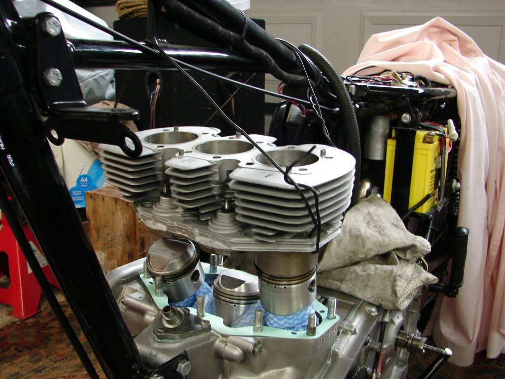
Finally - an afternoon with no commitments - time to do the business. Much to-ing and fro-ing but steady progress in a manageable fashion. 3 piece oil rings reluctant to enter the bore despite being within the taper. Steeling myself for the second lot.
Half time.
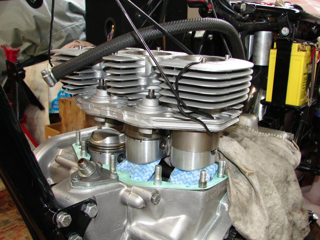
It gets more interesting on the third piston as the gap between the pistons and the crankcase diminishes, and care must be taken not to expose the rings on the first pistons. Despite that, the third piston co-operated very well until the oil ring, where it simply did not wish to enter the bore even though it had disappeared into the taper.
Concerned that the lower scraper may have been dislocated I raised and lowered the barrels several times, then it finally decided to play ball. Winding the crankshaft back and forth half a revolution a few times indicated that everything was happy going up and down, so I fitted the base nuts with a tiny smear of oil on each thread.
I shall leave it overnight then tighten again.
Done deal.
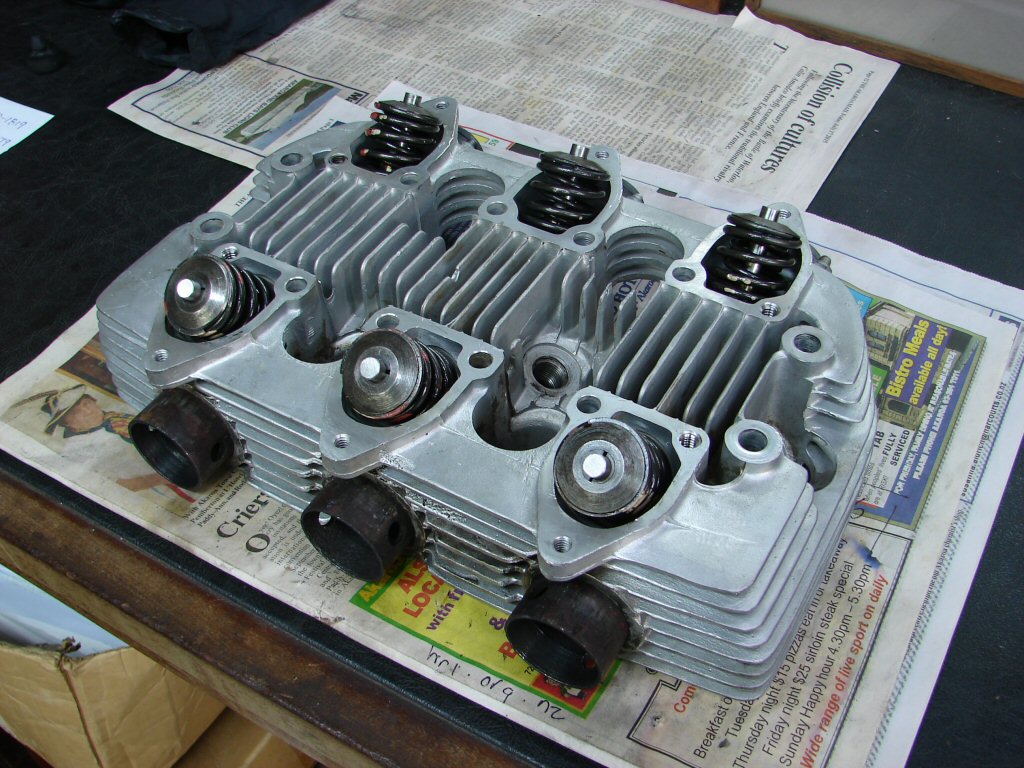
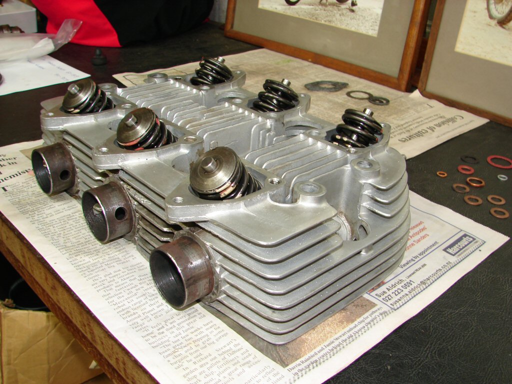
Final manoeuvre was to dismantle the valves from the cylinder head prior to cleaning it up. I can see that the valves in the centre most likely wore the impact of a piston at least once, so will need to check they are not bent. Cannot detect anything by eye. Nor can I detect any distortion of the head surface using a steel rule. With luck the only remedial work will be to remove a slight ridge around the centre combustion chamber where the piston crown made contact.
Began cleaning the head, but soon found it would need something more serious than the cleaning agents I have on hand. Although I was going to lap the valves in by hand, I am aware that either or both valves in the centre could be bent, so decided to DELEGATE.!
My usual chap is a long way out of town, so I phoned him and he recommended one of his clients who is also an engine reconditioner - so the head got delivered there today. Glen was immediately aware of what this head belonged to, and agreed to undertake the work I requested - namely refacing valves and seats whilst removing the bare minimum of material as I can see they don't need much - and giving attention to the centre valves if they show any signs of damage.
His cleaning bath should deliver a suitable finish without causing any stress to the existing valve guides which are fine for continued service. I was particularly impressed that the fitted guides were of the original type, with no seals but a pronounced taper for removing oil. These are quite rare of recent times, but to my mind are the best type as they allow good oiling of valve stem to guide and thus allow long service without excessive wear. There was no sign of any excess carbon buildup which would have indicated that too much oil was being drawn down the guides.
I shall now need to turn my attention to other areas of the bike while the head is absent.
And where better than here...
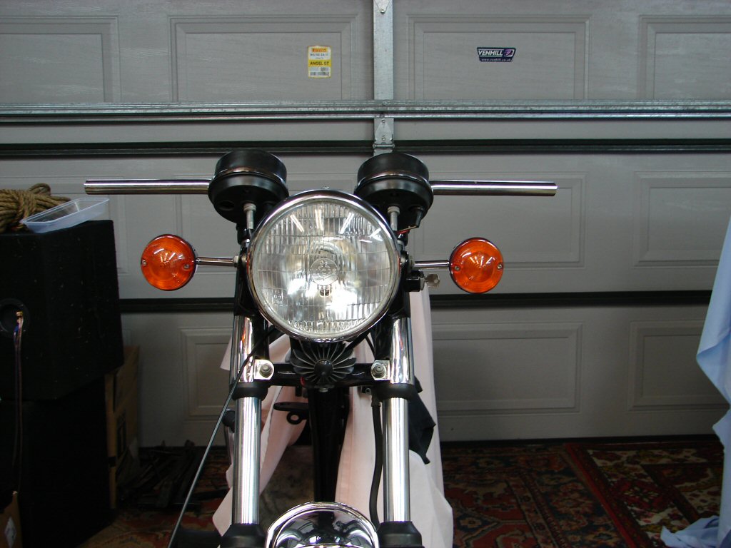
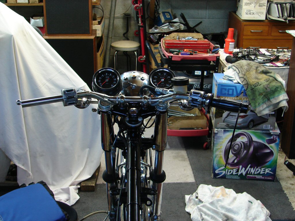
Original US bars.
These are being replaced by a set that originated on a 1970 Bonneville. The knurled bits for the clamps are slightly wide for the Trident setup, but the overall position looks just right from my perspective.
Flat - as in 'flat out'..
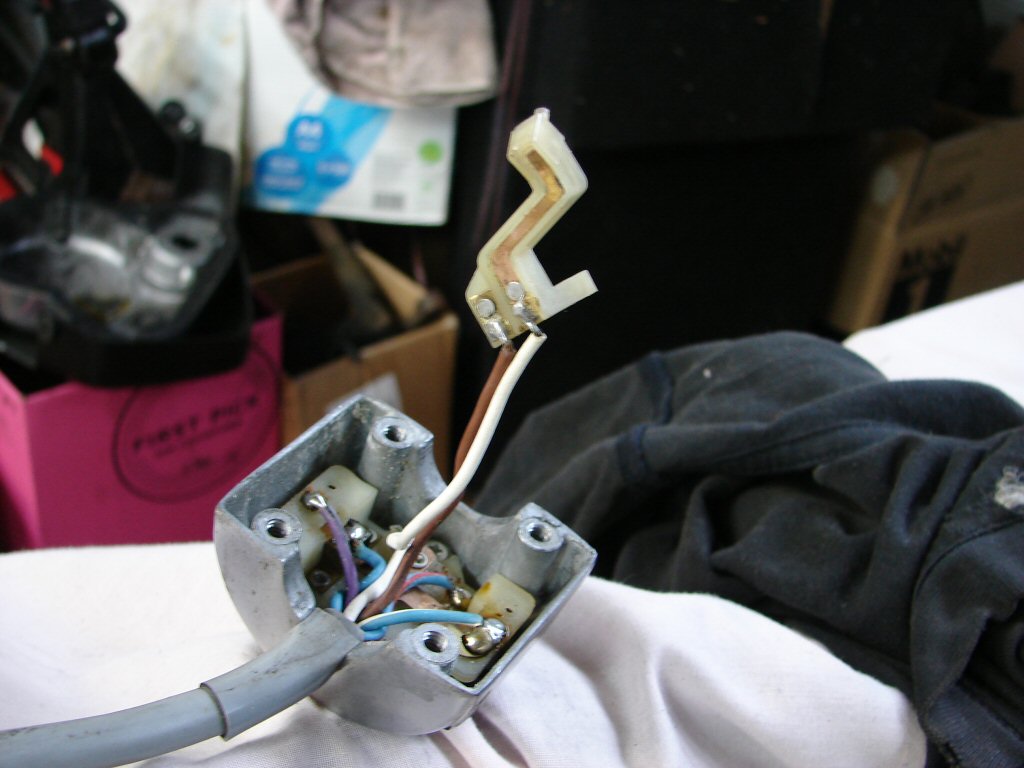
But of course - it is never that easy. I had been aware that there was no front brake operation of the brake light. The bike had been given wof's simply because it was assumed no switch was fitted, but of course it was. And not a happy unit.
The switch had obviously been hot at some stage, and the copper blade had melted the top of the nylon button that operates it. I trimmed that flat again. Once that was happy the switch still did not work. The contacts were not making even with the button now behaving. Some judicious bending of the copper blade to give more closing pressure on the haphazard contact arrangement resulted in a switch that now worked repeatedly. I shall try it again tomorrow to test it's resolve..
A Lucas masterpiece.
As is usual, the black paint on the brake lever housing had been damaged by brake fluid. I simply have to repaint them as they let the whole show down. I use an engine enamel which is very user friendly and happily rather durable. This process requires the entire master cylinder assembly to be removed from the housing, and as the fluid reservoir looked to contain some rather dark coloured contents, that could also be removed and cleaned at the same time.
Removing the actual lever revealed that the internal dust cover was in fact full of rusty coloured fluid. Whoopee. The cylinder had obviously been leaking for quite some time. If you recall - this bike sat in a lounge for 14 years after being restored, but of course, received no maintenance - as it was not being used. Does not stop jolly old rust though.!
Total strip of the master cylinder ensued, and here is the cleaned up assorment of bits.
No more crud.
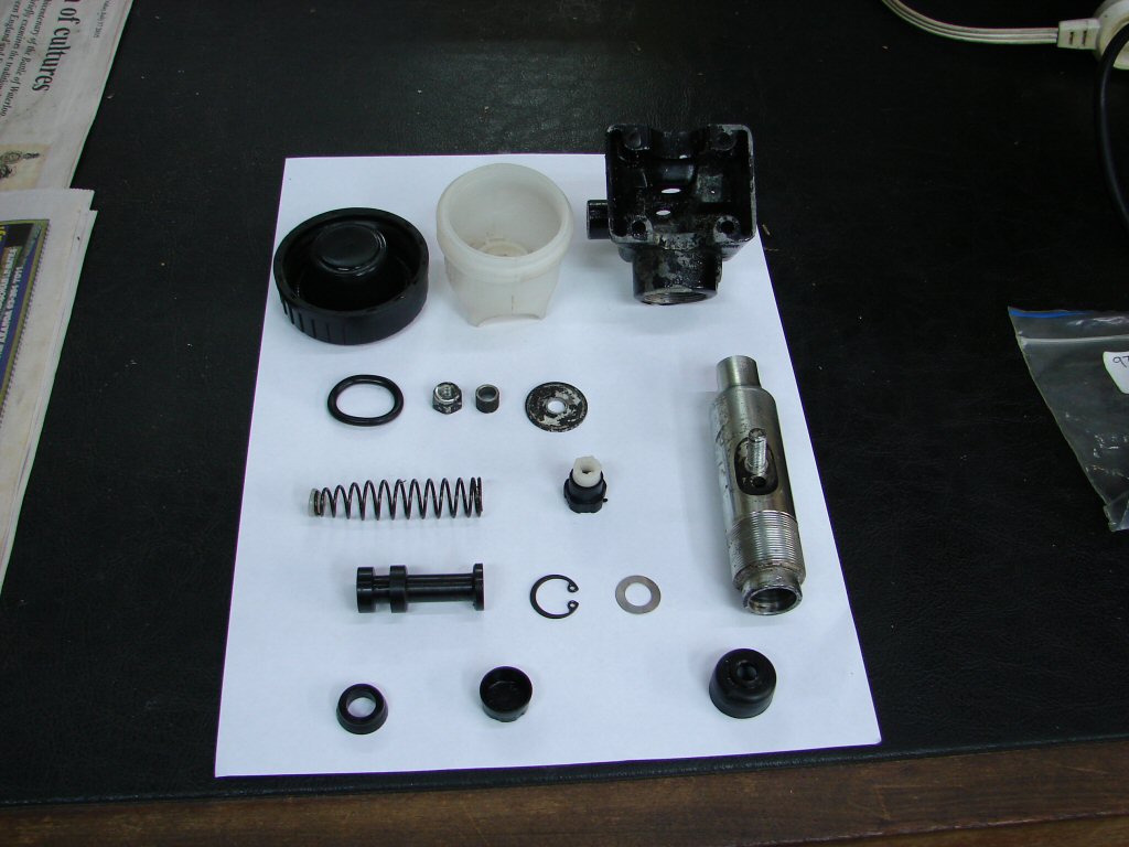
The seals will need replacing. I was able to address the cylinder bore with some fine emery paper, so hopefully just a seal kit will suffice. more parts to order. Meantime I am now doing battle with the left handgrip which has been attached to the bars with some space-age adhesive.
Another observation.
Of all the parts which are often assembled incorrectly on Tridents, the handlebar fixings have to be top of the list. These had some large washers inserted at the lower end of the clamps in an attempt to stiffen the bars up. No doubt the original arrangement had come under fire for being inadequate.
Well - hardly surprising. The cone shaped washers were all upside down, which results in play at the bars because the steel inners are supposed to fit into recesses on the flat side of said washers. To compound the error, the steel inserts for the top rubbers were totally missing, so the whole plot was understandably squishy.
No doubt the 'Factory' would have been roundly cursed for adopting such a pathetic arrangement - when in fact this example did not stand a chance of performing at all well due to the total absence of any sympathetic grasp of how it was designed to function.
Brake overhaul kit arrived from the UK. Good old L P Williams. I immediately assembled the master cylinder with new seals and various other bits that were included. There is a specific method for attaching the cylinder to the mating alloy housing - and I found that it ended up being one full turn further in than as previously assembled. I know not if this will elicit any improved performance, but is simply a result of "how it should be done".
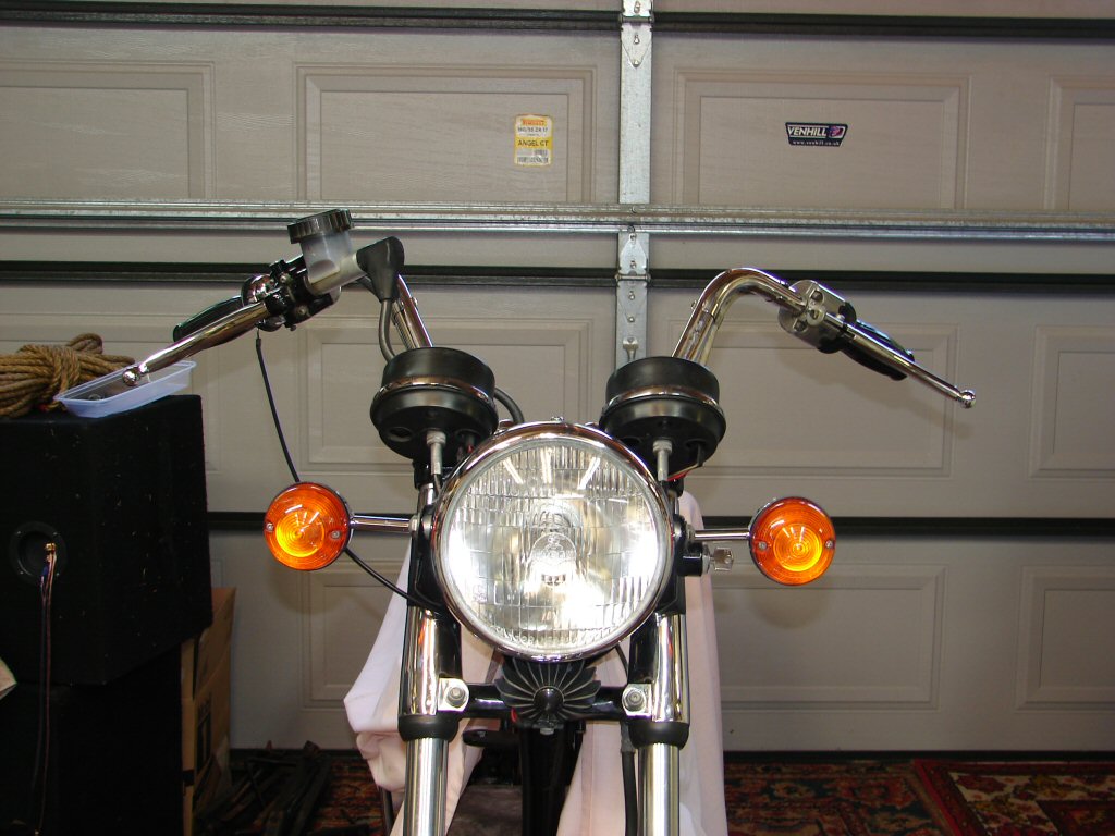
I had to roll the bars back a fraction to allow clearance between the new 'straight-in' hydraulic line to the master cylinder to clear the speedo. All that means is that the very outer bars slope slightly downwards, so not a bad thing at all. I began refitting the controls whilst allowing air to escape from the brake lines by cable tying the brake lever to the bars. It shall remain this way overnight.
I have also swung the clocks inwards slightly as their respective cables were jammed tight against the headlight mounting brackets, and obvious scars suggested that this had been a stress point since the bike was returned to service. It is strangely satisfying to make 'cycle parts' improvements whilst awaiting engine parts to be machined. I guess it maintains the flow to some extent.
Looking business-like...
As it happened, the cylinder head work was complete when I phoned today, so I rushed off in that direction and grabbed what was now a much more pristine looking piece of the puzzle. I am most impressed by the original looking valve guides, and wish I knew where they had been obtained.
Valves and seats refaced by minimum amount, and the slightest skim off the head to ensure no leaks at the gasket surface.
A miraculous transition.
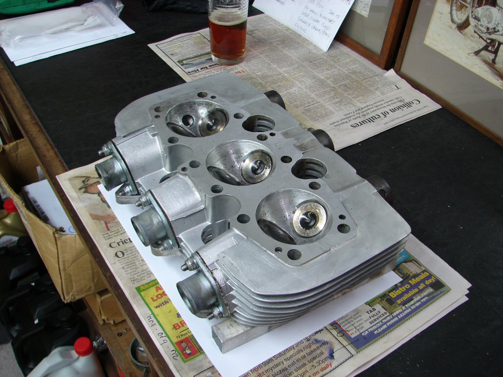
You will have noticed the special assembly "IPA" lube in the background. It does a wonderful job.
Top view of head with those excellent "no seals required" valve guides. I have the impression that fitting guides with stem seals limits oil to the point that valve stem wear increases to an unacceptable level. I would rather use guides exactly like these.
Perfect harmony here..
Naturally one is compelled to trial fit each new part in it's anticipated place, so I removed the valves and placed the head and new copper gasket on the barrels to see if anything was going to complain.
But wait.
What is this pray tell.?
This looks a bit special..
Moving right along.
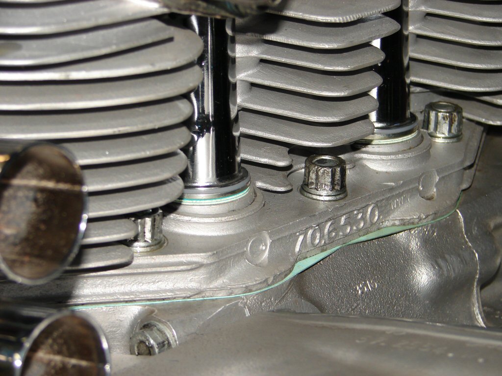
Pillar studs fitted to barrels. A canny hand when tightening these items will uncover any threads that are on the point of letting go. No such issues here.
Ready to head on..
Next step is to fit the valves and springs. Before doing so I checked the outer rockerbox mating surfaces for flatness. As per usual, the centre was slightly proud, so this was filed flat to give a uniform base for the rockerboxes to mount to.
There were alloy gaskets fitted for the rockerbox bases, and these will be cleaned up and used again.
The new copper head gasket will be annealed and coated with copper gasket spray when fitting.
Ready for another tour of duty.
Ok gang - here comes a fiddly bit.
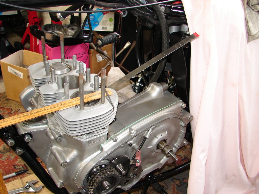
I need to check the cam timing, as not only do the camwheels have several sets of marks, but who knows what has taken place here in the past. I have recently seen the advantages of using the maximum valve lift as being a much easier point of reference than using actual movement of valves, with the added benefit that it can be achieved before fitting the cylinder head. As I do not own a dial gauge, I needed to come up with a simple method of producing a reliable way of measuring tiny amounts of movement of piston crown and cam follower.
So using part Kiwi ingenuity and part animal cunning, I came up with this.
A wooden ruler is placed across the piston and secured by a rubber band. As you might appreciate, a tiny movement of the piston results in a major deflection of the far end of the ruler, such that locating top dead centre was quite obvious.
Hi tech stuff...
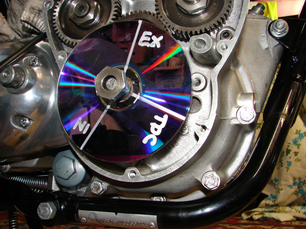
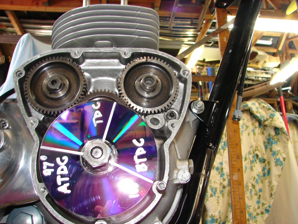
As I neither possess a degree wheel, I fished a dead dvd from the bin and drew some lines on it with a marker pen. Using my ancient flight planning protractor I arranged two lines which were measured relative to the TDC. These represent maximum cam follower lift for inlet and exhaust. I obtained the figures by using the valve opening and closing figures given in the factory workshop manual, then finding exactly half way between. They actually equate to 97 degrees after TDC and 100 degrees before TDC respectively.
After that I found a position on the edge of the timing cover joint face which gave an easy place to read from and hand tightened the dvd accordingly.
Wait til Microsoft hear about this..
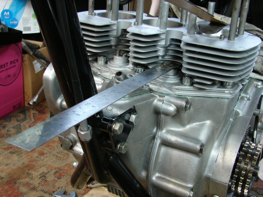
The final part of the equation is to accurately predict when the cam follower is in the middle of the period during which maximum lift is maintained - as the pretty much flat cam follower slides across the top of the camshaft lobe.
This time a steel rule is used which thanks to its own weight will hopefully ensure that the follower retains contact with the cam at all times - mostly when going down hill.
Metric or Imperial Sir.?
A quick trial of a general nature showed that I had reversed the inlet and exhaust marks on the disk. I drew up another, then found I had done exactly the same again. What?
Ah - good old human minds - double-thinking everything. I was drawing the marks as if they were static - that is - in the positions they would appear relative to the crankcase. In reality, as the disk turns, before TDC should of course preceed the TDC mark - not appear where before TDC actually is on the engine. Sounds simple enough, but I still made the same mistake twice. At least the error was pretty self-evident, but it does show how easy it is to get baffled by all this bullshit.
The best thing was, my trial gave adequate reassurance that this was all going to work brilliantly, so I made a couple of small alterations.
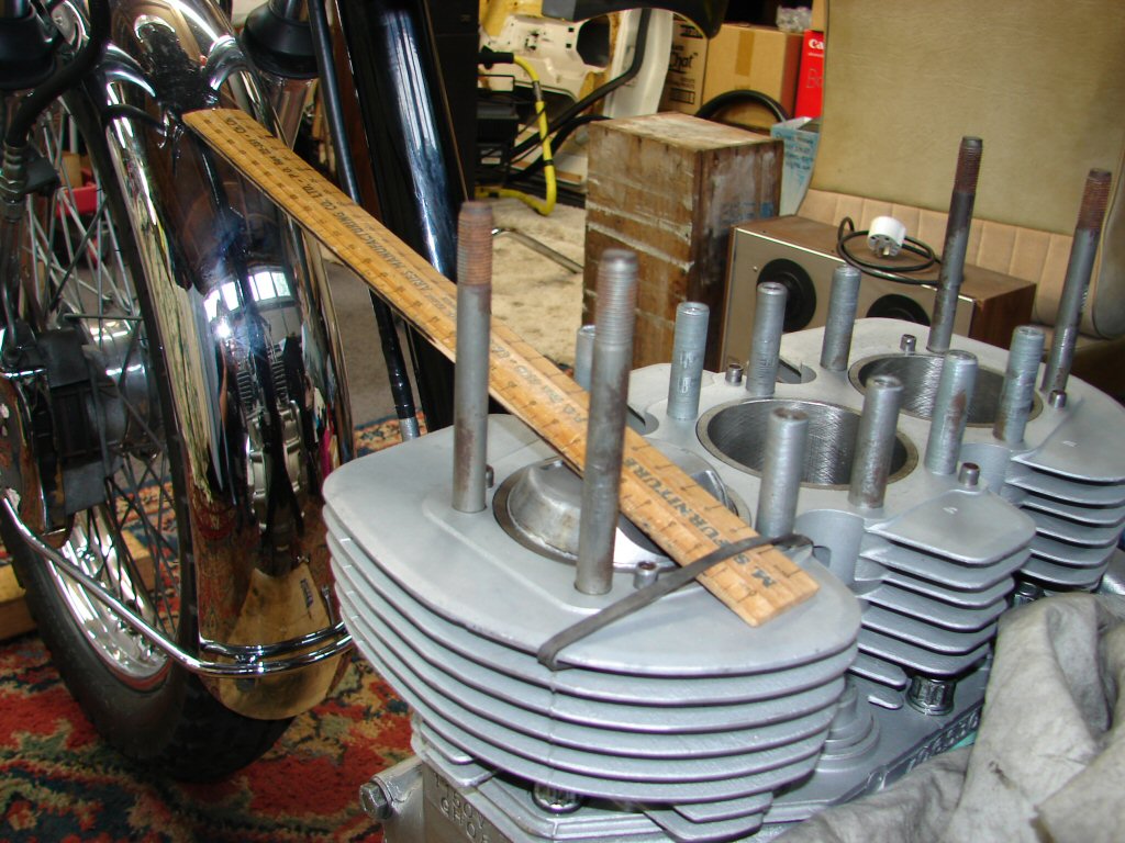
Rules of thumb.?
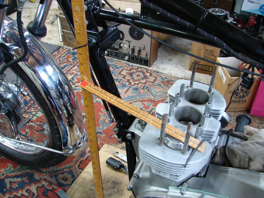
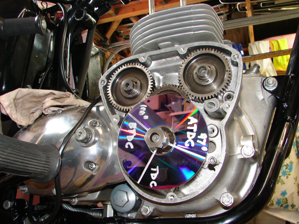
Firstly I attached a yardstick so that movement of my TDC ruler could be more accurately gauged. By turning the engine forward and backward using the front primary sprocket I was easily able to judge the midpoint of the piston's ascent.
I then positioned the MkII degree dvd so that TDC aligned with both my original marks plus those I had now inscribed on the head of an allen screw which sat next to the edge of the disk. The photo was taken from slightly lower so a small amount of parallax error is forgiven.
I repeated my positioning procedure several times from the primary side, and each time I returned to look at the disk it was absolutely spot-on the TDC mark.
Fantastic.!
I love it when a plan comes together.
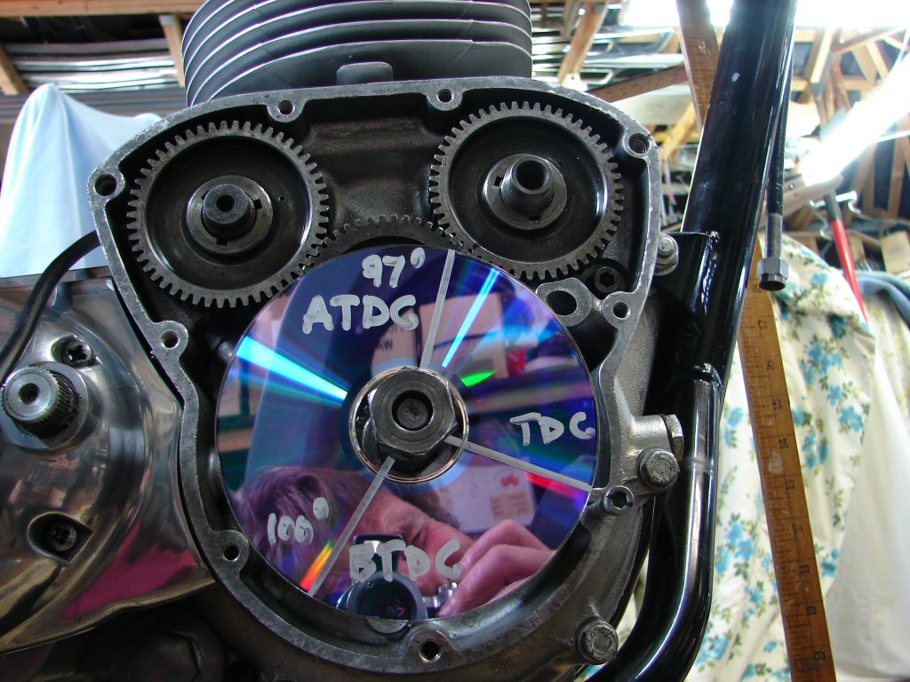
I had found a hand-scratched mark on the edge of the exhaust camwheel which seemed to coincide with my rough idea of where the timing mark should be, so I put a mark on it with a black marker pen, which is visible in the picture above just to the right of the 97 degree line on the degree disk.
Working from the primary side again, I wound the engine forward until the steel rule on the cam follower reached its highest point then began to fall again. By toing and froing I could confidently find the dead centre of maximum lift.
Back to the timing side to check my marks, and lo and behold, a perfect match once again.
I like the way this is shaping up.!
I thank the previous builder for this result.
In the above photo you can see how far the steel rule has risen above horizontal to attain max lift - a huge deflection which once again made finding the mid-point very easy indeed, but more importantly - repeatedly so.
Reassured that someone's hand etched mark was reliable, I looked carefully around the edge of the inlet camwheel and found a similar mark. I did a test run with that but found max lift arrived about 1/4" past the 97 degree line looking at the outer edge of the disk. I advanced the camwheel by 1 tooth and tried again. This time max lift occurred about 3/8" before the 97 degree line.
I returned it all to TDC and removed the inlet camwheel. Placing the wheel so as to position the previous (anticlockwise) keyway in line with the key on the camshaft, it appeared that this would retard the cam by about 2/3 of a tooth. As the cam was currently too advanced, this seemed to be the right move, so I fitted the camwheel then repeated the procedure.
Once again, the amount of deflection of the steel rule was so great that it was a cinch to locate the mid-point.
Going up..
Lets check the magic wheel then..
Bingo.!
Too cool to not laugh..
The inclination of the steel rule is quite evident just behind the barrels in that photo.
With much humour - laughing out loud - I was able to repeat my locating of max lift from the primary side, then return to the disk and find it exactly as pictured.
What a hoot.!
Worth noting that the thickness of the lines on the degree disk are equal to 2 degrees of crankshaft movement. That is equal to 1 degree of camshaft movement. With the naked eye it is very easy to see if the alignment of the marks is dead centre or slightly offset, and every reading was in fact spot-on when viewed from a horizontal side position.
I am prepared to bank on these results.
I am also immensely pleased to have achieved what I feel are very accurate results whilst using very basic tools.
Used in a thoughtful way.. hahaha.
The intermediate timing gear has both a dot and a dash where it aligns with the inlet camwheel. The dash is one tooth further advanced than the dot. I have no idea which of these marks the engine may have been previously timed to, but it seems that I used the same mark on the camwheel as had been located during the previous build, as none of that factory 'dots' on either camwheel seemed to make any sense at all.
I timed it to the dash, and yet it was still about 1/3 tooth retarded, but is now right on. I have no idea if that would be discernable from a rider's perspective, but I shall at least be happy in the knowledge that it is as good as I can possibly make it.
And that is the point really.
Not much to report today. Cleaned the exhaust stubs and filed a lead-in on the forward edge. I will use some silicone sealant as I fit the headers to the cylinder head, but a mere fraction of what was obviously used during the last assembly.
It seems there may also be some complications to this process as the parts in question will be non-standard.
Fine tuning..
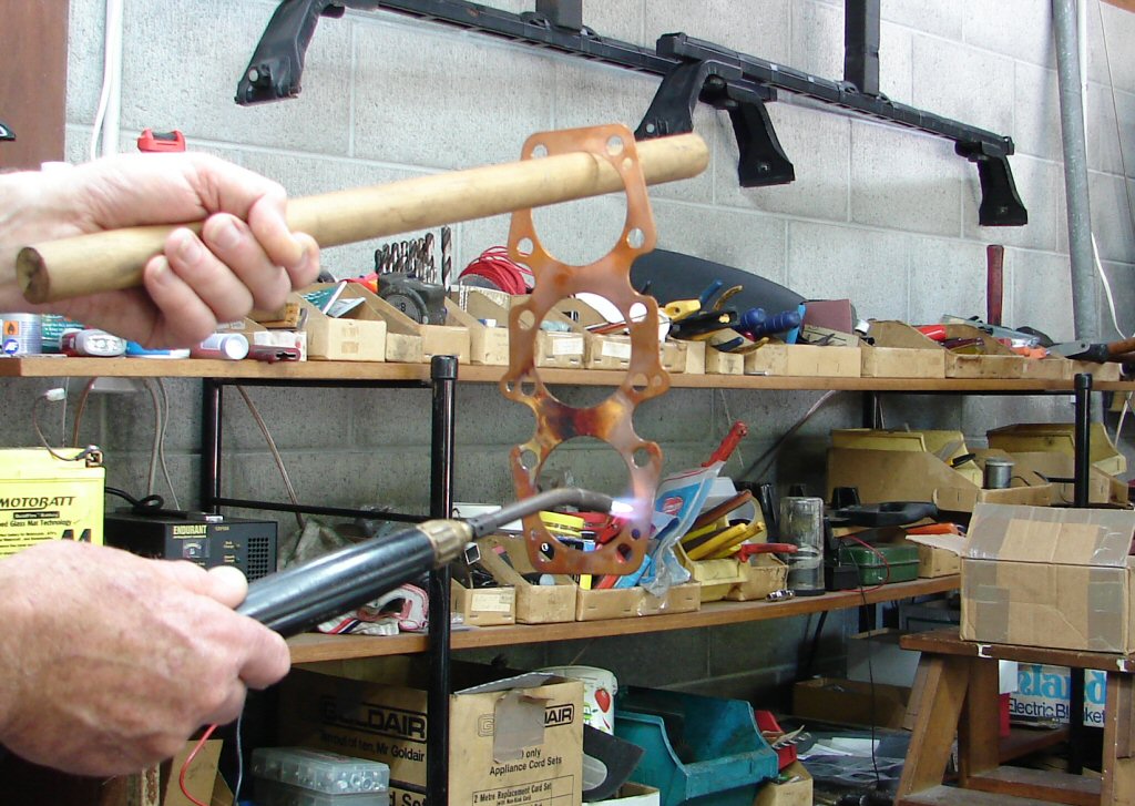
Despite this being a new copper head gasket, I am still annealing it. The softer it is the better it will adopt the surfaces it finds itself attached to in the near future.
Kind of interesting juggling acetylene torch and red hot gasket while telling the camera to go ahead...
Lovely colour of copper going soft..
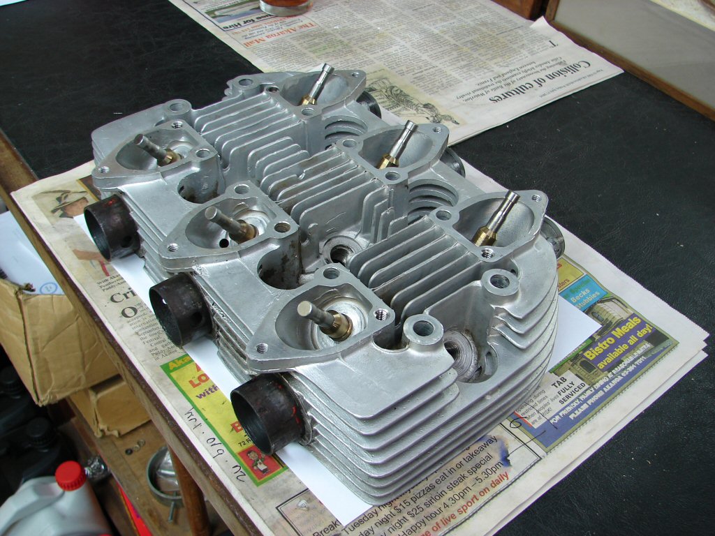
Now. Here we have a number of synchronous issues that were not arranged for your edification at all. They just chose to be in the same place at the same time. There are 3 things that I am sure will not have escaped your attention, but I shall introduce at least one more.
1. A learner (loser..) plate.
2. A photo of a Norton Commando Interstate that I rode to the IOM in 1981.
3. A headline that clearly states "Collision of cultures".
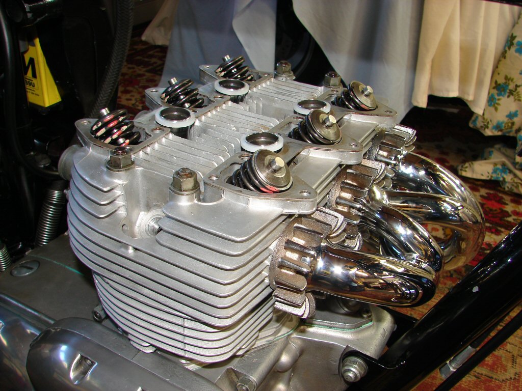
4. A Trident cylinder head with a rather unorthodox header arrangement attached to it.
I shall allow you to draw your own conclusions...
Innovation.
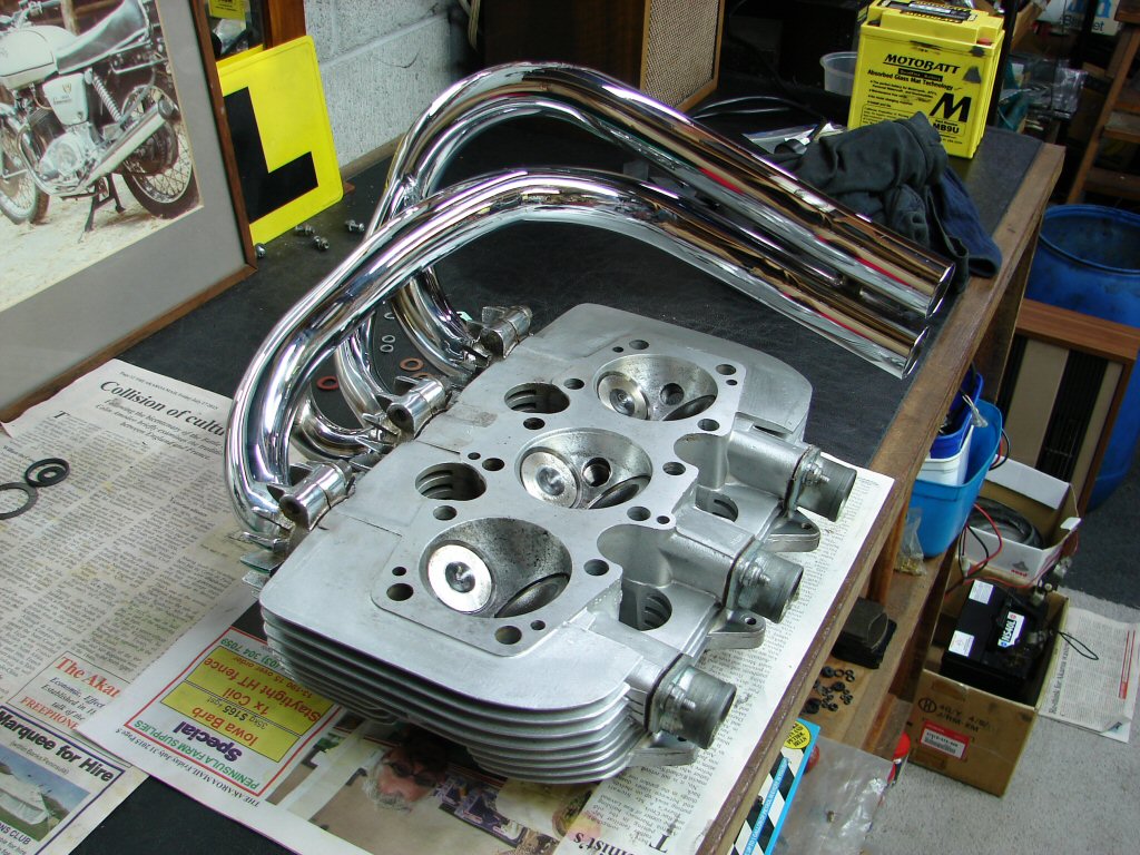
When you are doing new things you simply have to accept that the normal approaches may not apply.
This header system was very much touch-and-go during the trial fit as to whether it could even be fitted once the cylinder head was attached to the cylinders. As I am easily bored I decided that it was not a risk worth taking, henceforth I have attached the headers to the head prior to assembly.
There. That was easy wasn't it. I will however leave you to decide which situation the headlines may have been referring to. They did seem to wish to be relevant.
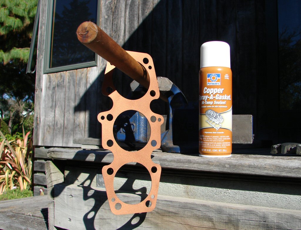
Prior to fitting the newly softened head gasket I coated it with a copper spray. This both acts as an adhesive plus prevents bits sticking together - sounds like an oxymoron to me, but if it assists a good seal at the gasket I am prepared to accept that getting it apart at a later date might not be such a fun thing. I am hoping not to have to test the theory..
Being thorough.
When the spray has suitably dried so the gasket can be handled easily, the gasket gets dumped unceremoniously on top of the barrels..
Touchdown.
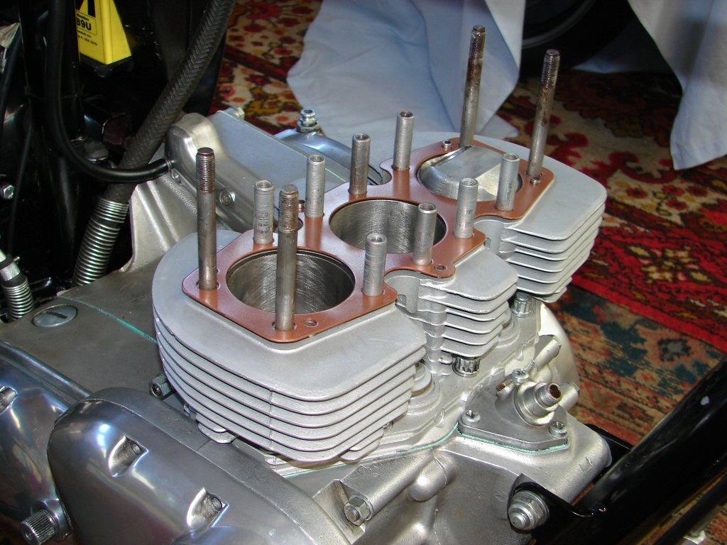
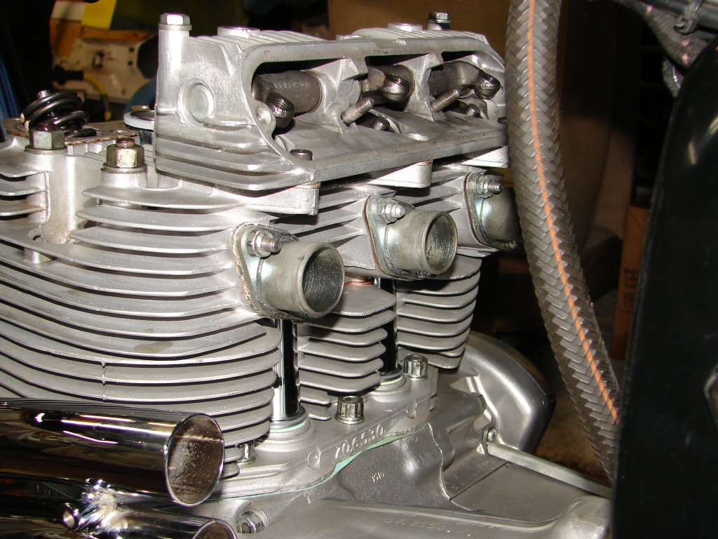
After which the cylinder head is dumped on top of it and tapped down over the oil drain dowels by judicious use of a rubber mallet. I forgot to install the exhaust pushrod tubes as the head went on, but luckily they were still able to be fitted. That must be a T160 thing..
Lightly oiled outer cylinder head nuts pinched down to keep a bit of pressure on the gasket, and top pushrod tube seals fitted in place. The cleaned up rockerbox base gaskets are also sitting in place. They are rather thick aluminium items, and the reason for their thickness became evident when I trial fitted the exhaust rockerbox without the gasket and found a clearance issue between the tops of the valve retainers and the bottom of the rocker arms. Adding the gasket solved the problem adequately, but reinforces the idea that any further head work would involve replacing the exhaust valves and possibly also the seats.
Trick looking headers..
Now we check the compression of the pushrod tube seals. There are no pushrods fitted, nor are there any valve adjusters, so nothing to get in the way while I gauge the amount of 'crush' that the seals will be subjected to. Too little or too much would encourage oil leaks.
Squeeze me baby..
Because the rockerbox gaskets are so thick, I took a punt and fitted two fibre washers under each pushrod tube rather than the usual one. The seals that were supplied with the gasket set have a slightly translucent appearance and seem firmer in density than the white ones which used to be supplied. It seems I achieved a desirable amount of squish as you can see that the exposed outer edge of the seal has a slight bulge suggesting a reasonable amount of pressure, without being forced too much out of shape.
Its a wrap.
Providing the exhaust pushrod tubes exhibit the same behaviour I will be all clear to complete the adding of pushrods and adjusters, and complete tightening the cylinder head and adjusting the valve clearances.
After that I will make a final visual check via a spark plug hole that valve operation is normal, and then I can assume the valve timing is complete. I discovered today that the bronze bush inside the intermediate timing gear is badly worn, so shall need to order a replacement.
Time for Part III.