December 2015
The reincarnation of "Trevor" Part I.
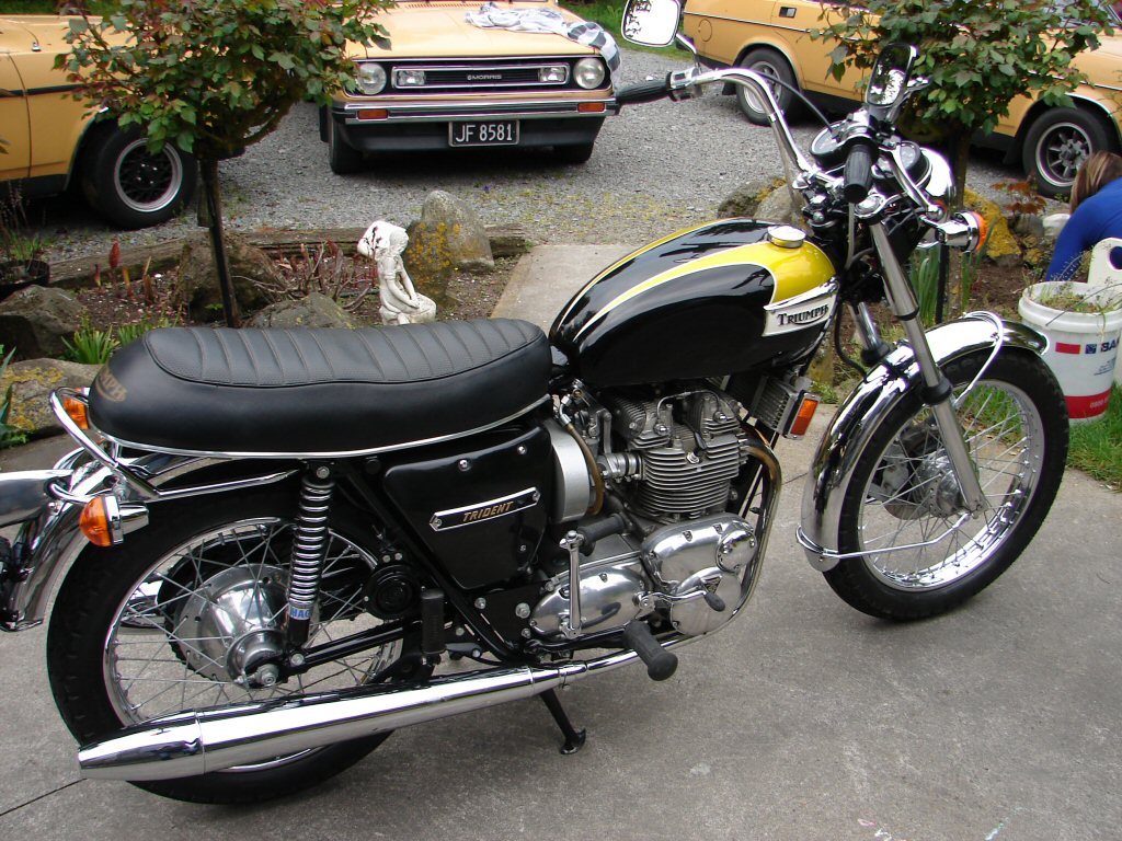
"Trevor" was the name bestowed by the current owner on a rather tasty T150 Trident which was purchased "as-is" after a major meltdown. Although it had been the recipient of a megabuck restoration in the late 90's, and had then sat unused as a focal point in someone's lounge for 14 years, this bike proved to have had some dubious engineering practices applied in the process. I was involved in making routine adjustments during the running-in process.
Trevor in "restored" form circa 2013.
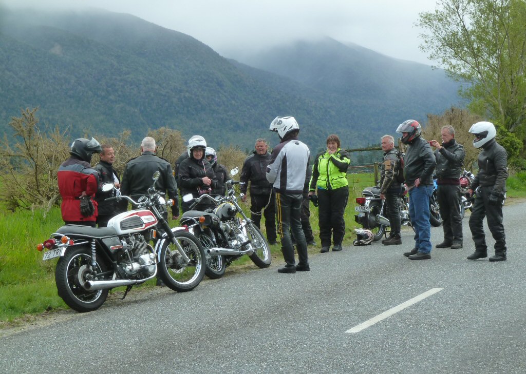
Trevor seized up in a dramatic fashion on the 2015 Triples Run between Jacksons and Moana. It was towed to Moana and left at the service station there to be collected the following week. The owner at that time chose to sell it on rather than repair it, and the current owner bought it.
Breakdown. Towrope being prepared centre..
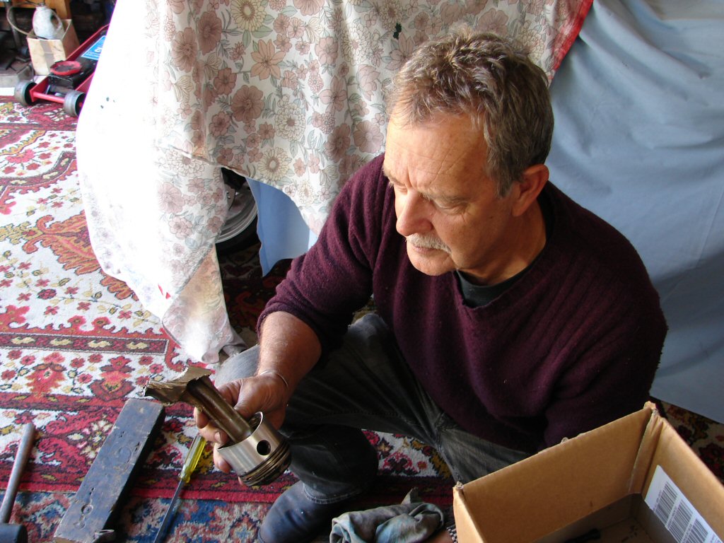
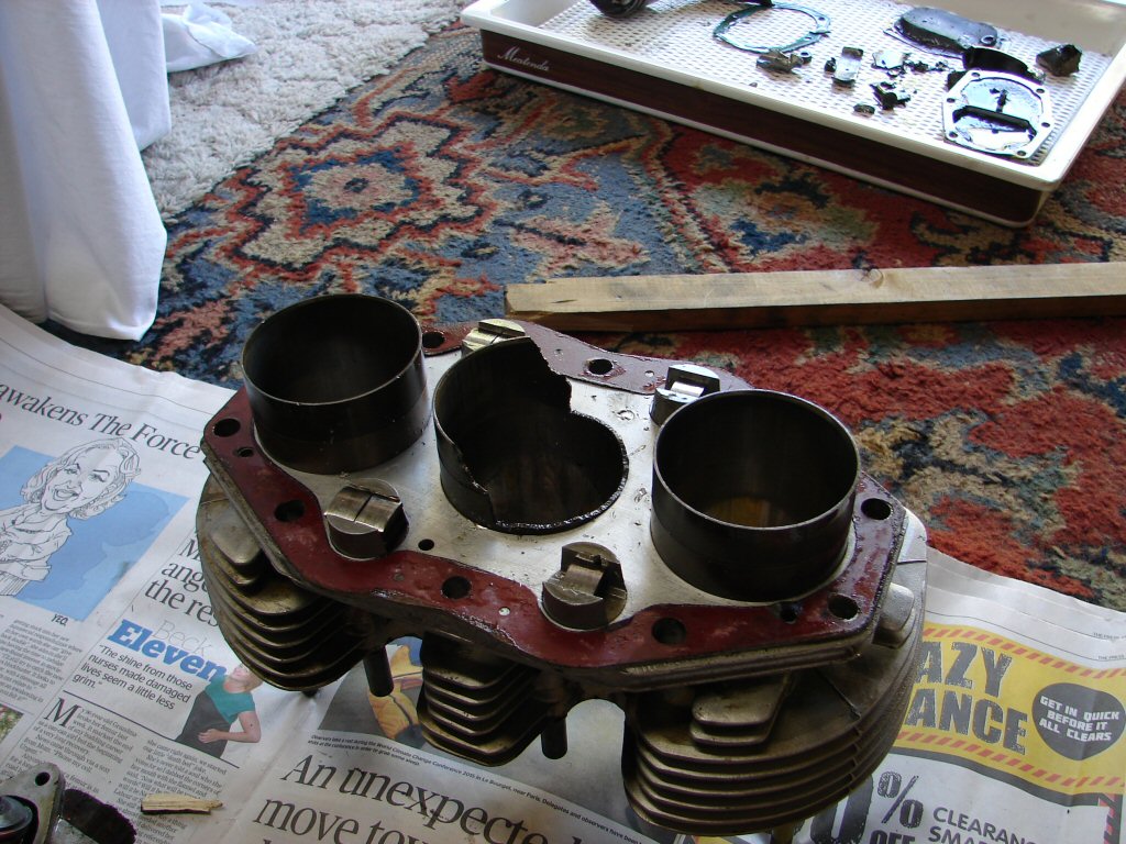
The bike was delivered to my garage a month later, and the new owner and I stripped it down. We were hoping to find a broken piston, and having spied two pistons at the top of their stroke through the spark plug holes, we were still leaning in that direction. What we found was something much less desirable.
This probably explains it..
The centre conrod had broken the big end location completely off, and had damaged the exhaust camshaft and tacho drive in the process. The centre cylinder liner was smashed and every journal on the crankshaft was seriously damaged. The motor had obviously been suffering from low oil pressure for some time.
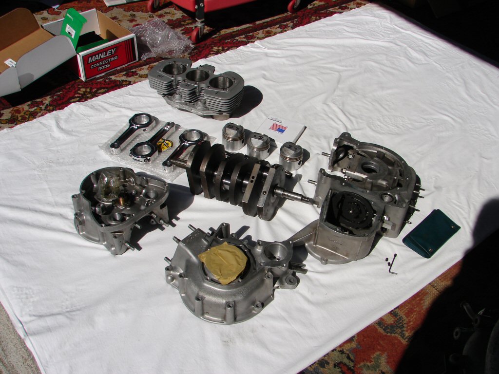
On the plus side, the crankcases were intact, and the pistons were in perfect condition. Total mileage since restoration was around 4000 miles.
The sump plate was removed allowing all the debris to be released, and the full extent of the carnage to be appreciated.
Answer was revealed dead centre..
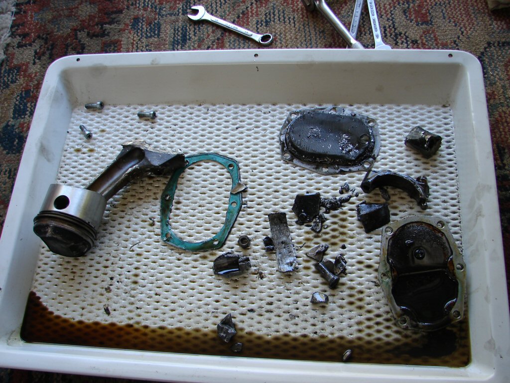
It transpired that whoever assembled the motor had used the original conrod locknuts, one of which had fractured, losing its locking threads and allowing the nut to come loose. This had increased clearance at the big end bearing causing major loss of oil pressure to all crankshaft bearings, and finally resulted in a seizure which broke the centre conrod, most fortunately at low speed, so the damage was contained within the crankcases.
Barrels took a direct hit..
In a timely happenstance, a set of standard barrels appeared on Trademe, and they were purchased and bored to suit the original pistons. There was found to be a business in Rotorua who were able to build up crankshaft journals and regrind them to standard. They specialised in large engines, but after some months they retooled and treated the Trident crankshaft. An expensive process, but the ultimately most desirable result.
Some NOS bearing shells were obtained, new outer main bearings fitted, crankshaft oil gallery plugs drilled out and replacements provided. A new set of "Lightning" conrods came from Norman Hyde, and the entire crankshaft/piston/conrod assembly balanced.
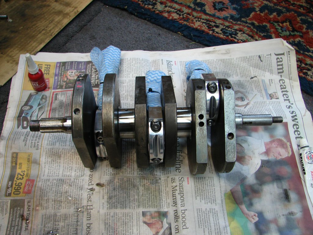
Parts coming together..
After laborious cleaning of the oil galleries the new plugs were fitted and the rods assembled on the crankshaft. These rods have their big-end bolts tightened in two stages. After the first stage it appeared that they were a bit on the tight side. They would rotate, but not fall under their own weight, which would be expected.
Present arms..
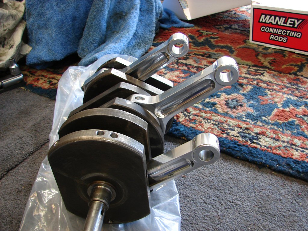
After fully tightening the first one it was obvious that there was a dimension problem somewhere. It was all stripped again and everything measured. Whilst the main bearing journals were the correct size, the big-end journals were .001" larger than the max allowable size. The desirable clearance would have been .001" smaller than the conrod bearings, so the offending journals were ground to give exactly that clearance to their respective conrods.
Cleaning deja vu..
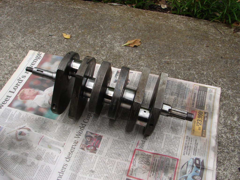
Visible on the right side big-end journal is a nice radius to the oil feed - this was done after the regrind as the rebuilders had left a fairly rough edged hole which had made its presence felt on one big-end shell. One can never rely on anything being done as expected - check and check again seems to be the rule.
Galleries cleaned and plugs refitted with a small amount of loctite to dissuade them from ever migrating in use. This time the assembly went as expected and all 3 conrods would now fall under their own weight.
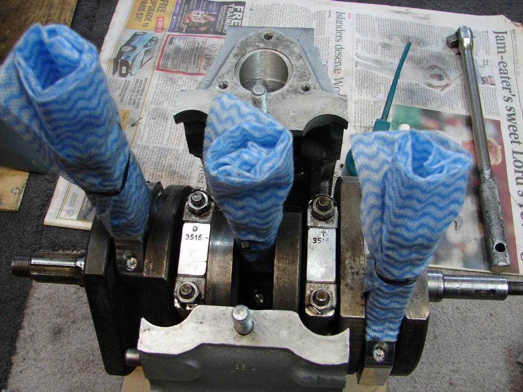
The master copy..
The crankshaft assembly was now fitted to the centre crankcase and the main bearing caps torqued to 18ft/lbs and the locking tabs engaged. This always feels like a major point in the rebuild - as it confirms that all the machining has been completed. This is the core of the motor and its most vital assembly.
Heart of a triple..
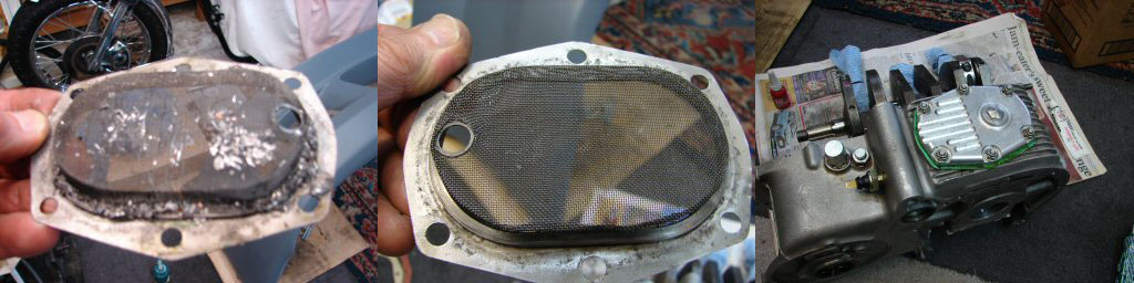
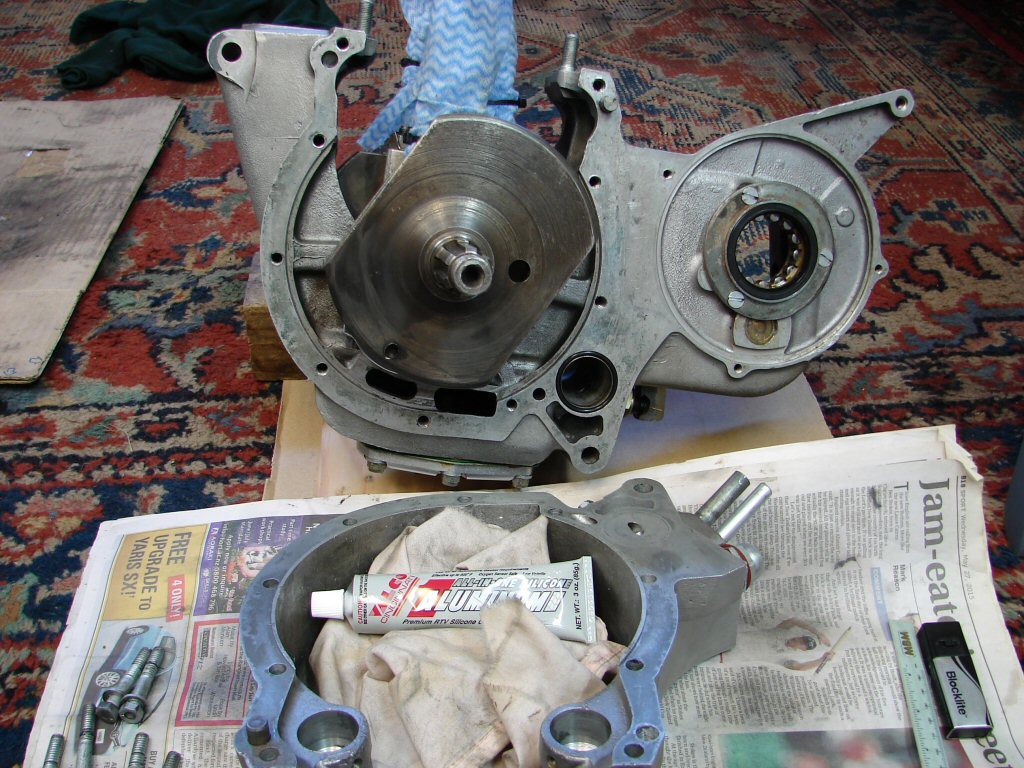
Prior to the crank assembly being fitted to the centre crankcase, the sump oil filter was cleaned and repaired, and the sump plate fitted. A mild smear of silicone sealant was applied to the gaskets as this is a leak-prone area. This assembly will be disturbed after a few hundred miles running to clean away any running-in debris, and as a part of the first oil change.
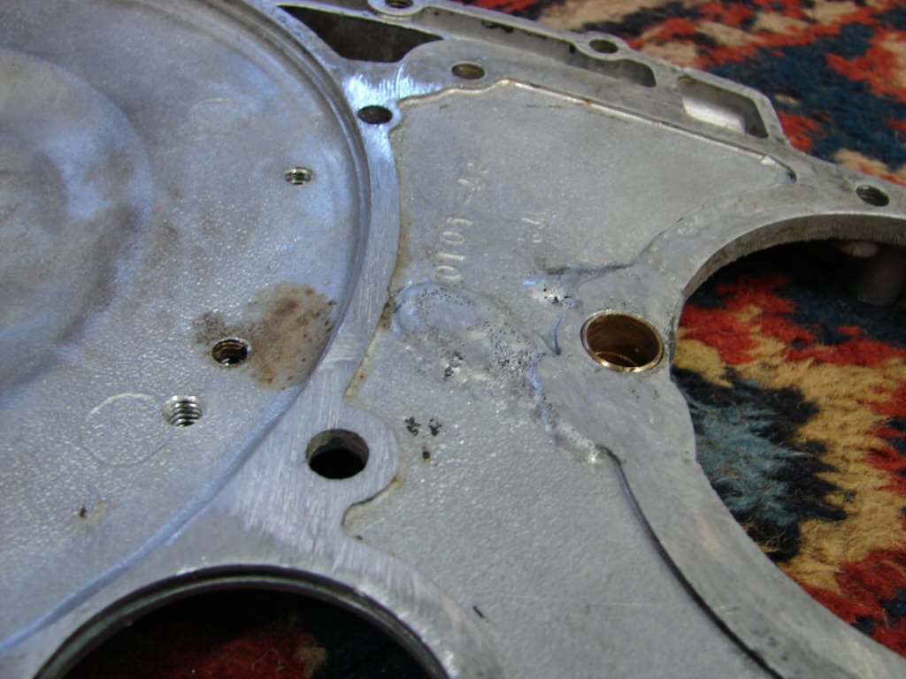
Bad/good/better..
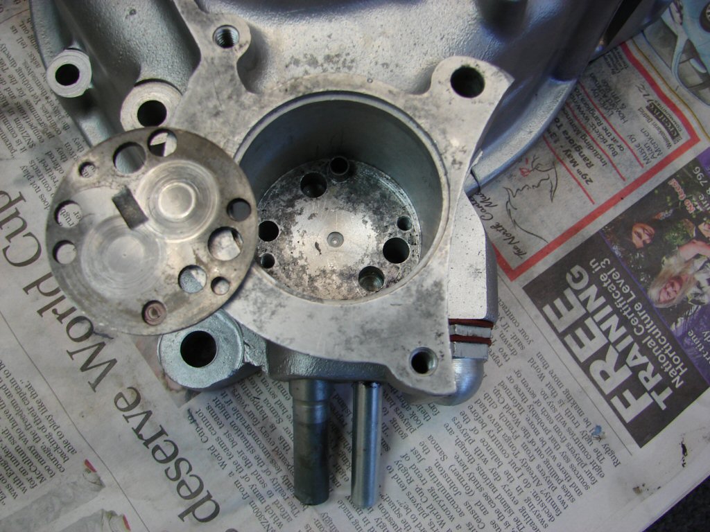
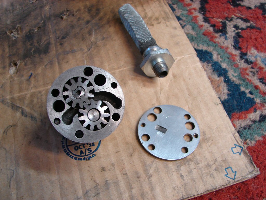
Since the stripdown, the drive side crankcase has been the recipient of a new oil feed pipe. The original was 1/4"ID, but the factory adopted a 5/16"ID pipe as being more advantageous, and included this as a standard feature during T160 production. The modification involves the fitting of a larger pipe and opening up the hole into the oil pump area by the same amount. In this photo I have placed the end plate from the oil pump in a similar attitude so you can see that there is one hole in the end plate that also needs opening up. I shall do this - and address the surface wear on the plate at the same time - before refitting the oil pump.
Alaska pipeline..
Next step is to fit the drive side crankcase. A new o ring has been fitted to the oil filter cavity area in preparation. For the first time I am using a new sealant for the crankcase sections. In the past I have used blue hermetite, but at the suggestion of a very talented machinist I am trying an aluminium coloured silicone product from the USA - and I rate American products highly. Hopefully Mr 'T' will encourage more.
Game of 3 halves..
When you read the instructions on your tube of silicone sealant, it advises using a 'bead' of this or that diameter - I do neither. Using a surgically gloved finger - because I am posh (or fearful..) these days, I smear a thin coat of sealant across every surface I wish it to be, avoiding oilways and dowel holes etc.
I then allow a certain time period for the sealant to 'skin' before bolting the surfaces together. The bolts are all in place and have had their threads and washers lightly oiled for a stress-free tightening. Main ball bearing has been adequately oiled.
The coming together.. brothers..
After tightening all the retaining bolts here, attention is turned to the other side. In preparation for the fitting of the timing side case, the camshafts have been fitted into adequately lubricated drive side bearing cavities. Assembly lube has been applied to all cam lobes. The exhaust cam is brand new as the original got severely whacked by the errant conrod.
The third half.
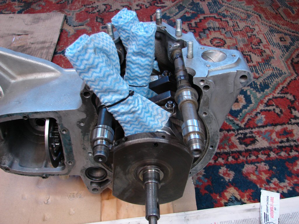
The inner part of the roller bearing tapped on without too much resistance thanks to being immersed in boiling water for a few minutes. I applied a smear of loctite on the surface beforehand, which also acted as a lubricant during the process. I cleaned everything off with WD40 immediately, so any water or displaced loctite would be flushed away, after which I dosed the bearing and camshaft journals with engine oil.
Closing time..
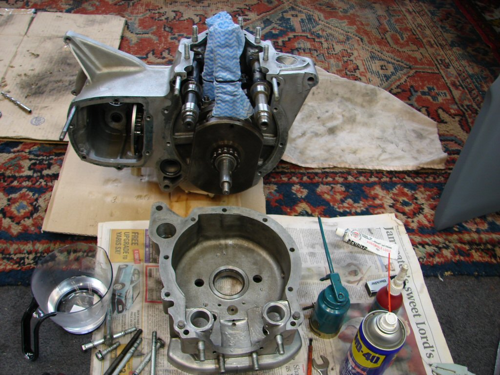
I tend to take my time with all of the assembly process. It is easy to do something in the wrong order and then have to reverse a bit, so plenty of observation and trial fitting is the best way to ensure you get it right first time. The timing side case behaved well during its transition, although I made sure it pulled up evenly so as to avoid stressing the cams at all. They survived the ordeal and both turn freely enough - as does the crank.
As this assembly is still easily manageable by myself, I will install this in the bike and continue reassembly there.
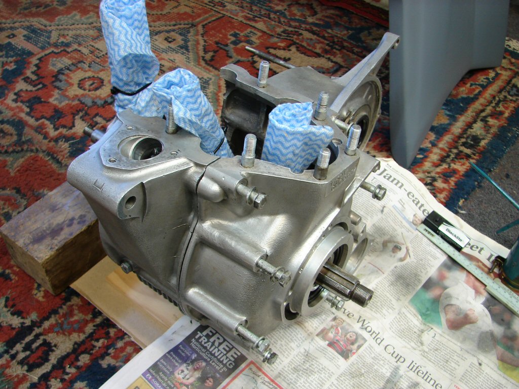
Critical point - bottom end complete.
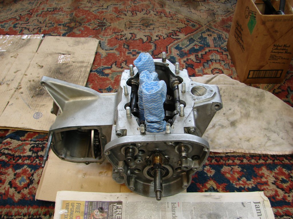
With the aid of a sturdy wooden box placed under the frame, I simply sat the engine where it should be, then began to fit a bolt or two to convince it to stay there. I am exceedingly grateful that the rest of this bike is pretty much sorted, so it is mostly just an engine rebuild. Having said that - there are a few 'other' items to attend to.
Looks much at home here.
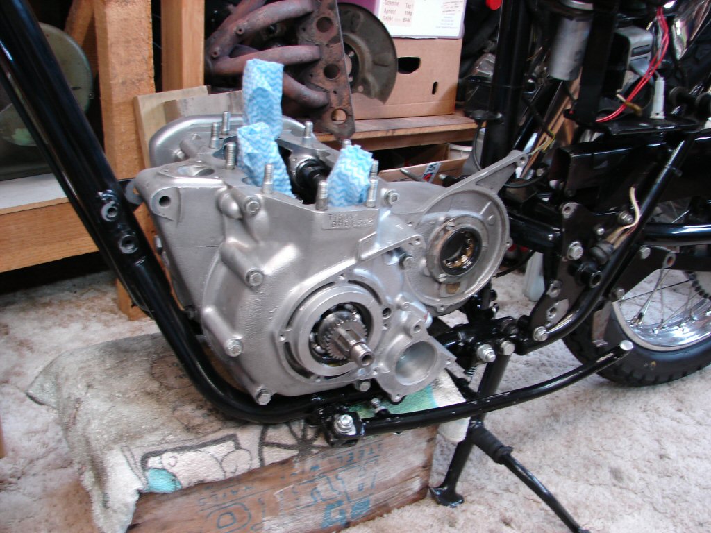
A few bolts and it becomes self-supporting. I have been looking forward to this point for some time. We stripped this thing down in January and it has taken until now to get everything machined or acquired. Hopefully we have it all. I have spent some time today dragging cartons out of the loft - all the sub-assemblies are usefully contained with their respective fasteners, but all will need cleaning and various amounts of preparation before fitting.
Never mind - on with the show.
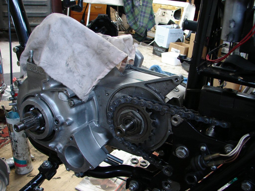
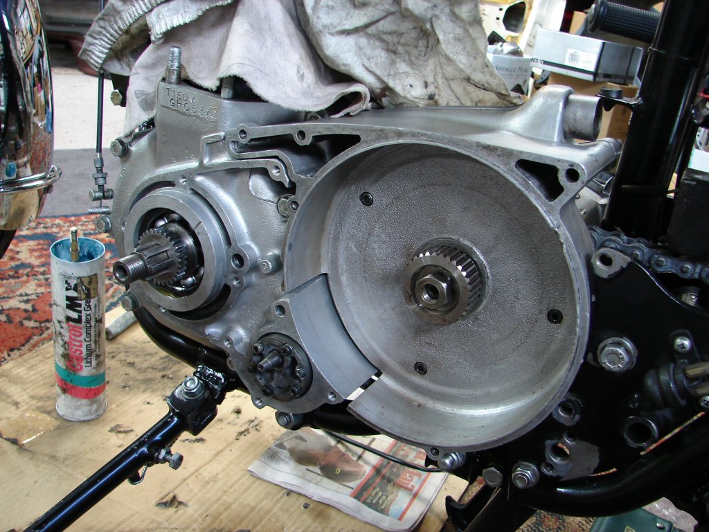
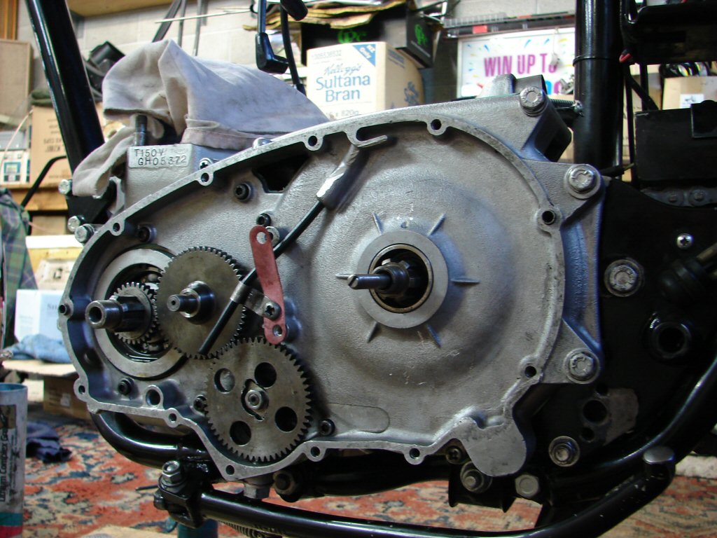
So good to see a lump in this space..
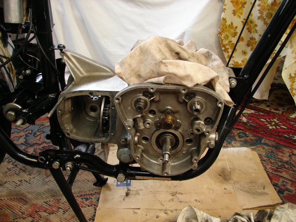
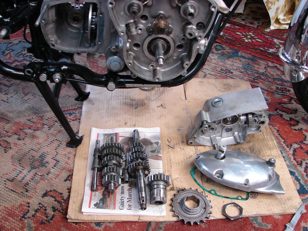
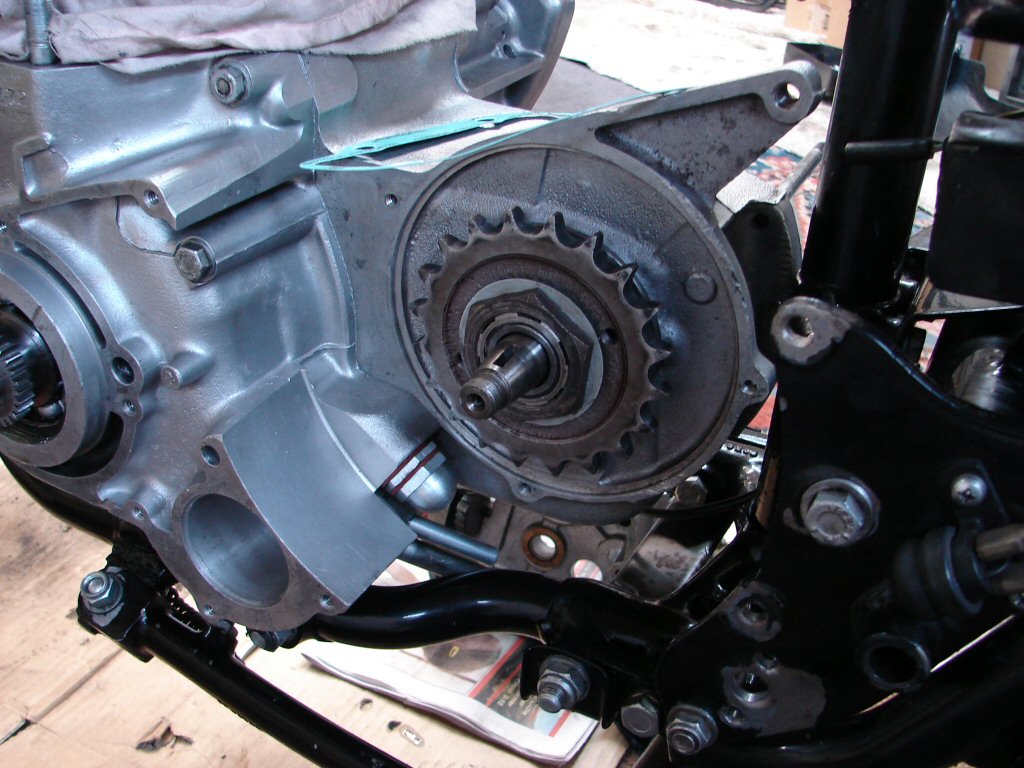
Next step is to reassemble the gearbox and final drive. The gear clusters are still nicely oily and sitting exactly as they came out albeit facing the other way..
Now - lets see... that high gear assembly goes in first, and the sprocket mates to it after a coating of sealant to prevent oil getting out between the two. There is a lockwasher and monster nut to hold the pair together, so for now I will just tighten them as much as I can without having to lock anything up.
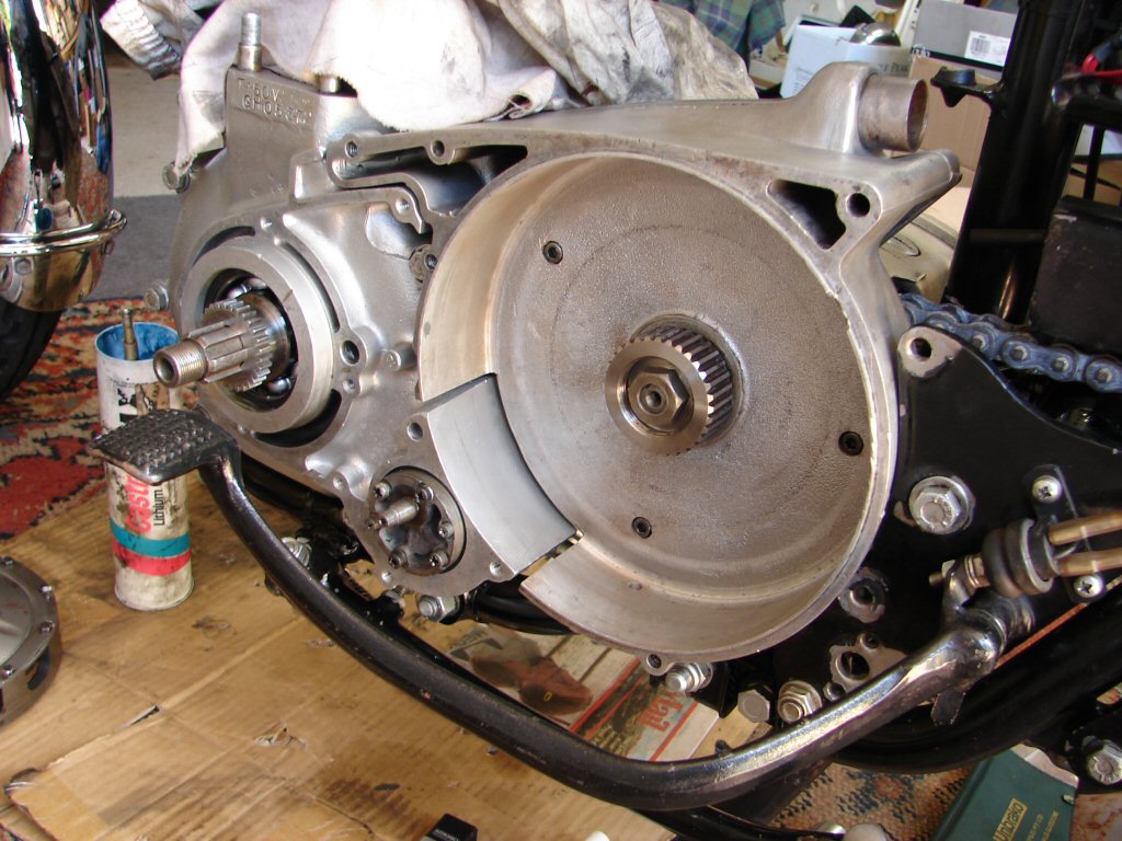
Coggery.
So thats what happened. Nice easy manoeuvre and everything happy to be in place. I trial fitted the mainshaft cluster to make sure all was as it should be.
Another hole plugged.
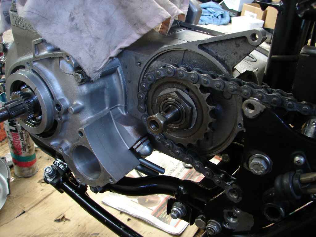
All shafts and gears are now fitted, selectors engaged with the camplate and the slector shaft fitted. Only other item here is to refit the layshaft circlip and slide the first gear dog up against it. That should now be ready to fit the inner cover.
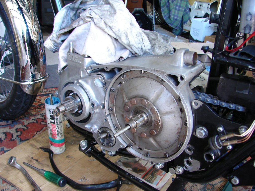
Closure imminent..
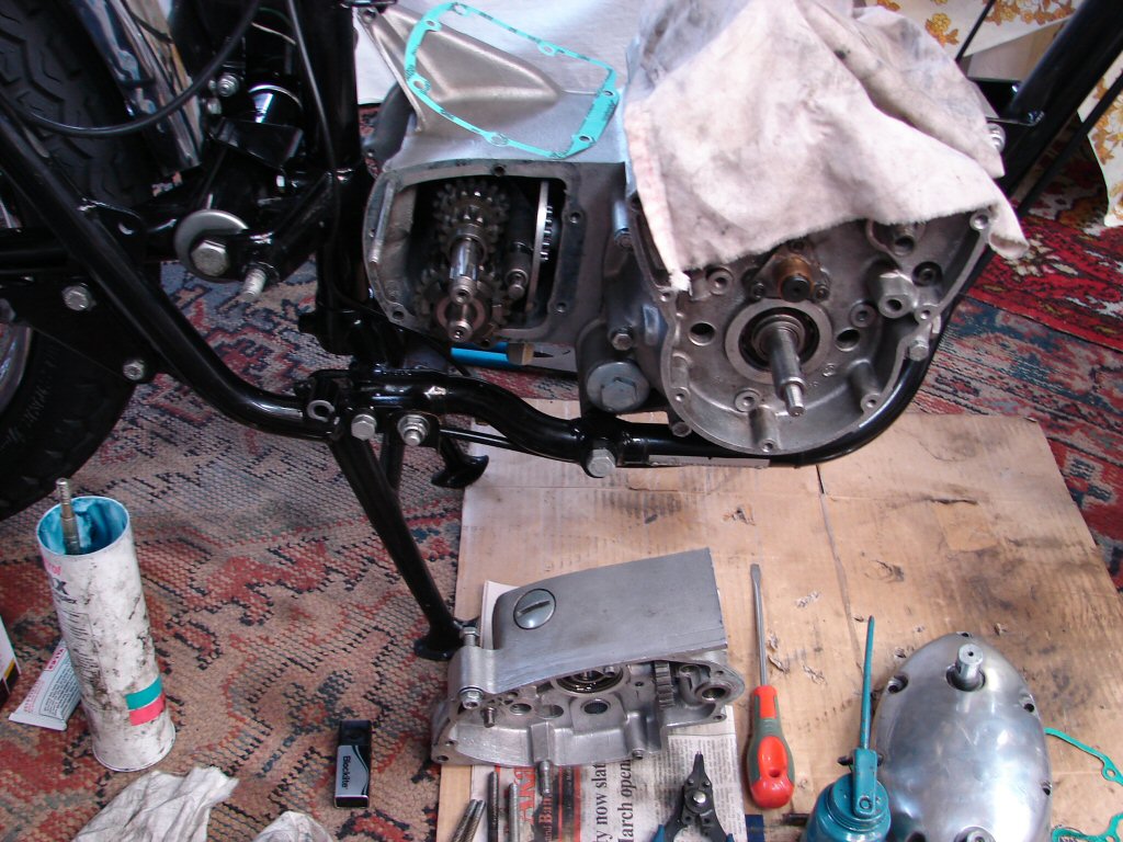
I fitted the inner cover, then trial fitted the outer to check that I had correct gear selection. I didn't. I could tell that the quadrant was not able to travel far enough, so that meant it had been slightly too low at the outer end on the first engagement. I loosened the inner cover again and pulled it out by 1/4" which allowed the quadrant to be repositioned. I raised it by the mesh of one tooth, refitted the outer case and tried again. Five gears at home.
Feeling suitably chuffsome that all was now correct, I completed tightening the inner case and the engine mounting plate as well. I fitted the kickstart pinion assembly and the nut and lockwasher, once again just tightening as much as possible by hand.
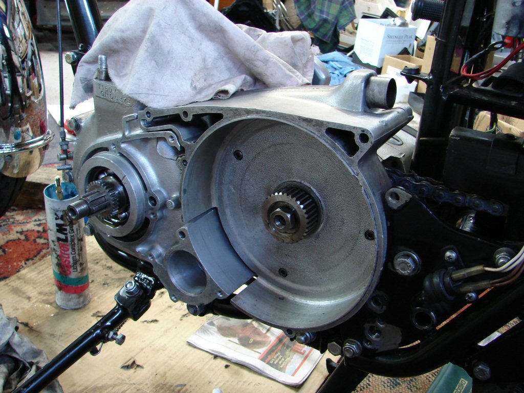
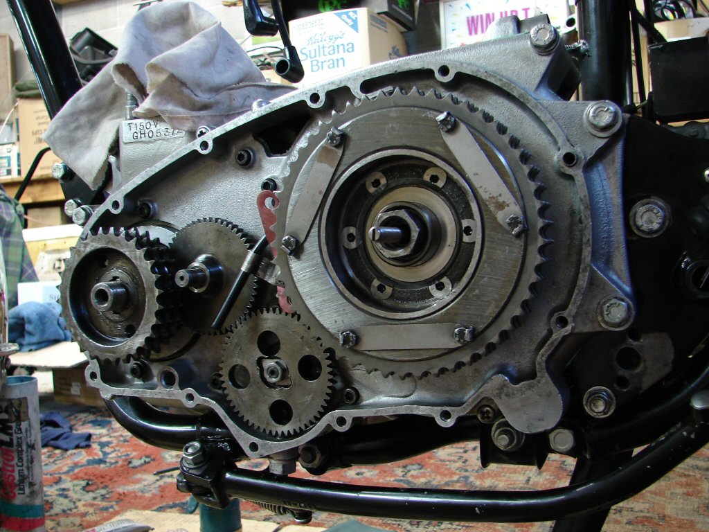
That - is starting to look business.
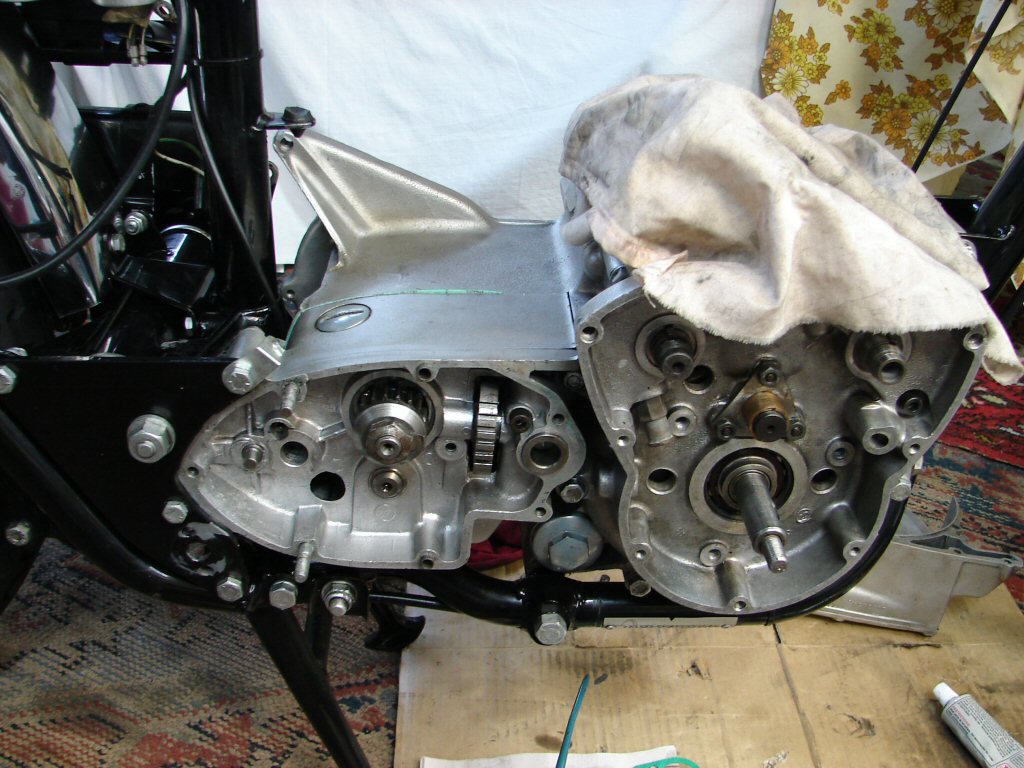
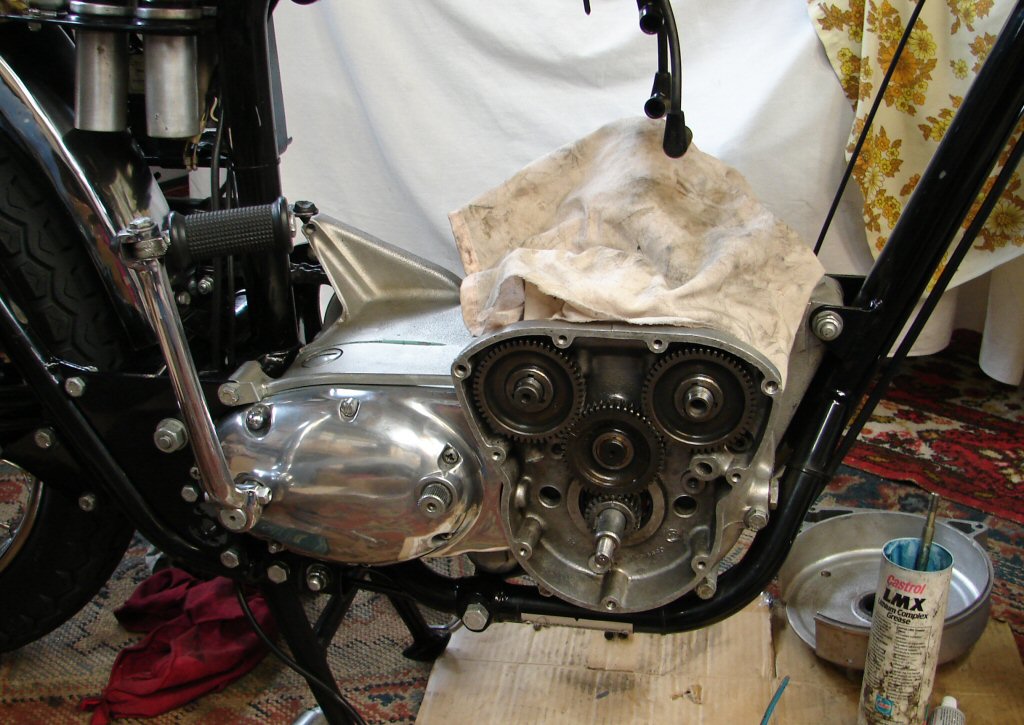
Tightening the nuts either end of the gearbox mainshaft is simplicity itself. Simply engage first gear and tighten one against the other. This was done and their respective lockwashers applied. This allowed fitting of the outer gearbox cover. I also fitted the crankshaft timing pinion and trial fitted the timing gears. I am not sure which gear was inlet or exhaust, so it is a matter of examining all the marks and deciding who goes where and which marks to give credence to.
Yes - I polished the gearbox outer cover. One needs some encouragement to continue the fight from time to time, and the sight of this gleaming alloy does the trick.
I think this is going to be a very cool bike.
I fitted the rear chain and cleaned up the clutch cover and its mounting screws. Then I had some doubts about the oil pressure relief valve. There had been two springs with it, and it had made a pilgrimage with parts from another engine rebuild by mistake - so I had chosen what I thought were the correct bits when I reassembled it. Now I was close to concealing it I felt a tad uncertain - so plucked it and stripped it again to see if I needed a plan B. At this point I have not made a decision - one needs the light of day to clarify such things. So tomorrow will reveal all.
Otherwise fine...
Cleanest it will ever be..
My dilemma with the oil pressure relief valve was to do with the fact that there were two springs with it. It would not have been unlikely that a new one had been added to the mix seeing as how this engine did some extreme things. In the absence of the owner who has supplied most of the parts, I needed to make sure I was happy with the choice of parts before the thing was obscured.
Parts in question.
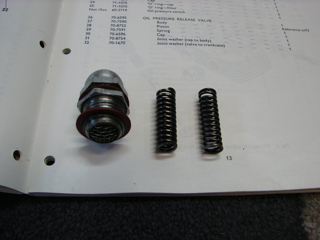
Most fortunately, I had a vague recollection that I had posted something about this on the "Triplesonline" forum, so I went back through my postings and sure enough found my description of a simple method I had used to determine which spring had the greater compression resistance, and had thus fitted the item that won.
Having now dragged all the various boxes of assorted bits of this bike out of storage, I had ascertained that the other spring must in fact be the oil filter spring, so that explained the mystery - and as I had in fact refitted the correct spring when I made the comparison, I simply did so again and put the blighter back in place.
Ready for the clutch cover.
The three screws that retain the clutch cover would create mayhem if they ever loosened in use. These three had been replaced with allen screws at some previous time, which gives some reassurance as one is better able to tighten them than some gouged phillips head screws.
However, I decided that I would also apply some form of thread retainer to clinch the deal. I figured that loctite was possibly overkill, and chose to use the same silicone sealant as has been used on the crankcase joints - and as there is a tube of it laying around..
Cover in place.
Next I would fit the oil pump, so it would now be necessary to complete drilling and surfacing the end plate, and whilst I would be setting up the drillpress to perform the operation, I might as well drill the oil tank filter as well.
So I did.
I checked the size of the expanded hole in the rear of the oil pump cavity where the larger pipe had been fitted, and found it to be 19/64"ID, so I used that size drill to open up the end plate first, then having mounted the oil tank filter in a vice with soft jaws, did the same to that. It then took some serious cleaning to ensure that all the swarf from the drilling process had been removed from inside the filter.
The end plate was now surfaced using several grades of paper on a flat surface - I did not go too overboard, but got the result I was after.
The oil pump itself was completely stripped and cleaned to ensure no christmas tinsel had gotten in after the big end went bigger. All happy now.
Another manoeuvre completed.
Something I found interesting. The oil tank filter had been undisturbed until now, and I plucked it from the tank and set about cleaning it up prior to drilling it. My cleaner of choice - CRC CO contact cleaner in aerosol form - does a fabulous job of removing any oil residues in seconds, but there was an area at the base of the filter that would not clean. When I applied a small copper wire brush, I found it to be a fluffy fibre-like material which had infiltrated the gauze filter. The only source I can think of is oil filter medium. It would seem that an oil filter had begun to disintegrate whilst running, and whether this was in response to the increasing trauma of the impending rod failure - or simply in the due course of things - it would now be impossible to say. Not something I have encountered before.
The oil pump was reassembled and flushed with oil. The new gasket supplied with the gasket set was too large for the oil pump cavity, so I spent some time sanding around its edge until it was happy to comply. In these restricted spaces a deformed gasket can be enough to prevent an effective seal - so never assume it will be fine. Make it so.
Oil pump fitted and o ring inserted - although it is hardly visible. I also fitted the key into the gearbox mainshaft and loosely fitted the clutch hub. I will fit the rear brake pedal and reinstate the brake in order to tighten the nut.
Not much progress but many things resolved.
So - the rear brake got reinvented and the clutch hub nut got tightened - with a moderate amount of loctite. The hub is keyed to the shaft, so it is really only to prevent the nut from rattling itself off the shaft - not like it is under stress.
The clutch hub also has a light smear of high melting point grease applied - it is not really visible - so that is the correct amount...
Ready for a clutch..
The clutch was not a problematic assembly on this bike, so it was adequate to just reinstall it. There were no signs of any oil ingress, but I decided to replace both oil seals anyway. These would be the seals at the shock absorber to clutch joint, and the clutch pullrod.
The clutch assembly - genius or achilles heel..?
Next step is to fit the primary inner case. This one has had some welding done around the oil pump idler gear shaft. Turns out this is not the correct inner case for this engine - it has come from a very early model hence the extra casting material at the bottom. When I trial fitted the case it was obvious that it would not sit flat against the crankcase and/or clutch cover. A test with a steel rule showed that the case had distorted at the area of the weld, and would need some relieving in order to make a happy joint.
With judicious use of a pair of files I was able to remove a bit of alloy in this area and the case then mated happily to its adjoining surface. The fact that nobody had bothered to do so in the first instance says a lot.
Time to go straight.
I was now able to fit the inner case on its new dry gasket. Everything tightened up as it should. I also fitted the oil pump drive gear and engaged the lockwasher. The idler gear fitted precisely, which at least indicated that the welding job was done with some precision - even though it had removed the presence of one allen screw position.
Chain oiler tube fitted along with the gasket which ensures equal spacing between primary outer and inner cases.
Engine mounting complete.
Next job would be to verify the alignment of the primary chain. There have been repairs made to the centre of the spider on the cush drive, so it seemed advisable to check that adequate consideration had been given to alignment after the machining processes.
I fitted the front sprocket against its shim, and bolted the rear sprocket/cush drive far enough onto the clutch cover so it could rest in its operating position. The outer case was fitted with a new gasket and the cush drive assembly pulled out against the outer cover. Outer cover was then removed and measurements taken of the distance from the inner case outer edge to the outer edge of the front sprocket. This was compared to the same measurement to the outer edge of the rear sprocket/cush drive assembly. I could not measure any discrepency with my vernier, so I felt somewhat reassured that at least somebody involved with the previous build of this engine knew what they were doing.!
So that's nice.
Best check the cush drive rubbers next..
This day I decided to bite the bullet and begin my least favourite job of cleaning stuff. In this case, the oil tank and some of the oil lines. I find this rather tedious, especially as it means lack of forward progress, but is simply a necessary part of the equation.
I used petrol to initially sluice the oil film and debris away, then resorted to my normal cleaner which strips any remaining grubbage. I finished with compressed air which also dislodges any paint that is planning to leave town in the near future.
I used a piece of cardboard to drain the umpteen tank flushes onto in order that I might ascertain when I was reaching a point of being clean.
Kaleidoscope of dangerous particles..
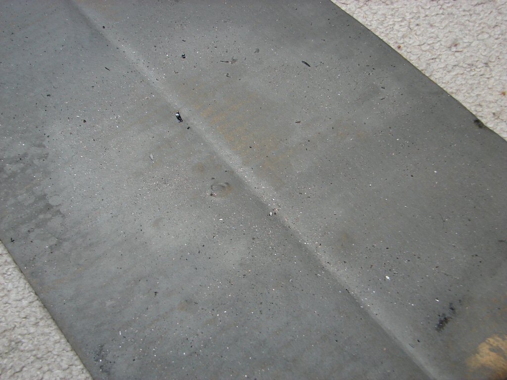
It takes a very concerted effort to get to a point where you would feel safe about returning an oil tank that has been subjected to contaminated oil back into service. It can seem that it will never be clean. After doing all of that I refitted the tank to the bike, as I would like to get some oil into the engine fairly soon. Even though it may be some time before running it is imminent.
I realised at some point that the oil line I was flushing - and which was extremely clean, for which I was thanking the tank mounted filter - was now actually obsolete. Because the inlet feed pipe has been opened up to 5/16", neither the line nor the top pipe were now applicable. It would be rather pointless to utilise anything other than the largest possible line to enjoy the benefit of the new expanded port into the oil pump.
Checking the parts books it seemed that the logical approach would be to purchase the T160 top pipe which was designed to be the correct match. A T160 line would also complete the transition.
A number of parts had already been identified as needing replacement. The left-hand threaded nuts that retain the timing gears to the camshafts were in such bad condition that I would not re-use them. It would seem that the term "left hand thread" had been lost on some previous practitioner, and I would not risk damaging the camshaft threads. The previous piston circlips had been tossed, so a new set was required. Whilst I had stocks of o rings and seals to use, replacements were needed to maintain stock levels. I placed an order with L P Williams in the knowledge that there would now be a delay while these parts travelled halfway around the planet.
I did not deem it necessary to specify in which direction they should travel - I figure I can re-orientate them when they arrive...
Very rewarding to see spaces filled..
Time for Part II