Cam Timing on Triumph Trident and BSA Rocket 3.
I had found that the recommended method of accurately setting the cam timing on these old triples involved a lot of equipment that I did not possess, and even when I borrowed everything that was suggested I was not sure that I had managed the best result because the measurements were so small that there was a large margin for error.
In 2017 I was undertaking a complete rebuild of a T150 Trident engine that had suffered major damage, and I had decided that I could not afford any errors if this thing was ever to enjoy a long reliable life. This meant that a high degree of quality control was necessary.
When it came time to fit the cam gears and time the camshafts I found that there were no marks which looked like "factory" that made much sense, although there were a number of hand scratched marks that had been made by some previous builder. I would need to start from the beginning.
I was aware that a method known as "lobe centre" timing could be done while the cylinder head was absent, as it only required careful measurement of Top Dead Centre (TDC) and the midpoint of full valve lift of both camshafts. This sounded doable using much less in the way of specialised equipment - so this is what I did.
In my T160 workshop manual I found the following figures for valve timing;
Inlet opens 50 degrees Before Top Dead Centre (BTDC).
Inlet closes 64 degrees After Bottom Dead Centre (ABDC).
To ascertain the midpoint I would need to halve the duration of the entire time the valve was open and add it to the start point - that is - 50 degrees BTDC
So - 50 + 180 + 64 = 294. This is 50 degrees to TDC, then 180 degrees which gets us from TDC to BDC, then the 64 degrees after BDC. Half of this is half of 294 which is 147.
Therefore, the time at which the valve would be exactly at the midpoint of full lift, as that is "lobe centre", would be 50 degrees BTDC plus 147 degrees. Removing 50 from 147 gets us to TDC, and leaves 97 - so the point we are after happens at 97 degrees After Top Dead Centre (ATDC).
By the same method, the exhaust figures for valve timing are;
Exhaust opens 67 degrees Before Bottom Dead Centre (BBDC).
Exhaust closes 47 degrees After Top Dead Centre (ATDC).
To simplify the process, these figures also need to be related to TDC as that will be our main reference point and the one we can reliably return to at any time during the procedure.
So - 67 + 180 + 47 = 294 once again. Half of this is 147 again. If we add 147 to 67 BBDC - we remove 67 to get to BDC leaving 80. As there are 180 degrees between BDC and TDC this means our midpoint occurs at 100 degrees BTDC.
Now - you do not need to understand any of the above. I have only described it for the benefit of those who may wish to argue the point. I have carried out all of the above and the results speak for themselves. All you need to know is the end result and how to apply that to your cam timing. That is what I shall now describe.
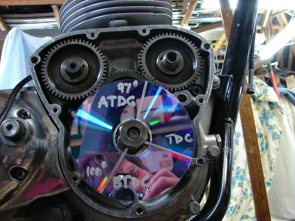
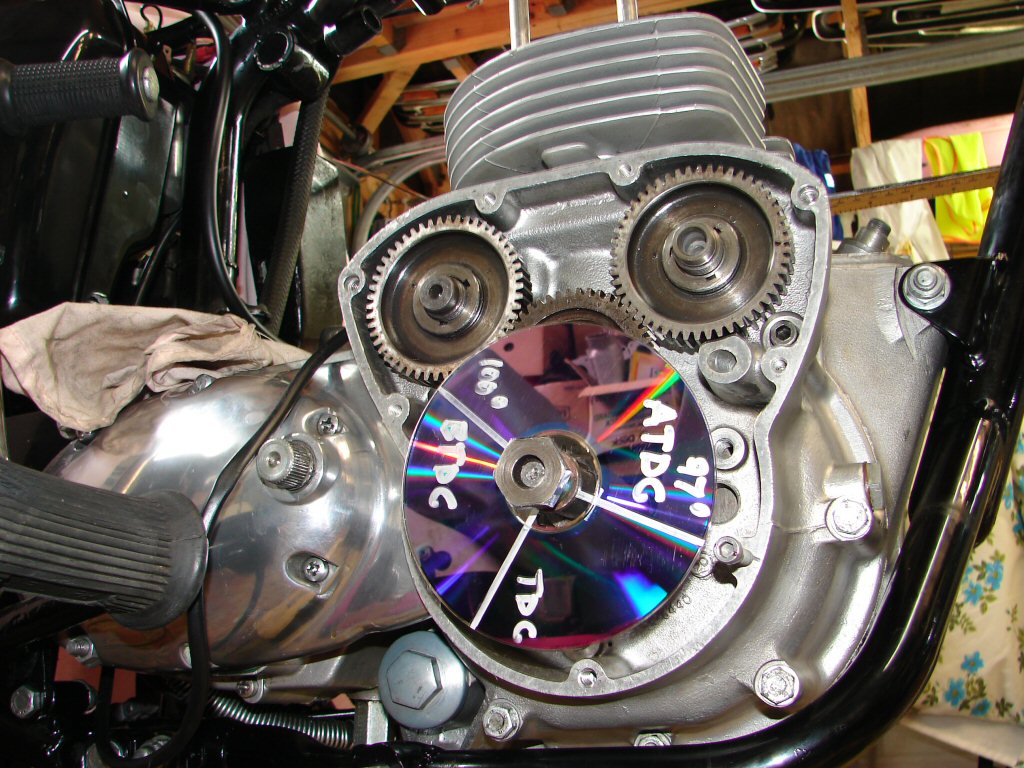
As I do not have a degree disc I made one. I used an old DVD. Using a protractor I marked three lines which radiate from exact centre. First I drew TDC. As the disc can be positioned anywhere on the shaft it matters not where this line is - just assume this is going to be the reference point.
Next I drew a line which was 97 degrees anticlockwise from the first - this is going to be 97 degrees ATDC.
Finally I drew a line which was 100 degrees clockwise from the first - this is going to be 100 degrees BTDC.
I used a marker pen whose colour gave the best contrast for viewing and photographing, so it ended up being a rather thick line. I just made sure during my readings that it was the exact centre of this line that I used to match things up. If you have a proper degree wheel you can simply locate the two points and mark them so they are easily visible.
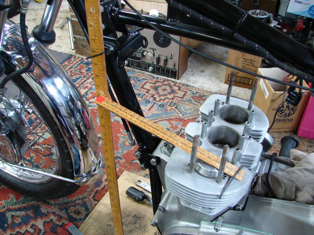
Regardless of whatever form of cam timing you undertake, the most critical thing is to know that you have absolutely identified TDC. While the piston rises and falls with the rotation of the crankshaft, there is a period of time during which the big end bearing at the bottom of the conrod is not going up or down much but mostly sideways. This means that if you are observing the top of the piston you need to turn the crankshaft forward and back to observe the points which result in the same amount of up and down travel in order that you can establish what is halfway.
I achieved this by attaching a wooden ruler across the top of the piston, as the tiniest amount of vertical movement of the piston resulted in a large deflection at the far end of the ruler. Rocking the crankshaft to and fro by turning the front sprocket allowed me to watch the ruler and find the midpoint. Having done this I then fitted my degree wheel and arranged a pointer close to the edge. As it happened the size of my degree wheel DVD allowed the use of a screw in one of the timing cover retaining holes that neatly sat right near the outer edge. This is also visible in the above photo.
Note also that TDC on the drive side piston coincides with the timing dot on the crankshaft pinion being at the 12 o clock position, so all measurements involve the drive side piston and cam followers.
Below is the arrangement for positioning exact TDC. I used a yard ruler at the end of the foot ruler so I could more easily see the smallest movement.
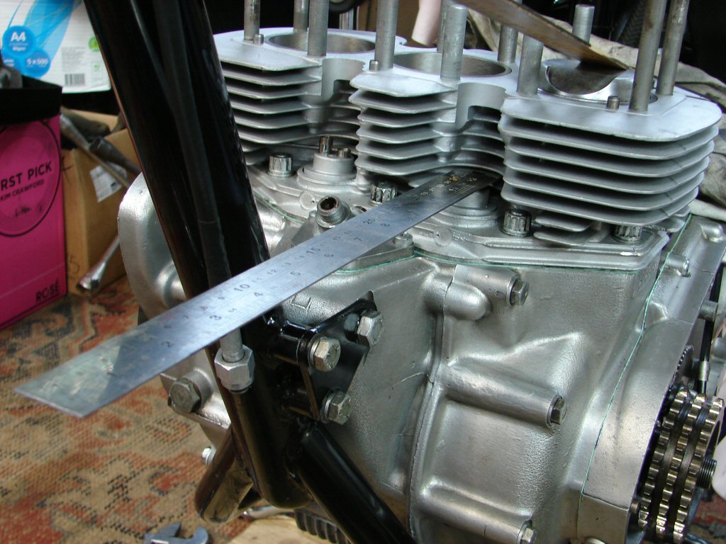
With TDC nailed I now needed to ascertain when the cams were at lobe centre. This could be measured by watching the rise and fall of the cam followers. The use of a steel ruler this time would mean that the weight of the ruler would make sure the cam follower dropped as soon as the cam lobe allowed it, so there would be no error caused by friction in the cam follower action. Moving the crankshaft showed that the response was immediate and repeatable.
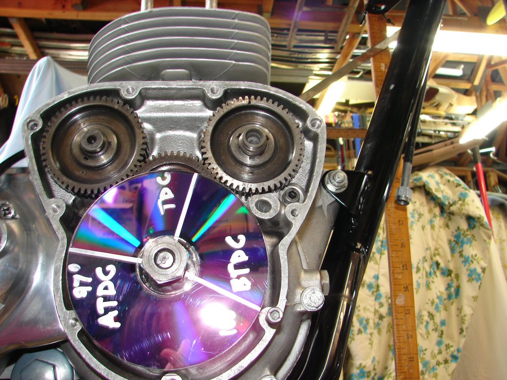
In the top photo you can see where the camwheel keyways are positioned. When I assembled all the gears I had a rough idea where things should have been because of how I remembered it to have been when I pulled it apart, but the actual timing marks were not clear. If you consider the relative positions of the marks on the degree wheel, the exhaust lobe is at midpoint before TDC and the inlet is at midpoint after TDC. This means that the piston in question must be on the exhaust stroke, as the exhaust valve is open max as the piston is coming up, then the inlet is open max as the piston is going down, thus drawing fuel for the next firing stroke. This is not of any consequence, but it is where the factory set all the timing marks when there were any.
As I had placed the steel ruler on the exhaust follower I did that cam first. Rotating the crankshaft backwards I watched the ruler rise to quite a radical angle where lobe centre was going to be. When I rocked the crankshaft to and fro I was able to see the midpoint of the period when the ruler had reached max lift and was not moving. When I went around and checked my degree wheel I was amazed to find that I had fluked it and actually found the magic 100 degree BTDC mark.
Perhaps more importantly, when I went back and rocked the crankshaft and found the mid point again, the marks were perfectly lined up again - so it was a repeatable process.
The inlet cam tends to be the more critical one in my experience, especially with T160's as they had their cam timing retarded slightly to begin with. On this engine I simply had no idea where the timing marks were as they were not visible, and the various scratches made by others could not be relied on. However, I was starting with the cam and gear in a similar position to the exhaust, and that had gone well.
This time I rotated the engine forwards until the steel rule which was now on the inlet cam follower had reached max lift. When I checked the degree wheel I found that it had travelled about 1/4" past the 97 degree mark, meaning that the cam was retarded.
I returned the engine to TDC and removed my degree wheel. I then removed the intermediate timing gear whose circlip had not been fitted yet for this potential reason. I moved the inlet cam gear forward (clockwise) by 1 tooth and refitted the intermediate gear. Now I had to go back to finding TDC in order to refit my degree wheel at that reference point.
With this done I rotated the engine forward until I had mid point of max lift on the drive side cam follower again. Now when I checked my degree wheel it was about 3/8" before the 97 degree mark, so now it was too advanced. My desired point was somewhere between the two.
Fortunately, Triumph understood the necessity to get these things right, and manufactured the cam gears with 3 keyways, each being roughly 1/3 of a tooth displaced. The answer would now be to try the other keyways in order to get our 97 degrees.
Once again - back to TDC - remove degree wheel and intermediate gear. This time I also removed the inlet camshaft drive gear making sure I did not move the camshaft. I then rotated the gear anticlockwise until the next keyway lined up with the key on the camshaft, and then slid the gear back on. I had to rotate the camshaft gear very slightly anticlockwise to get the intermediate gear to engage, which I figured was a good omen as this meant it was being retarded slightly.
Start again. Find TDC. Refit degree wheel aligned at TDC mark. Rotate crankshaft forwards to max cam follower lift midpoint. Check degree wheel.
Spot on.!
The steel ruler can be seen at a steep angle behind the barrels heading up above the toolbox. With such an extreme range of movement it makes finding the midpoint quite an easy job.
If my last adjustment had not been successful I would have tried moving the cam gear 1 tooth in the required direction, and if that had failed I would have then used the third keyway in the cam gear and started over.
Every new start must begin with finding TDC and aligning the degree wheel, otherwise any settings are doomed to be incorrect.
Hopefully this simple means of getting accurate results may be repeatable by any of you who are game enough to follow suit.
Having no valve springs in the mix means that everything stays exactly where it was when any gears are removed, so that makes life much easier.
I am extremely pleased with the performance of the engine this process was pioneered on, and the throttle response is quite remarkable for what is mostly a stock 750 unit.
I can be contacted via the Triplesonline website if anyone has questions.
Go well, Kilroy.