November 2020
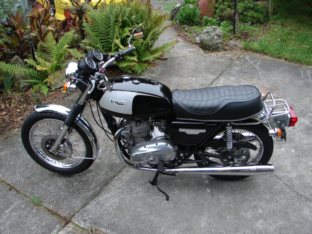
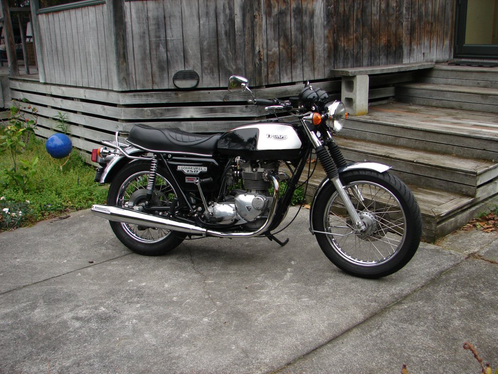
1979 Triumph T140 Bonneville 750
This tasty T140E came back with an electrical problem which I was hoping I had sorted. It had a history of lacking sufficient charging to complete long runs without its battery losing ground to the point of stopping. I had previously found some issues which had effected the Zener diode operation, but despite fixing that, there was still a problem.
I began by checking everything I could with a meter. The alternator checked out ok as regards having good insulation and normal readings, the rectifier was certainly ok, and all of the gubbings connecting them together was also seemingly above suspicion. However, running the engine still showed there was a lack of power from the alternator. Which lives in here...
After removing the outer case and the rotor retaining nut I was suddenly surprised by the spacing of the rotor. It appeared to be too far recessed inside the stator. Surely this would result in less than optimum output.
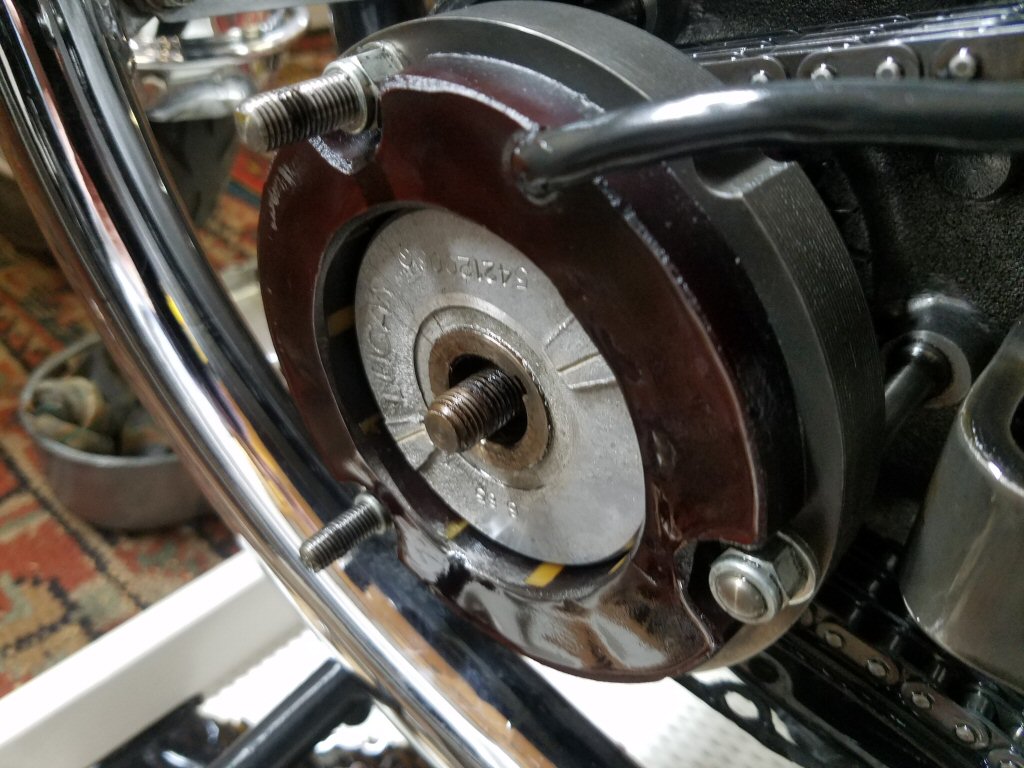
Looking down from above, the rotor magnets can just be seem inwards of the stator, and the laminations of the stator do not even reach the inner edge of the windings.
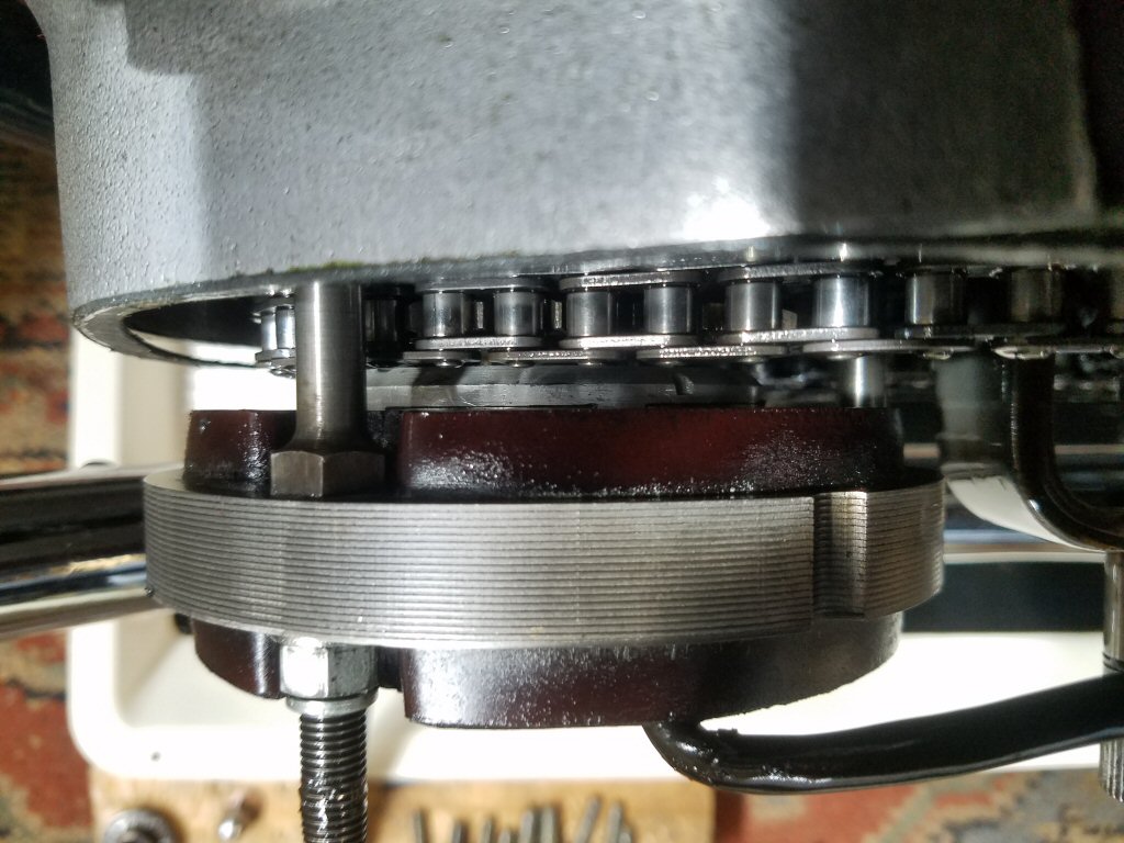
Experimenting with various spacers soon showed that it was not possible to bring the rotor further out, as there was not enough thread left to retain it to the crankshaft. I made some online queries only to be told - "they're all like that..". Oh well, keep looking then.
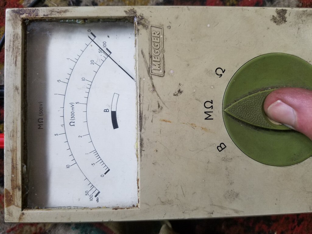
Think. Your multimeter uses a battery of between 1.5 and 3 volts to allow you to check insulation. Even your 12 volt charging system develops more volts than that, so really, it is not going to tell you the entire story when things are obscure. Somewhere amongst my old electrical gear I had a battery 'Megger', which through electrickery could produce 500 volts in order to check insulation values with some degree of authenticity. I finally located it and found all its batteries had corroded long ago. So I set about cleaning all the contacts and managed to coax it into life.
To test insulation you connect your meter between either of alternator wires and earth - that being the frame of the bike. Like this.
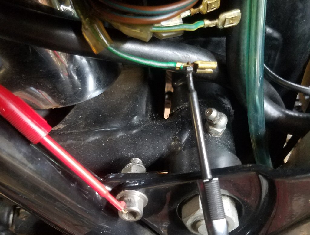
Now we will see what gives. If the pointer stays on the left of the scale, that equals very high resistance, meaning the insulation is good. If the pointer goes over to the right side (full deflection) then we have a fail, and the insulation has been damaged irrepairably.
Ladies and Gentlemen, we have a fail.!
This prompted the removal of the faulty alternator stator. Once removed it became apparent that the outer laminations between two mountings, that is one of the 3 windings, was noticeably blackened, indicating an internal meltdown. Seems we have found the culprit.
Fortunately for my friend, I had a brand new alternator which I had taken in part payment for a previous job where the alternator was not the problem, so I kept it as the sort of spare I would eventually find a use for. I just did.
It all fitted as if made for the job. Oh. Wait...
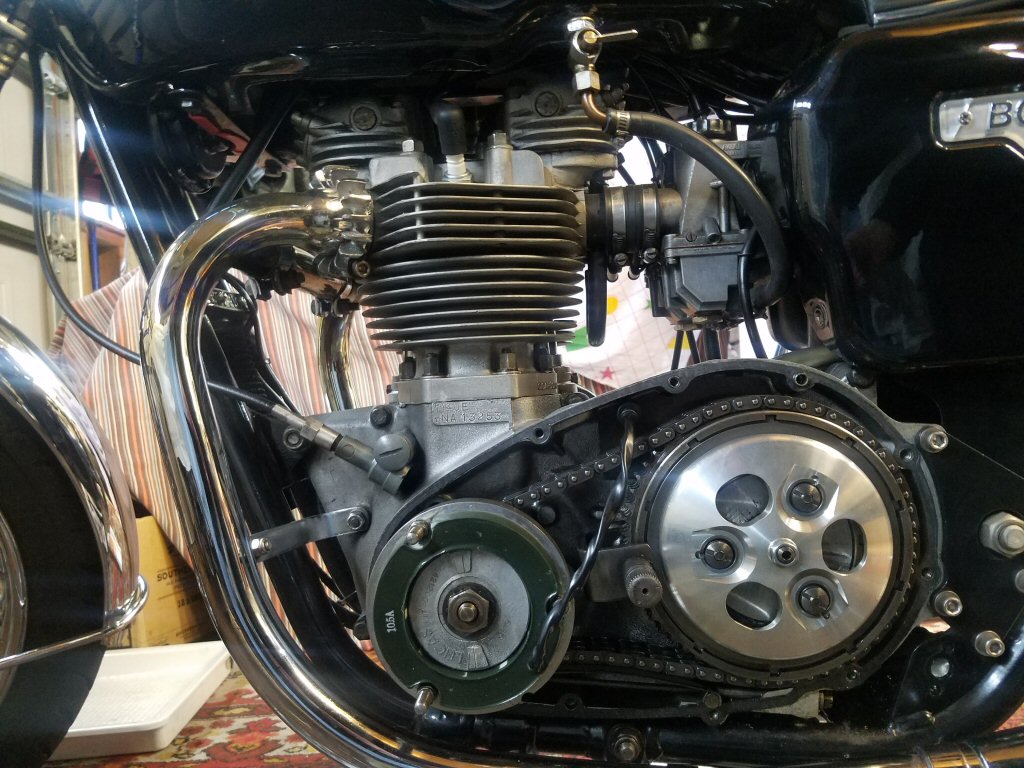
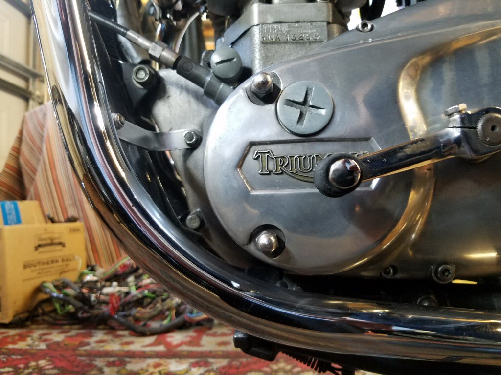
Notice the rather spiffing clutch cover plate on this bike. One of a number of tasteful mods it has received.
After restoring the wiring connections the bike was run up, and lo and behold we had charging voltage a tad over 14 volts. That will do nicely.
Nothing left but to button it all up and take the obligatory mug shots.
Alloy barrels and a Hyde 'bottlebrush' oil cooler. Choice period bits.
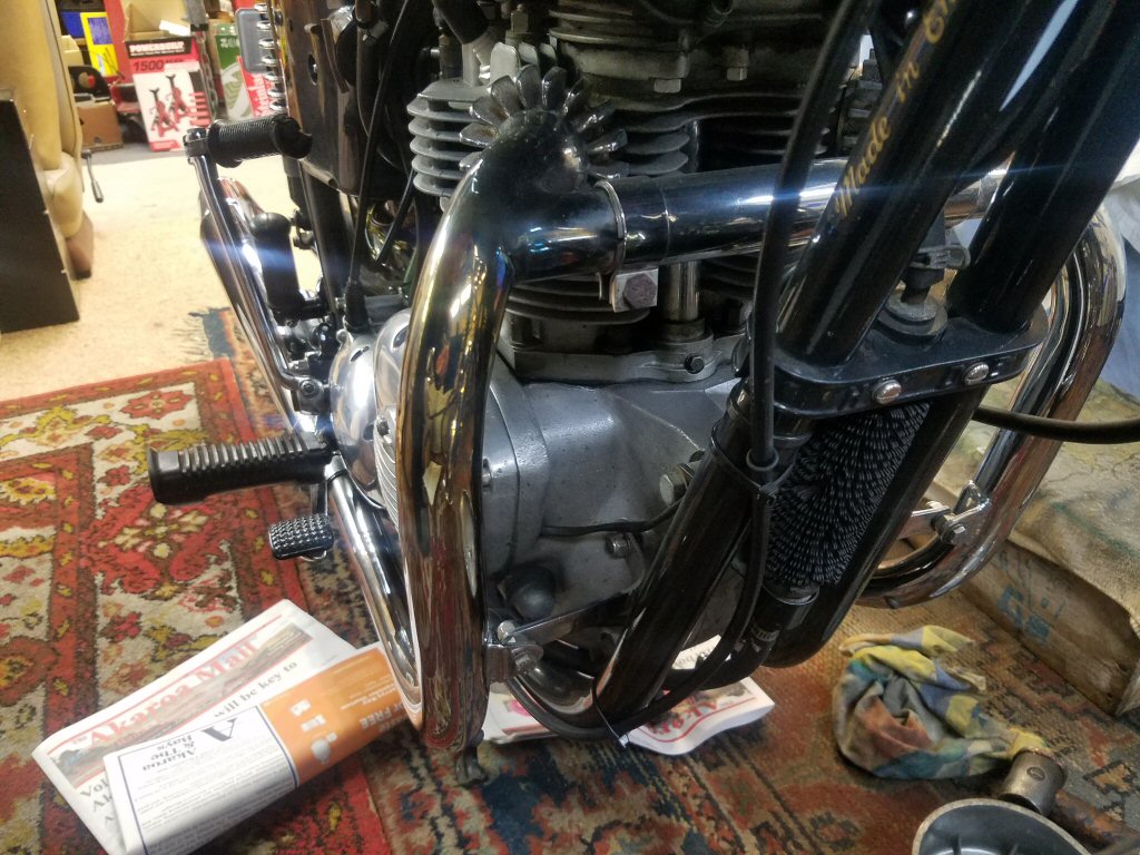
Isn't it a sweetie. Rides as well as it looks.
Well, that was fun. Especially as I won. Cheers.