October 2026
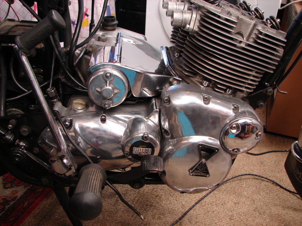
1975 Triumph Trident T160 750
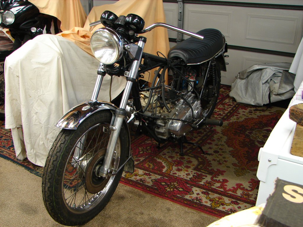
A friend had let me know that he would be interested in acquiring a T160 should I hear of one becoming available. I had not at the time, but shortly thereafter a mechanic who I knew through work phoned me to see if I knew anyone that might want his.
I had never seen the bike before, and it was not running at this time as it needed its top end put back together, but I arranged to bring my friend over and we would take a look.
This was how it looked then, being January 2022.
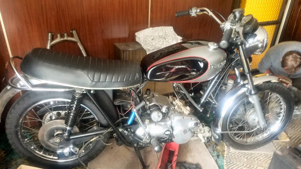
Yes - it did require some putting back together, but the cylinders were bored, new pistons present, and the cylinder head had received some mild port balancing So it seemed likely that the reassembly was the only thing left to do.
A deal was done and the bike changed hands.
It arrived here with various boxes of bits and we had a brief look through them to make sure the usual suspects were accounted for. Hard to appraise the presence of all the necessary parts until you are in the process of bolting them together, so there will be a discovery process.
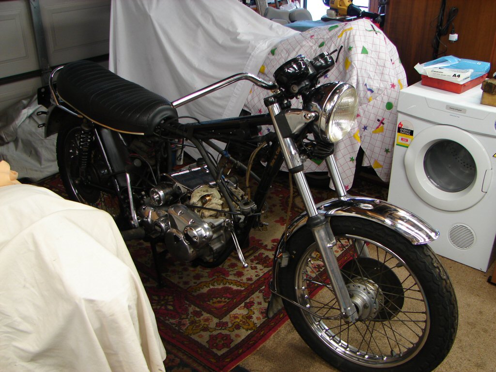
There was not much time left to go further today, but I did repair and refit the headlight just to instil some small sign of progress, although it will need some indicators fitted so it will need to come apart again later.
But meanwhile I had discovered while messing with the headlight that the instrument binnacle was loose on its mountings, despite the bolts being quite tight. I can't help myself but to put things right as I discover them - lest I forget later.
Removing one mounting bolt I found that the large diameter washer which compresses the rubber bushes was absent, and also appeared to be likewise on t'other. I took the bolt and other distance pieces and found the missing washer at the rear where there should be none, but a distance piece which was there. I cleaned the bolt and proper washer and refitted it, then repeated the process on the second side which was in an identical layout.
Now everything made sense and felt as it should, so I bunged the clocks in as they needed to be somewhere other than amongst the clutter on the floor.
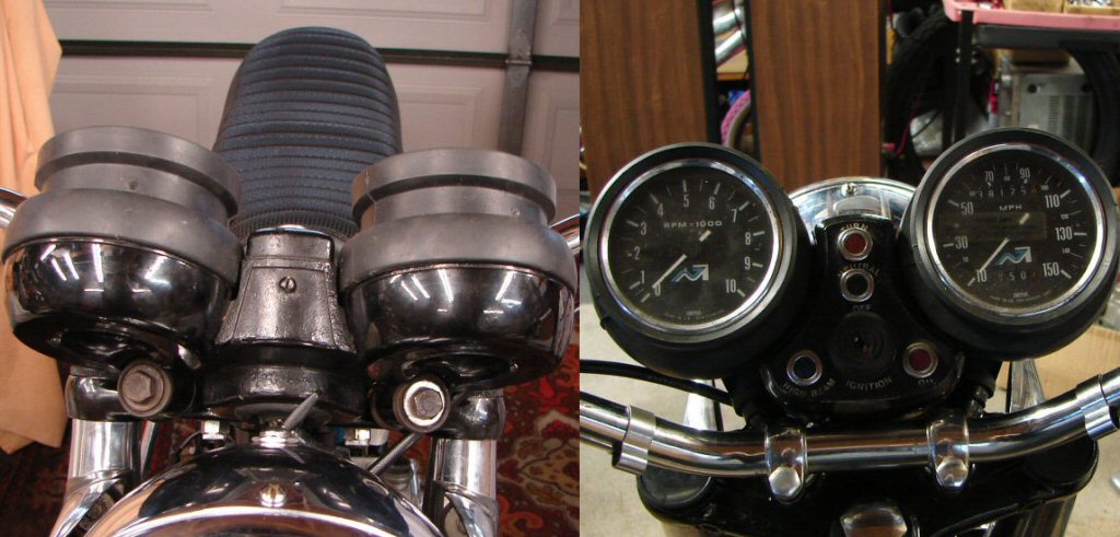
Yay - another small improvement.
Next job will be to remove the centre conrod to check the condition of the big end bearing. Odometer reads 38,000 odd in miles, so unless the bottom end has received attention earlier in life, I would be expecting the plain bearings to be down to their copper backing in places by now. My own were all worn as far as you would want them to go at 41,000 miles from new.
It is a most unwise practice to put a new top end on a worn out bottom end, as there will be tears at bedtime for sure. I have never tried, but I imagine that it may be possible to remove the centre main bearing caps via the crankcase opening, so it might be possible that they can be checked also.
We will see..
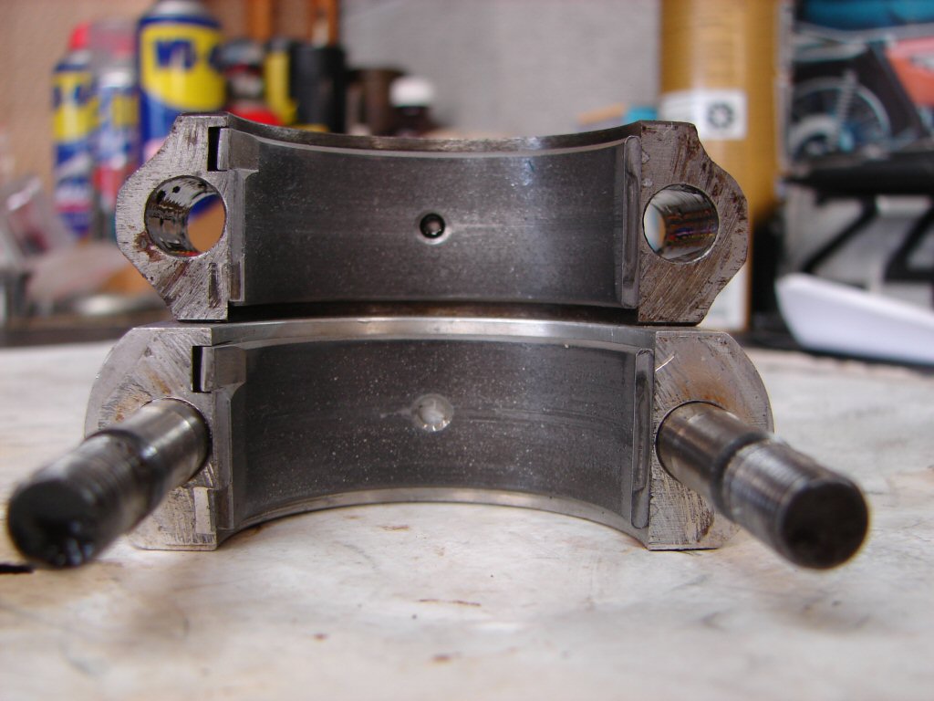
Well - we have good news and more good news.
The centre conrod was removed without fuss and to reveal that it has white metal bearings fitted, which means the bottom end has been rebuilt at some stage since new. From my observation these bearings have not been there very long, I would think possibly less than 5000 miles.
Even better, the shells are .010" undersize, so the crankshaft has also been reground. That might suggest that there had been an issue which prompted the rebuild, as these cranks are capable of higher mileages than 30,000 odd without needing a regrind at all.
It would be highly unlikely that the main journals would not have received the same treatment, so I shall trust they have and move forward. As soon as the barrels are on I will be able to do an oil pressure test and we will know more. Not having to disturb the bottom end is a huge plus.
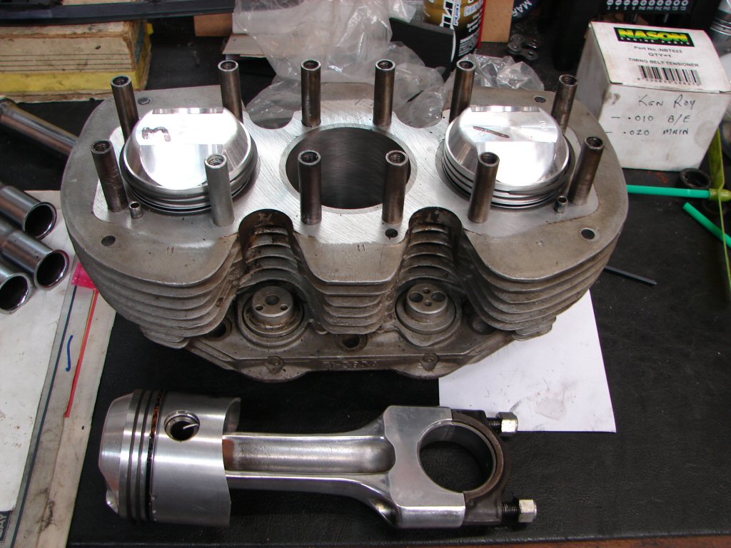
Barrels are next on the to-do list. I have fitted the centre piston to its rod as it will be inserted into the bore first and by itself. This is because the conrod can be tightened through the sump plate aperture last, thus reducing the fiddle factor. There are two ways I could do the rest - either by the traditional method of coaxing the pistons into the bottoms of the bores as the barrels get lowered over the top, or by inserting the pistons into their bores but leaving the gudgeon pin holes protruding out the bottom and just sliding the pins in as the barrels get lowered.
Pistons are .040 oversize, so the bores had required a good clean up from their previous life, as all oversizes would have been readily available when this work was done. Possibly the former life had a difficult ending.
Before we can proceed the cam followers will need careful scrutiny, and as they are all mixed up together I will see if there are obvious wear marks that may indicate any that specifically need to be paired to their original guides.
But first I decided to check the general condition of things inside the crankcases and the fit of the new base gasket. It all looked shipshape, including the camshaft lobes, although they would benefit from a clean and some long overdue lubricant. Perhaps in the reverse order..
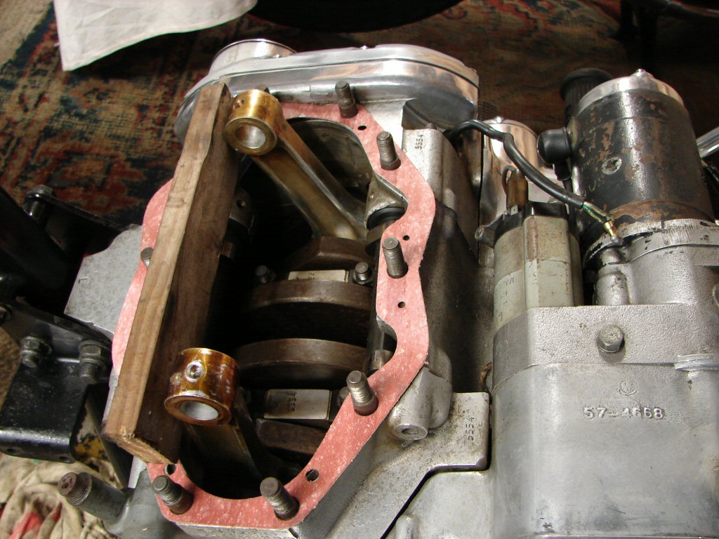
I also turned the crank to the position where the two outer conrods are at their highest synchronised point. This will be to check that there will be no unforseen problems if I choose to use the "fit the pins.." approach to getting all the slugs in their holes with the least stress possible. The tapers at the bottoms of the bores are minimal on this block, as are many. When having cylinders bored I get Glen to increase the taper somewhat, which makes getting the new rings compressed into the bores a doddle. As we do not seem to be doddlers here I am already favouring the above assembly approach.
Now back to the barrels and I identified another potential issue that needs be squeezed into this step by step puzzle. The rings were already fitted to the pistons before the bike came in, and as I never trust anyone else's engine prep I figured I could not fit any pistons without first checking the ring gaps. Usually they are fine straight from the packet - but if one should not be it is a recipe for disaster. It may have been done but it may not, and as my name is now on the ticket I shall have to do it anyway.
I hate sleepless nights...
But moving along - I decided to make sure the head gasket was going to fit without issues, as many have done. This 'new' gasket was probably purchased about 10 years ago, a time when their quality varied from one to another. Sure enough this one would not go anywhere near clearing the pillar studs and required quite a lot of 'easing' of individual holes, not because the holes were too small but because they were not in the right places. I spend a lot of time prepping these gaskets because I coat copper gasket spray on both sides prior to fitting the gasket on the block during assembly. The spray helps to seal any minor scratches on either head or block, and also seals around the oil drain dowels. It does not cause any problems during removal of the gasket which can always be re-used after annealing to soften it up. Obviously - having a sticky coat of spray on the copper gasket when you drop it on the block means you don't want to be fighting it to get it into place.
Once I got it happy to behave it was obvious that two of the oil drain dowels were not going to pass through their holes which also had to be addressed. Every bit of time spent preparing these parts pays off bigtime when you are in the throes of assembling for real.
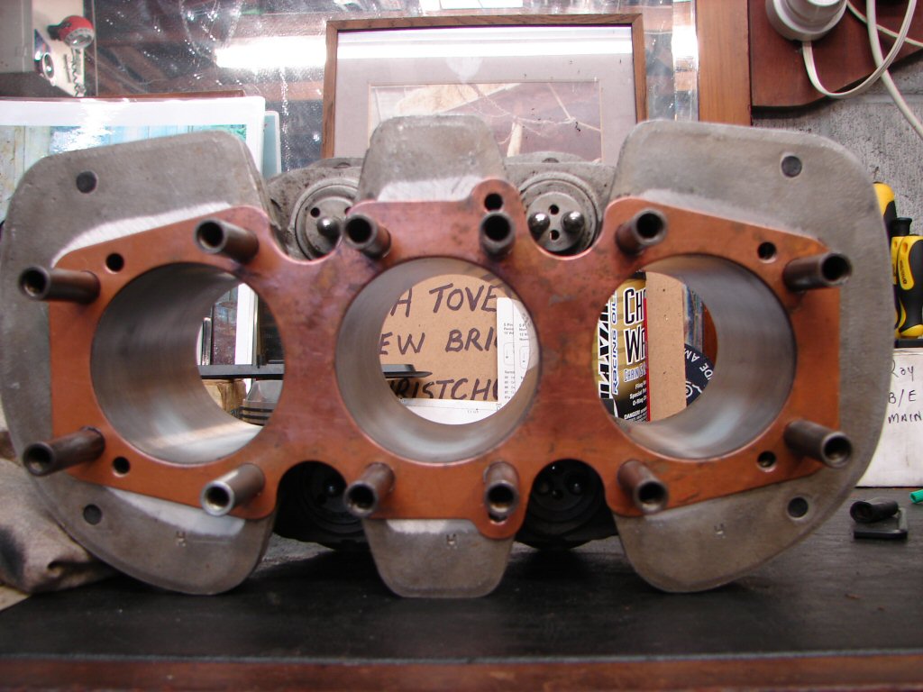
Just before the above pic I had spent some time sorting the cam followers to find their best places to reside, matching profiles and wear marks and testing their freedom of movement until I was happy enough with the final arrangement. They are visible in their guides here, but will come out to be oiled and a touch of assembly lube will be added to the operating surfaces. I then use small cable ties to hold them in place - last thing we want is one dropping into the crankcase as the barrels go on..
Not quite so obvious in the pic is another area in which the copper gasket can fail dismally - as this one does.
It is far more obvious from the below perspective when placed on the underside of the cylinder head.
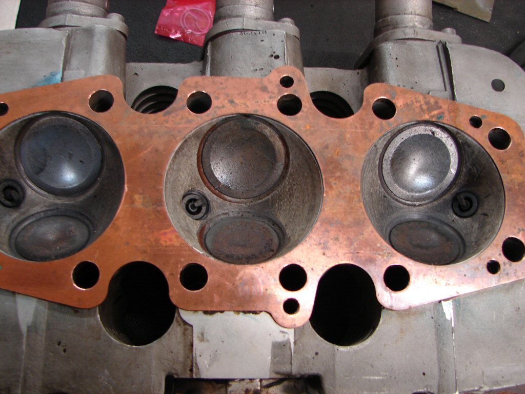
The exhaust pushrod tubes have to be threaded down a narrow opening in the finning of both head and block if the head is already in place. The bottom edge of the tubes is their widest part as it has to squash the bottom seal into a steel cup to make things oiltight. As can be seen - lower side is exhaust - there is no way the tubes are going to get through these gaps when the gasket protrudes so far into the opening. Yes - the head can be left off until the tubes are in place, but there are a number of tasks which are carried out after the engine is in service that are much easier done when it is only necessary to remove a rocker box and not disturb the head/block gasket joint, so this problem is far better sorted now rather than later.
There must be hundreds of T160 owners who have already fitted the head in place only to find they cannot get the exhaust pushrod tubes in - I know this because I have seen the mess they made of the gasket by trying to bend or chisel the excess copper off the gasket while it was in place.
I once was one of those people, and I have not fallen for the same oversight again.
The inlet tubes are usually much more compliant because there is a decent space between the gasket and the holes through the finning, so an appropriate angle can be adopted to manoeuvre the tubes past the obstruction point.
And here we have the cam followers fitted as viewed from the action side, with the best layout I could come up with by a lot of trial fitting. When dismantling a top end I keep all the cam followers and pushrods/tubes in the exact configuration they came apart, so they mate up best when going back together without having to sweat it. All the parts here were in bags and boxes together, so things may require several re-adjustings after they settle to new contours. Pushrods would be the most likely, but they all result in valve clearances opening up and thus need keeping an eye on for the first few hundred miles.
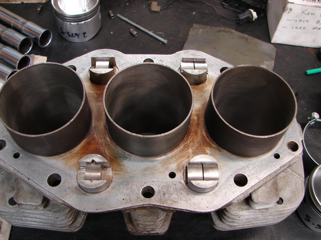
The head gasket got contoured to clear the pushrod tubes and it was trial fitted to the barrels so that I could test it in an honest fashion. Everything worked and the gasket got its corners rounded and edges smoothed so nothing looked out of place, and no areas of potential stress.
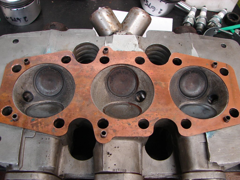
While the gasket has to fit over all the pillar studs on the barrels, it also has to fit over all the oil drain dowels in the cylinder head. The dowels have a flat end and a tapered end, so the flat end is driven home into the head, and then the tapered end does not create problems during assembly as the tapers find their way through the gasket and into the holes in the barrels easily enough. I do not use any form of sealant on the dowels, as they are firmly pressed into the head so the oil has no choice but to drain inside the barrels oilway drillings below the gasket joint.
I do however trial fit the head gasket over all the dowels once they are in place, and the copper spray will be the guarantee that oil cannot track across the gasket should it manage to leak around the dowel/head joint.
So here we have the gasket sitting happily over the dowels, and the trimmed edges around the pushrod tube area are seen at the top.
Attention was now directed at the cylinder head and rocker box setup. The main problem with working on an engine that somebody else dismantled is that you miss the discovery process. The way something comes apart tells you which bolts and threads are problematic, so without that you basically have to attempt an assembly to see what works and what needs sorting. I found a good number of bolts and allen screws that were not fit for re-use, the bolts had correct threads but were undersize, allen screws had been made by shortening longer versions, and the ends had not been dressed correctly so were chewing up the threads. The tapped threads in the rocker boxes need treating carefully otherwise the head has to come off again to fit helicoils. A pair of bolts for the rocker box covers were missing altogether and there was a chromed bolt whose head had been so polished for the plating that the correct size spanner could no longer be used to tighten it properly.
I have boxes of original bolts which were rejected for aesthetic reasons or because allen screws had been adopted, so the bolts are fine but need their heads cleaned up to look presentable. All four of the long ¼" bolts which hold the outer ends of the rocker boxes failed muster so it now has some trusty used originals.
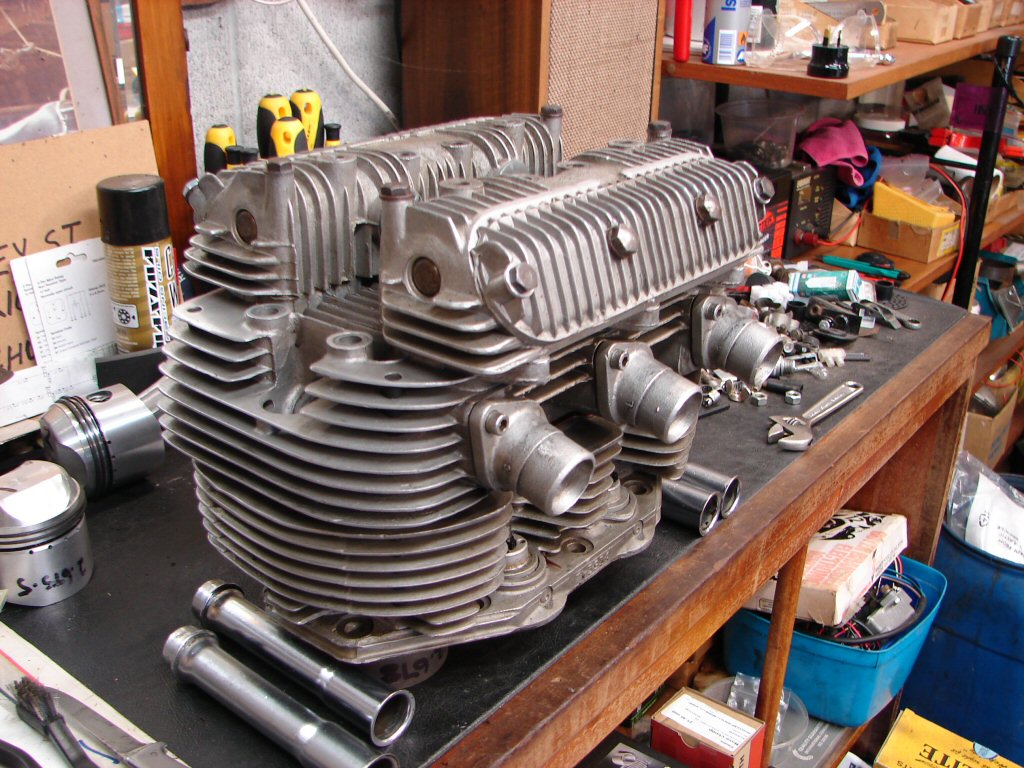
When happy with all that lot enough that final assembly will be free of annoying hiccups, I took the rocker boxes outside and wire brushed all the crud off them. There was also remnants of silicone sealant on the covers and inside the pushrod tube seal recesses which is a solution looking for a problem. The seals are compressed enough in the vertical plane when setup properly, so sealant is generally counter-productive. I reserve it for lightly coating the base and cover gaskets, plus the six allen screws at the leading edges of the rocker boxes whose threads also need a smear.
It was now time to insert the pistons into their bores while it is easiest to do so on the bench. The centre rod was out anyway to check the bearings, so that gets bolted to the crank last and via the sump plate opening - just as it was unbolted to remove.
The outer pistons get parked at the bottom of the liners so that the gudgeon pins can be pushed into the little ends of the rods as the barrels are lowered into place. I had dear beloved lined up to assist, as at least three hands may be required, but as she was absent for the most part of today I did it myself, only because it is a manageable process that can be done slowly and ways of supporting the barrels are easy to arrange. It worked as intended until the final circlip dropped inside the crankcases. Fortunately I was able to fish it out through the sump aperture by using an extendable magnetic probe, so only a few minutes penalty.
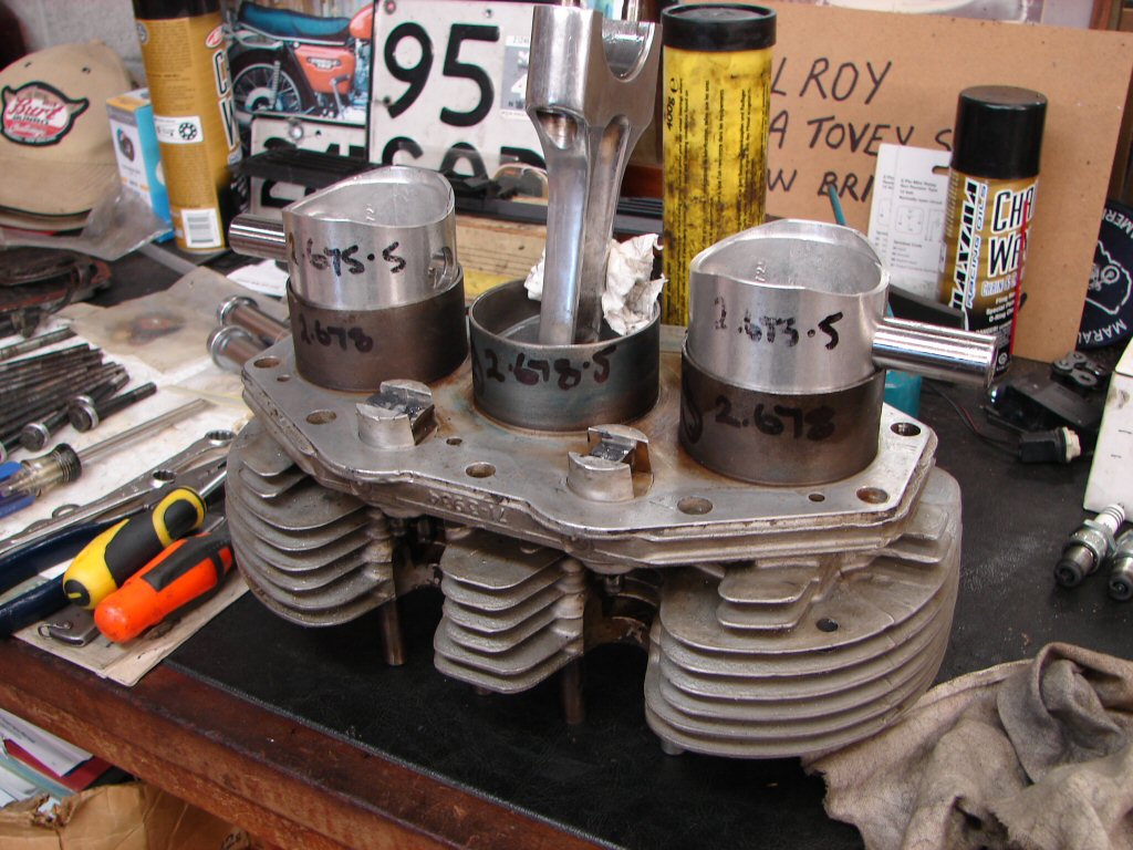
Once again, preparation is an absolute must for these fiddly numbers. The base gasket needs to be greased before starting, and all the cam lobes, gudgeon pins and holes oiled, as are all the camshaft lobes. The cam followers are also sporting a good dab of very sticky assembly lube in the above pic - but it is hard stuff to apply, as it just refuses to let go of the tube, or surface, or finger...
A couple of rubber bands are perfect to ensure the rods will sit dead centre and be easy to line up looking through the extended gudgeon pin, thanks in most part to the perfectly placed pairs of barrel base studs which can now be helpful for a change, instead of just being a bitch to tighten the nuts on...
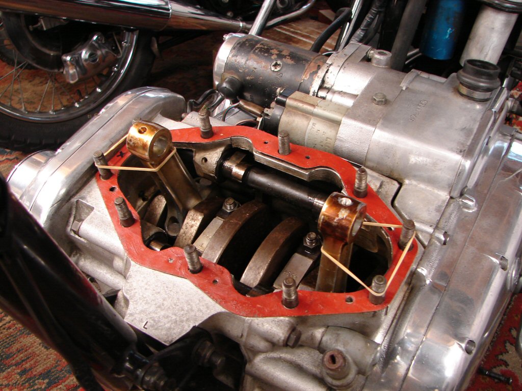
That all got me to having the barrels in place without much bother, although the centre rod can be difficult to convince to slant rearwards to find its crankshaft journal. I shall work on some clever means of guiding that in future, as this method of fitting barrels when using the hideously strong oil ring expanders on the current Hepolite piston rings is almost the only way to do it at all.
I do have another cunning routine that is used if the entire bottom end has been apart, and this method was devised from the same centre rod last approach, but the engine design itself afforded the ability to fit the outer pins part way through the assembly. Just don't forget to fit the inner circlips before you start...
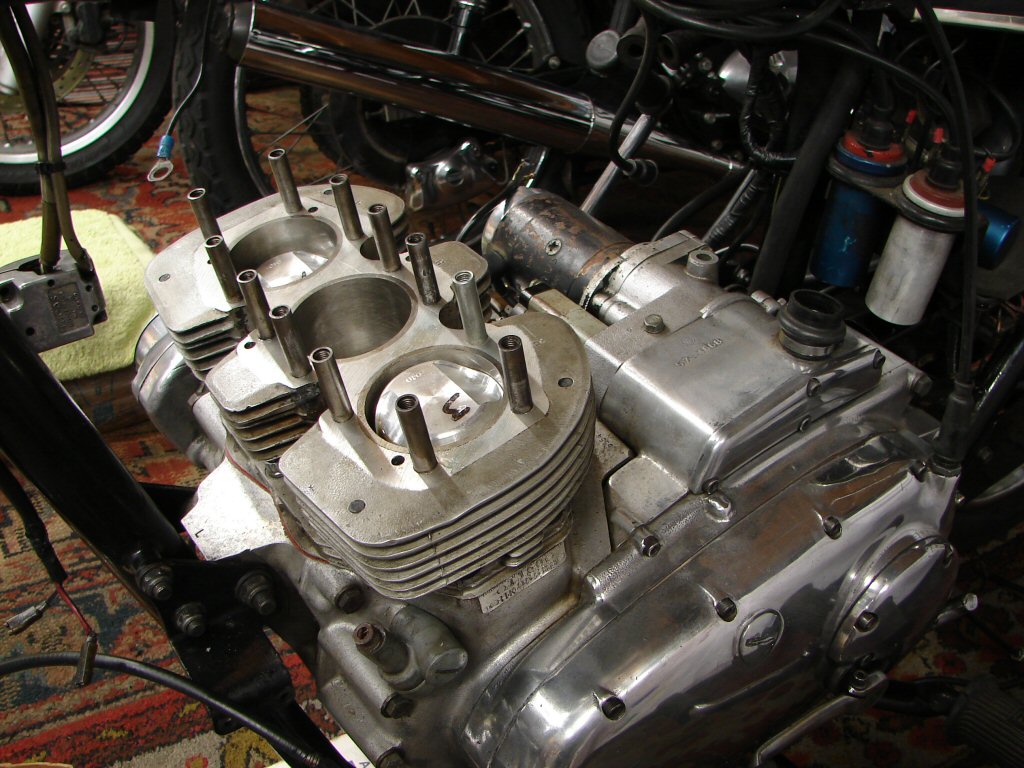
Centre rod is bolted up with its bearing cap well oiled. Barrels are pulled down to a moderate degree, but will be gone over again after an overnight compress. The first job in the morning will be to refit the sump plate with new gaskets and self-locking nuts - there was an odd mix of nuts present that I presume were the last to be in use.
I have had notification that the latest parts order should arrive tomorrow, which means it will be possible to proceed with the cylinder head fitting. A few correct bolts are also amongst this order, so our degree of normality will be steadily improving.
So the first job revealed that my suspicions about the sump plate nuts were well founded. I could not get the new UNF nuts to begin threading onto the small studs, and it turned out that someone with less sympathy for machines than me had forced metric nuts up the threads, so I spent some time running a die nut up all the studs before I could actually bolt the plate and filter into their gasket sandwich.
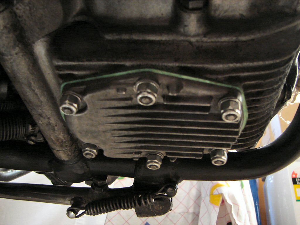
That sort of set the scene for today's progress from the get-go.
I put the head on the bench and unscrewed the allen screws which had been left finger tight in their intended positions. One felt really gritty and a small piece of alloy thread came with it, so I had a good look through them all. Four of the six short threaded holes had already been helicoiled, but this one had succumbed to the nasty modified allen screws and the thread was cactus. The remaining original hole was in good condition so I helicoiled this one straight away.
Removing the inlet stub to keep it safe from emerging drill bits showed that while it had its thermal insulator it was missing its two paper gaskets. The thermal barrier is made of very hard material, so thin gaskets are used on both sides to prevent any air leaks that could otherwise allow air to be drawn directly into the inlet valves, as that can lead to some very nasty outcomes. I am constantly reminded that less skilled mechanics fail to understand why things are fitted where they are for specific reasons, so leaving them out is a recipe for future problems. I believe this was a major contributor to the accusations of poor design or assembly that plagued British bikes over the decades, through no fault of either factory related procedures - but was down to poor service work done by under skilled owners and would-be experts.
So we have this new helicoil and another need for parts in the form of the thin gaskets, of which I may have some but not necessarily all.
Turns out I did have a new set of gaskets so everything on the head is now complete and ready.
Yay.!
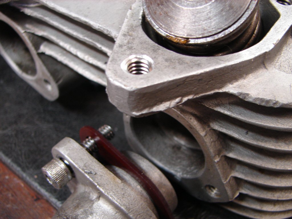
Another rather tedious job which I decided to blot my morning with would be to run a tap down all the pillar studs, and a die nut over all the head bolts, as I have not been privvy to how their relationships may have been, and we want no surprises after the sticky head gasket has just been laid on the block.
One of the studs was brand new and had seen no service yet. Most were otherwise fine, but the actual No.1 stud in the tightening sequence had an internal thread problem, and when I looked at the head bolts I found one with a very visible patch of shiny damaged thread at about the same depth. I ran the tap up and down the internal thread quite a few times with WD40 until it was good enough for a different bolt to move freely down to the depth which would be full travel. The stud did not respond to the same level of attention with the die nut and had to be rejected. Extra friction in a place like the head joint means proper torque is not delivered to the bolt, but defeated by the problem thread, and as the head bolts are only set to around 20ft/lb that can be a serious consideration.
I shall not even attempt to guess what may have caused the problem, but sure enough I found an excellent example in my old bolt collection so we are covered.
That gets us to a place where the head and barrels are ready to be united in marriage, so the rocker boxes got their final quality control and the four inspection caps removed in order to locate the pushrods. The lower seals and cups are in place on the cam follower guides as well as one fibre washer per, which will be adjusted if not enough seal compression is on offer with the current geometry.
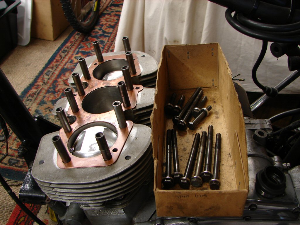
When the head goes on the oil drain dowels will need persuading to go all the way into the block by use of a rubber mallet, and the four outer head bolts will be used to provide a bit of preload until the bolts through the rocker boxes are introduced. Once fully down it can take a bit of levering to lift the head off again and I do not want that to be necessary, hence all the fiddly prep to try and avoid anything counter-productive. After that the rocker boxes will be trial fitted without pushrods in place to measure the amount by which the tube seals will be compressed. All necessary steps in a logical sequence.
Today was going to suffer a series of interruptions so I decided that I would not begin the head fitting. A block of focussed attention is needed when embarking on tasks that require quite a number of processes to follow one another, so I needed something less ambitious to do.
I had cast an eye over the tail light assembly a few times and identified a few missing parts, so had assembled them from old and new sources. They were mostly to do with the actual fitting together of the parts we had, but it turned out that there were a few other issues which only become evident when trying to fit the pieces together.
First a wiring repair was made, then the actual plate the light mounts on was found to be bent and thus got straightened - as did the numberplate mounting brackets. Then the light was fitted up and connected to the wiring, with a missing internal screw and the two sleeve nuts now completing the mix. I also had the two rubber trims which save the alloy housing from interacting with the chrome grabrail.
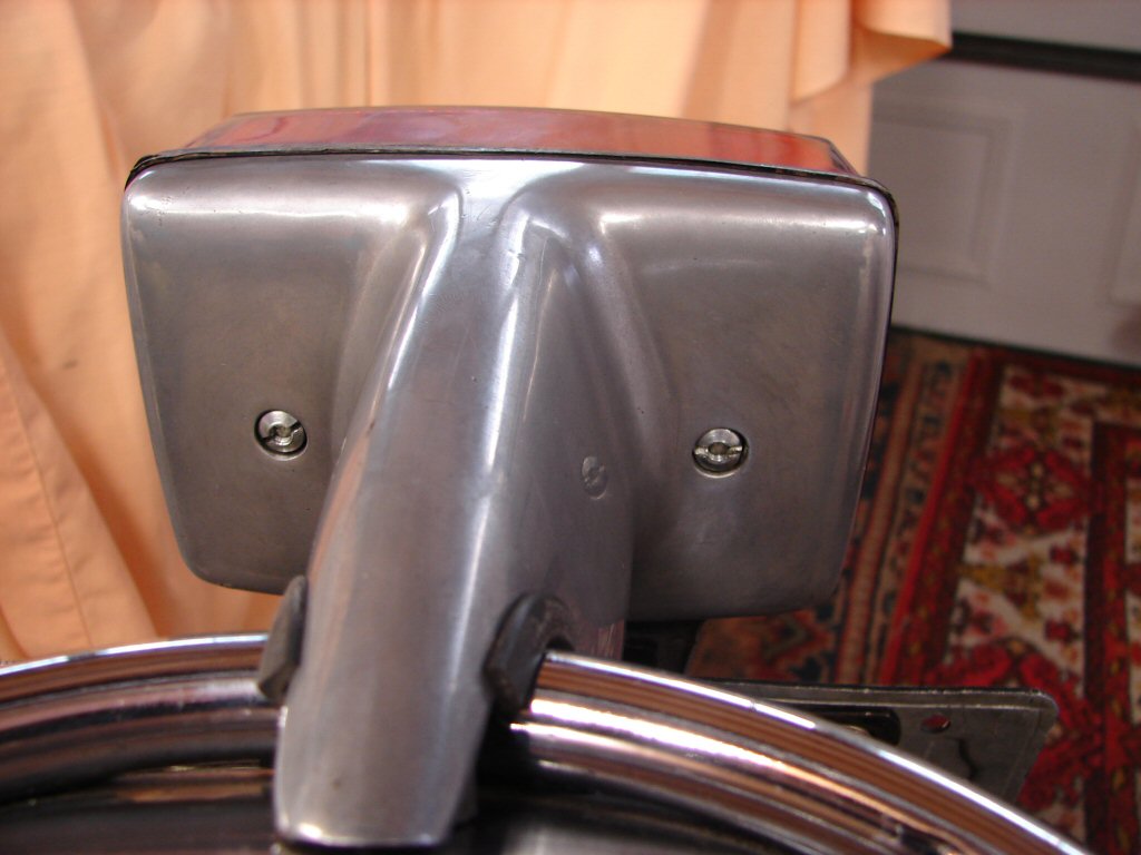
There was also the glaring absence of any indicators fitted to the bike at all, which was going to be a wof issue, so I dragged out the various boxes which contain a good number of old indicator lamps and stems that may yield a good pair to begin with. There were a pair of the required dimensions to mount to the grabrail so I checked their internals were functional and wires long enough to reach their targets, after which they were fitted up.
I am hopeful that the numberplate might still be live for the owners sake, and it has fitted well - being of period age the bracket spacing was made to accept the old black plates. Co-incidentally I brought my T160 in from Australia in late 1979 having owned it two years from new in Queensland, and it was issued a plate with 'HD' being the first two letters. This one got 'HE' so was likely imported around the same time.
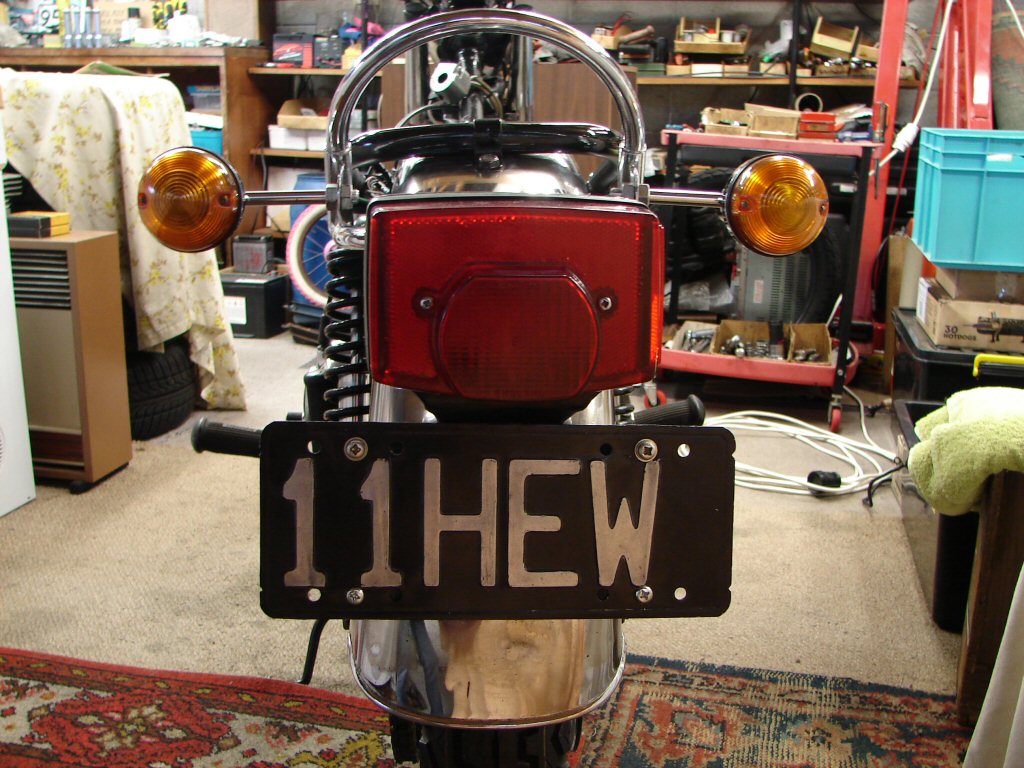
The front indicators were going to provide a few more hurdles as they need long threads to reach through the headlight mounting spacers. I did have a whole set of stems rechromed once, but they made such a poor job of the plating that they were never used.
Now I am trying to find where I put them, and the number of possible locations is stupendous...
I gave up on that and adopted a simpler approach. These are to be functional indicators but not concours winners. The object will be to get the bike road legal and begin the sorting process that all rejuvenations require.
If you have not yet run foul of this - here is a suggestion to short circuit it ahead of time. The repro indicators for a long time had no I.D. on the lenses, and these are all in that camp. If a wof operator should begin the "does not meet legal requirement..." line of BS I always give this reply - "Well, I can go home and swap the lenses off my other bike, come back and get my label, then go home and stick these ones back on, or we can simply know that is what will happen and avoid it. What do you think..."
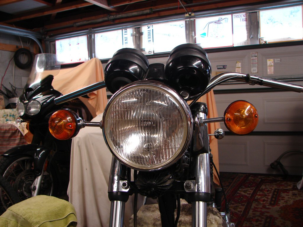
I connected the wiring and attempted to clamp the headlight rim back on. I say 'attempt' because the screw is as tight as a tight thing, and after reaching its limit the rim still fell away afterwards. Using some rather firm persuasion I managed to completely unscrew the retaing clamp to find that it had been previously tightened to such a degree that the clamping bit was bent to a 'U' shape. Crazy stuff. I put it in the vice and coaxed it back to the shape it should be, and then found that the screw action was restored to a very pleasing level and the clamp now works perfectly.
You do ponder these things...
Next we wandered outdoors and applied a coating of copper spray on both sides of the head gasket, gave it a few minutes then parked it in place with consumate ease. The head dropped on and took very little persuading to settle completely down. With the rocker boxes stitting in place I use a touch of clear machine oil on the lower bolt threads as they go in, and give them a moderate tension in the correct sequence. They will remain like this for an hour or so while the copper spray does its curing, then one rocker box will be removed at a time to check the pushrod tube seal compression before adding the pushrods and a smear of sealant on the base gaskets before the final fit.
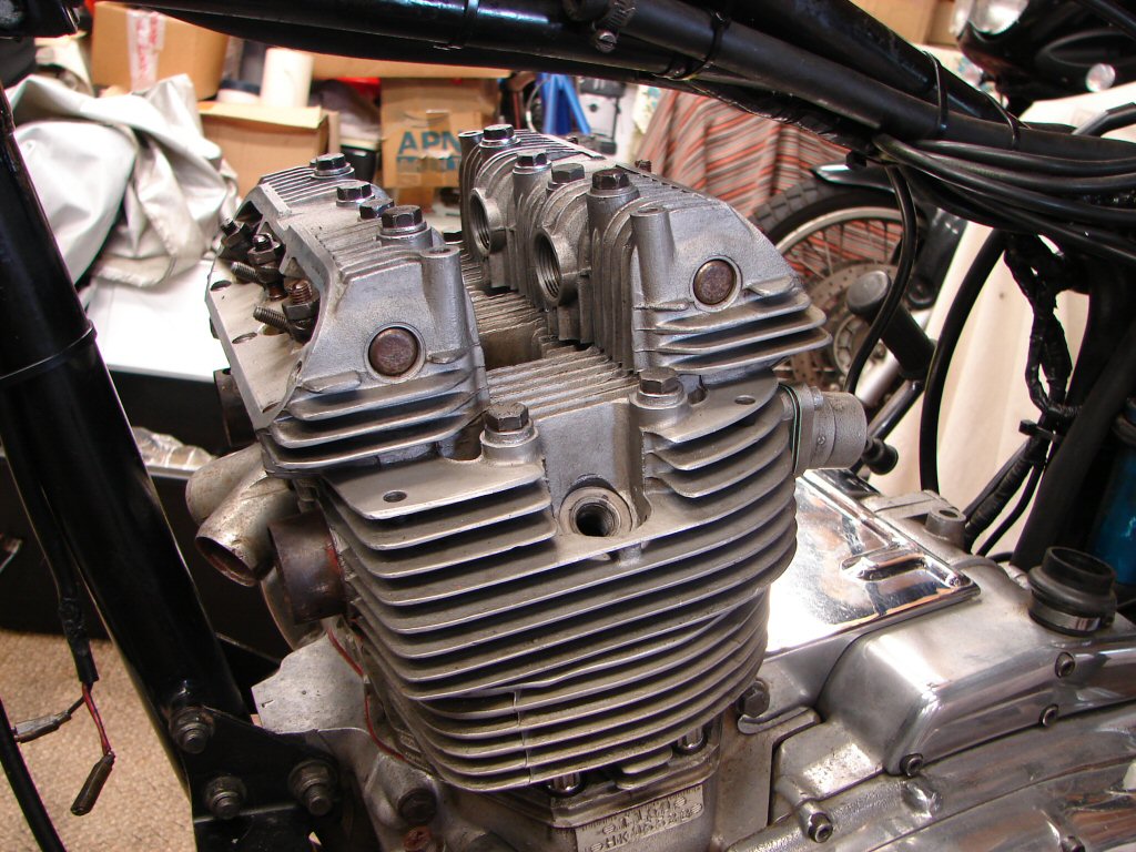
The exhaust rocker box is always my first - for practical reasons. Because the T160 engine slopes well forward, the pushrods fall inside the rocker box when trying to locate them to the rocker arms, and need to be retrieved via the inspection cap hole. Much easier to do this before the inlet rocker box gets assembled, and as the pushrods in the inlet fall forwards into view there is no problem.
I fit pushrod tubes with their upper seals, lower seals, cups and gasket, add the rocker box gasket, then drop the rocker box over the top and add the end bolts just to keep it in the right place. I then use a feeler gauge to measure the gap between the rocker box gasket and the base of the rocker box itself, as this gives the amount of compression that the tube seals are about to experience. I aim for .035" to .040" as enough crush, but today there was a gap more than twice that much.
What the bleedin heck..!
It took little time to realise that sanity had not gone out the window, but a good skim of alloy from the surface of the head certainly has. Not only has this lowered the rocker boxes significantly, but will have upset the valve geometry quite a bit.
The only remedy that I feel can be used is to fit a second head gasket on top of the first - something I have never tried but the best way to restore both the valve geometry and the normal compression ratio, which might otherwise cause pre-ignition issues. Not sure about that but best avoided anyway.
Having taken every possible step to avoid the chance that the head might have to come off again, it looks like the bastard is about to. Three steps back.
Pizzle-rot.!
Oh well - perhaps a few wiring repairs as a form of light relief. Sort of 'tail light' relief at that. It seems that the multi-pin plug that connects the rear harness has had a small conflagration at some point, and several effected wires have been dealt to in an unfortunate fashion. One example is that one of the recently invented indicator lamps features a bullet connector underneath the mudguard, which is hardly going to go the distance.
I decided to tackle the whole arrangement by first removing the tape wrapping, and in doing so discovered that the two wires which connect to a flasher unit when present had been taped into the loom seeing as the entire indicator system had been deemed unnecessary.
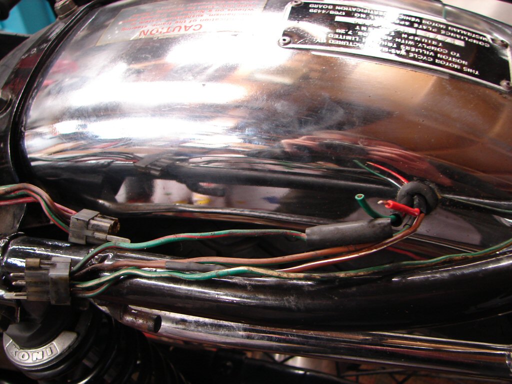
In original guise the left side rear indicator wire runs inside the guard, then exits alongside the rest of the rear harness just south of the plug, so I reinstated that along with some plastic sleeving to protect it from flying rocks and the like. The other indicator mimics this on the right side, but then runs around the frame loop well out of the way of the seat base which can otherwise trap it.
There was a red earth wire which had been removed from the multi plug, presumably because it had been the heat source due to a short circuit in the tail light, but the repair was too short causing all the other wires to bunch up, so that got redone and it seems we may have completed that area of wiring repairs.
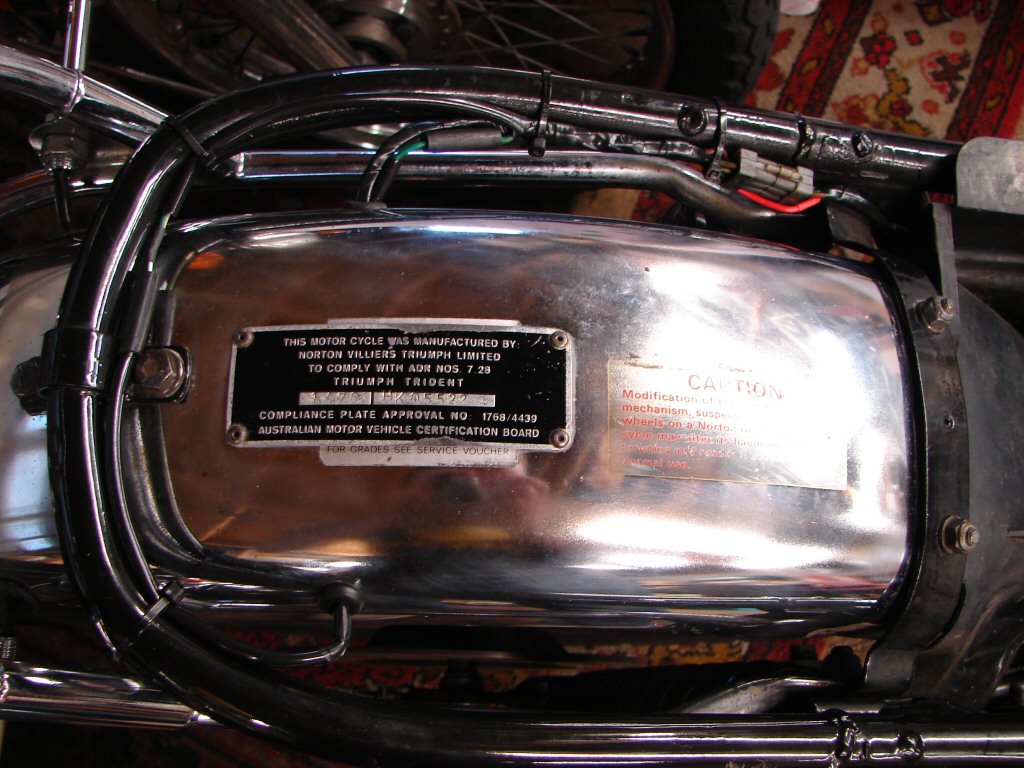
There was another damaged wire further forward which was part of the alternator circuit, and as I was going to be in and under that part of the bike I chose to remove the old Boyer ignition and associated wiring, and install the Trispark. This involves setting the crank with the drive side cylinder at firing position, which is proven by viewing through an aperture on the front of the crankcase, and backed up by the timing mark on the alternator - usually on the 'B' mark, and that proved to be the case.
Until we are able to introduce a battery the timing can not be set accurately enough for running, as there is an LED on the unit under the points cover which is for that exact purpose.
We are however making noticeable visual progress, and I may continue in that vein by refitting the oil tank fairly soon. It plays a part in arranging the wiring as one of the ignition coils lives on it...