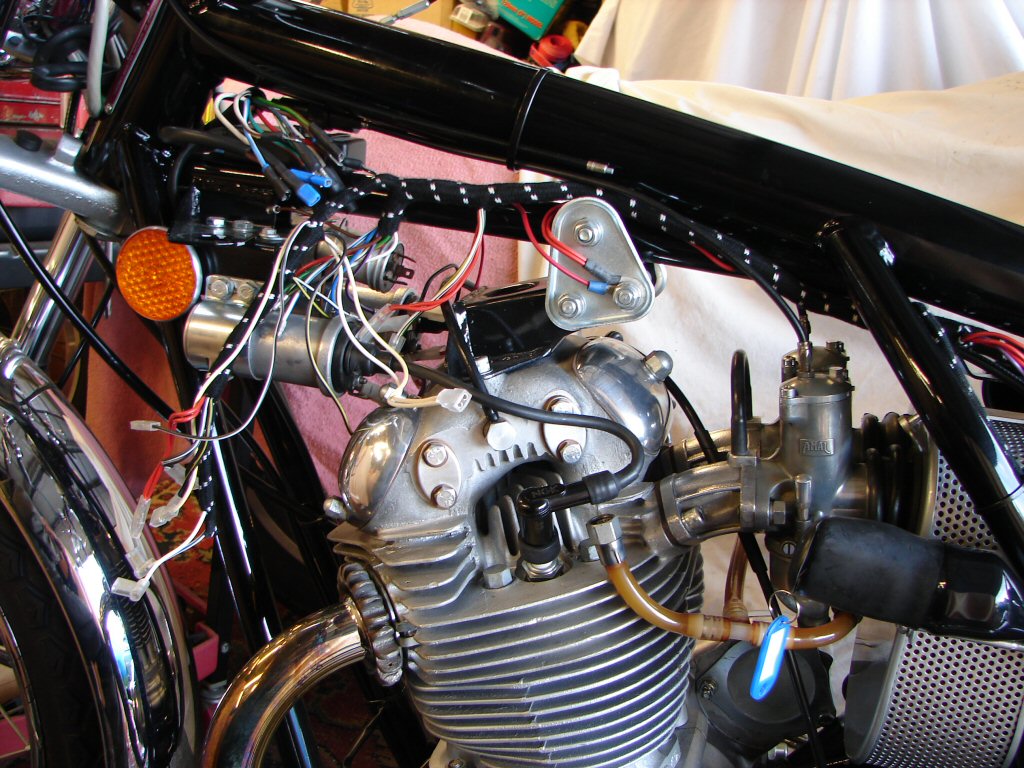
September 2026
1972 Norton Commando 750
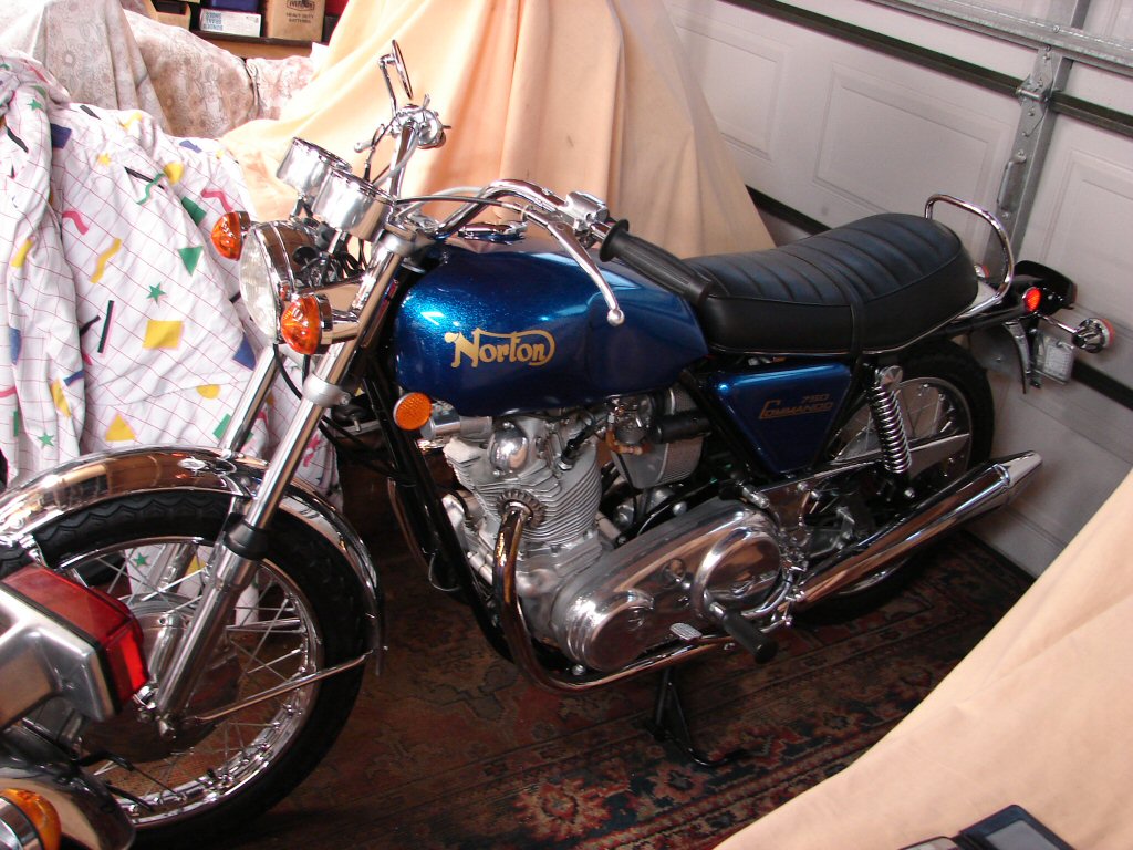
Trouble at Mill...
This wonderfully restored Commando first visited me just over a year ago and had behaved well since. That changed recently and it had been waiting for a space to occupy in my shed to find out why.
The story was that it had been idling at rest when the engine stalled. It was restarted without any obvious problems but after a short time stalled again and smoke began leaking from the wiring loom.
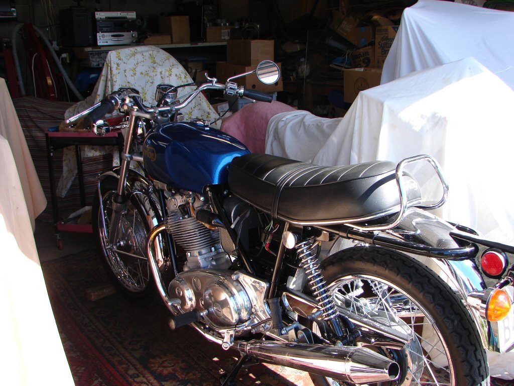
So I found a small area to wedge it into and it was delivered a few days ago.
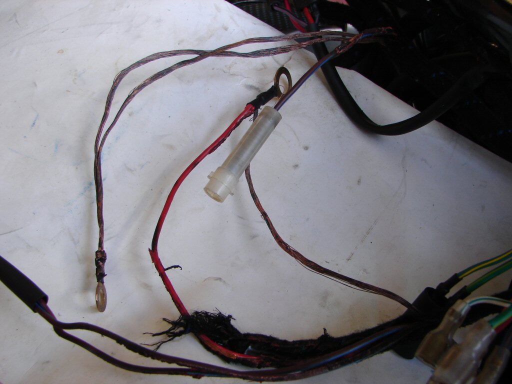
There was ample evidence of a fairly comprehensive meltdown of wiring in close proximity to the battery tray, and a quick check with a meter showed a dead short between the negative and positive wires leading away from the battery connections. It was not difficult to see why, as the two wires were welded together where all the insulation had vanished just downstream of the fuseholder but before they disappeared into the main harness.
I soon found some red wires on the main earth locations which had also melted, so a major short had taken place causing the wires to get expremely hot - but they were all earth wires and not feeds. Besides that, the fuse had not failed and nor were the wires in and out of the fuseholder showing signs of distress. Not until the covering was removed where the battery wires headed towards the main harness did I find that all insulation had gone and the two opposite polarity wires were stuck together.
This bike had been fitted with a solid state rectifier/regulator at some stage of its life, and that was mounted just to the rear of the left top shock mount, but all the wiring associated with it looked to be above board. Then I found burn marks on a sub-harness which used to head down to where the original zener diode would have been on the right side footrest mounting. The earth wires were still connected there and were also looking deprived of smoke.
I fished them out and they are the wires appearing from lower right in the pic, with one earth wire devoid of insulation but what would have been the 'live' wire spade terminal well covered at the end but melted together to the bare earth further up.
Hmmm.
The only way a dead short can fail to clear the fuse is if the source of the short has been from another connection to the battery. I could not see any obvious or obscure reason for this to be the case.
Due to the fact that the engine had been running when this all took place means that the alternator would have been producing power, and the reg/rect would have been passing all the current the alternator could produce, so I decided to check both of those items to see if they appeared to be damaged or ok. There is no point in beginning wiring repairs until the source of the problem has been identified, if only because the wiring damage may extend beyond what is already obvious
The good news at this point was that the only area effected seemed limited to the charging circuit, and a quick look inside the headlight confirmed that everything else was fine.
So I removed the reg/rect and tracked down the method for testing it.
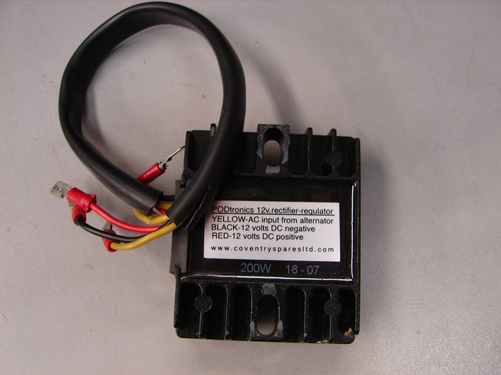
The Podtronic unit is well trusted and does not appear high on the list of failure prone types. The only tests that can be made on the bench are to check the viability of the diodes which produce DC from the alternator AC, which is what 'rectifier' means.
This unit gives every indication of being fit and healthy, although the regulating side of things can only be checked in a running situation. I feel pretty sure that it will be ok if only for the reason that all its associated wiring is unaffected.
Next port of call would be the alternator which could have been given a good fright.
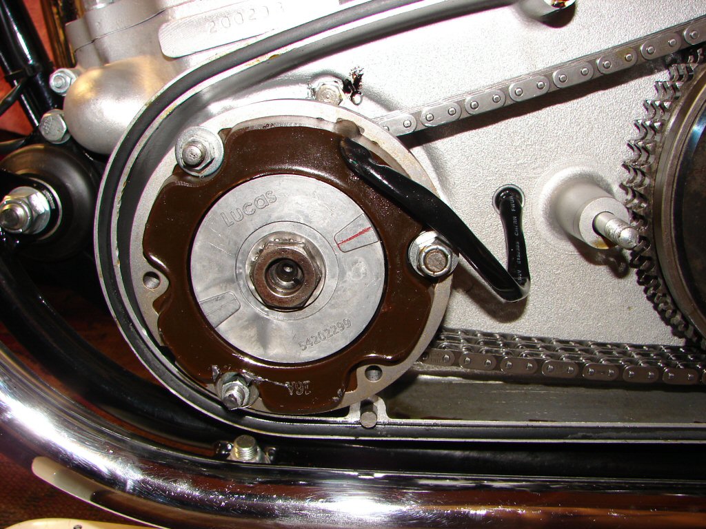
Fortunately the Commando alternator is easy to access, and besides checking out fine on a meter it appears to be in good condition and probably was a new unit from the time of the restoration process.
Having now viewed the most likely suspects and being of the opinion that they were certainly not implicated in what went down - despite being exposed to it - I was fast running out of ideas as to what the hell caused the meltdown.
So what you do at such times is you just sit and look at it all. There has to be an explanation, and it is a very necessary one.
And there it was - or actually wasn't. Wait a minute, where is the rest of the fuseholder.?
Ah yes - now I remember that the owner had given me another piece of the jigsaw - it was a small charging lead which also gets attached to the battery - and it was still sitting on the bench with the battery, which I had given a cursory glance and checked the voltage of as being ok.
I would now need to give that lead the ninth degree...
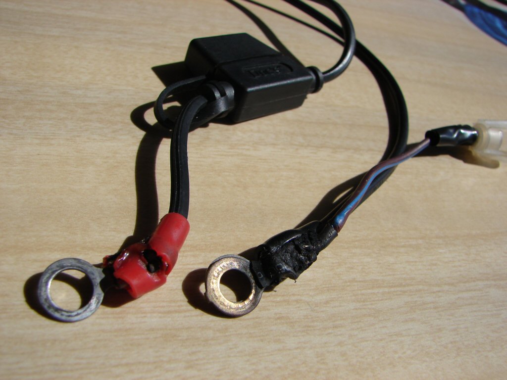
The most obvious thing was that the earth terminal had suffered a lot of heat, which was only to be expected as the wiring harness earth lead terminal would have been bolted on top or underneath it, but neither of the two black wires going away to the charging plug gave any indication of being heat damaged. Nor they should.
Likewise the short piece of wire going to the fuseholder looks to be in good condition, but wait...
If - as I am happy I have established - no fault current went through the fuseholder, why does the heat shrink over the terminal joint look so melted.? That sure looks like it has been exposed to more heat than would be required to shrink the sleeving.
And there it is.
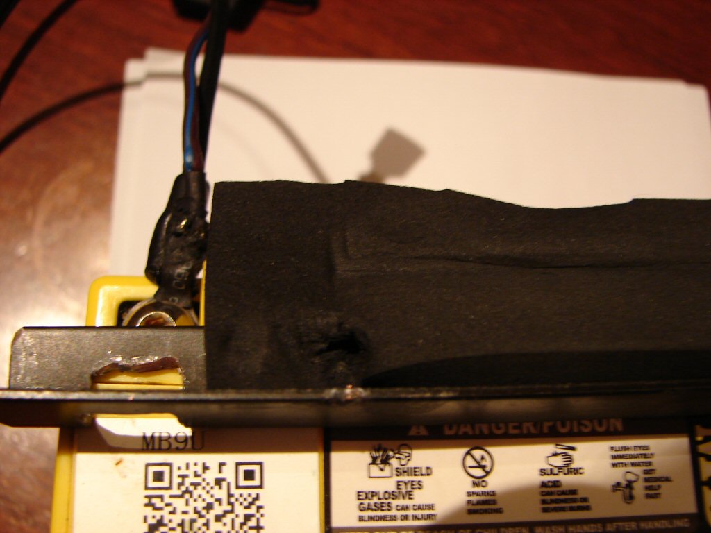
It is no more visible to the naked eye than it is to the camera, but there has been some direct contact to the top of the terminal body, most probably to a piece of earthed metal. If so, that would explain everything rather neatly as to why mostly only earth wires would be melted - other than wiring that was running next to them in the loom - and the obvious culprit would have to be the metal bracket which clamps along the top front edge of the battery.
As it happens, the bracket used on this bike has steel rods which anchor it to steel eyes at the base of the battery - so it is missing the safety feature of the original which used rubber straps as the fastening material.
I dragged all the bits indoors tonight to make the final forensics, and it seems we have indeed found the needle in the haystack. As I happened to have a pair of the original straps amongst my stock you can easily see that the rods were a trap waiting to be sprung..
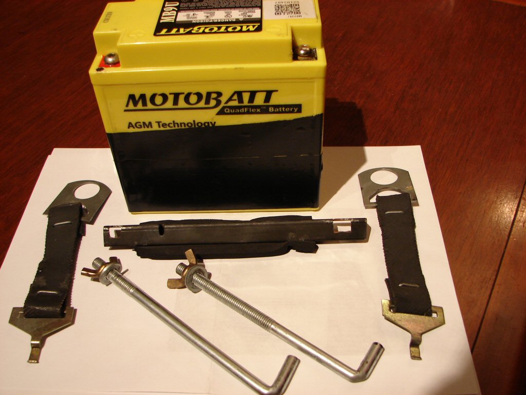
You can actually see the signs of electrical damage on the leading edge of the bracket on the right side, and it had taken place right through the thick rubber padding whose job was to ensure this would not happen. I am thinking that this problem might not have occurred with a different type of battery, as the placement of the terminals is quite high and there will have been some pressure between all the offending parts all of the time, so this was always going to happen, it was only a matter of when.
It would also appear that this might not have been the first time contact had taken place, but this time it was maintained long enough to cause the meltdown. The occasional misfire can always be dismissed as something random.
Despite the poor lighting the following photo clearly shows the points of contact on the top of the terminal and the edge of the bracket, with signs of recent spot welding. There is a large hole around the area through the rubber which appears likely to have been heat related melting.
It will not be too hard to grind away a small section of the bracket to create adequate clearance between it and the terminals in future.
Now that there is no doubt in my mind as to what the cause was, the work will get a bit laborious involving stripping the fabric off the harness to expose the damaged wires and replace them. As the tail light sub-harness will need to be released in order to extract the main harness from under the frame tube there is going to be a fair bit of time involved just to get enough access.
I sure as hell am not up for fitting a new $314 wiring harness seeing that mostly only earth wires are involved, and as is my custom, the replacement wires will be slightly heavier sized copper cored which makes them more robust and better at doing what is required.
Although I cannot entirely rule out any other incidental damage as yet uncovered, I am very happy to have everything making sense and certainly able to be made better than it was to begin with. The areas of the harness which will lose their fabric covering are well out of sight so being taped instead will not offend too many purists.. lol.
On with the show.
Well - I underestimated the degree of difficulty trying to open up a melted wiring loom that has fabric covering. It is bad enough just with plastic covering - but possible.
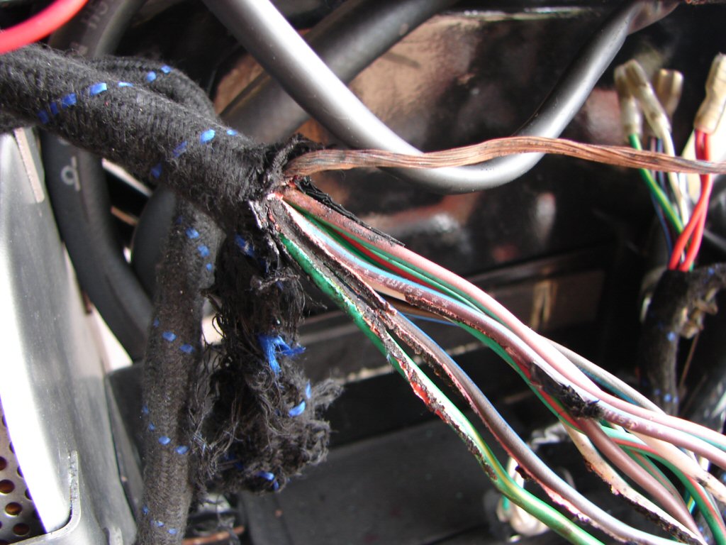
This fabric covered loom also has a plastic covering beneath the fabric, so we have melted wires which melted plastic covering into the fabric. It is only possible to chew half an inch off at a time while trying to free the good wires from the bad. To make matters worse, there was still a solid earth on the right footpeg mount despite the zener being long out of service, so the damage went in both directions with the zener earth being the worst.
They are the ones on top of the rear frame tube, and those earths are still used by various accessories.
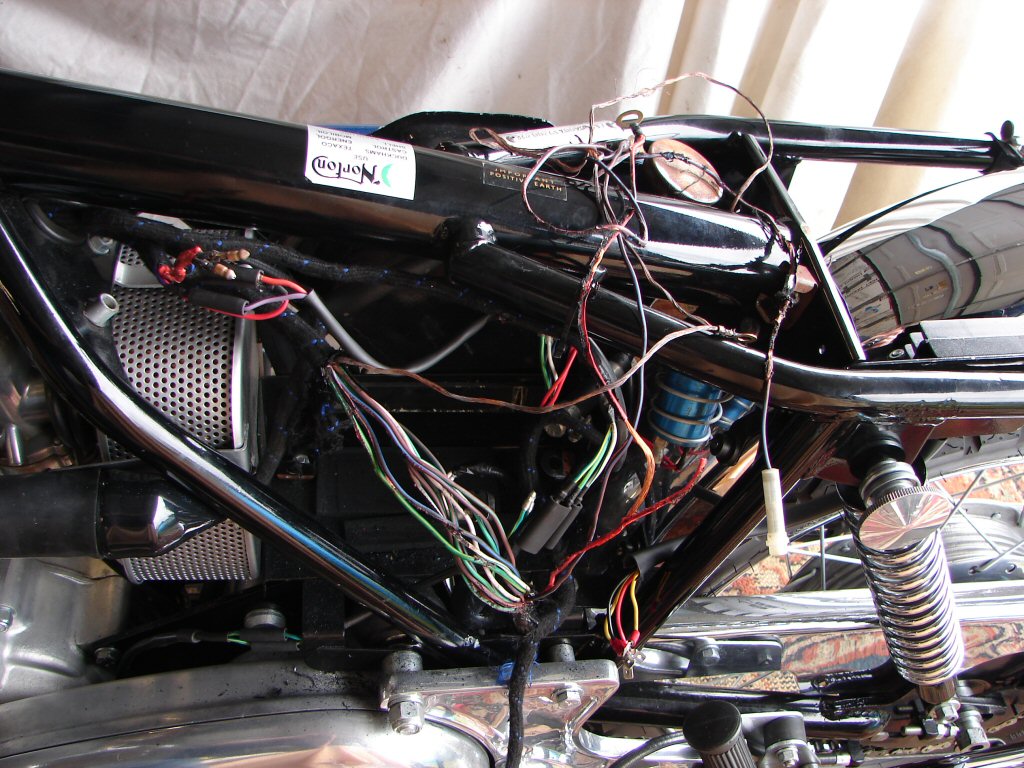
It was quite difficult to extract the loom from under the frame, but there was no other way to begin working my way forwards. Pulling the melted sections apart was doing more damage to the semi-healthy wiring as can be seen below.
Wires which were still 'live' when the earths melted through them caused visible burnt areas which would also need to be repaired - possibly by cutting the bad bits out and soldering new bits inbetween.
One thing was for sure - the entire loom would have to come out of the bike to effect any good quality repair if it proved to be even viable. Considering the time factor versus the reliability of the end result I had to reverse my thinking on a replacement harness as being the cheaper and far more desirable option overall.
I hate having to change direction on a repair, but you can't know until you know.
I was also aware of another potential issue which had come to my notice. My preferred suppliers had two looms of this part number left in stock, but restocking has become a hit-and-miss affair as more parts are no longer attractive to produce. Better to change direction now while we have the choice - than later when we don't...
Now - all I have to do is straighten this loom out to look like the diagram...
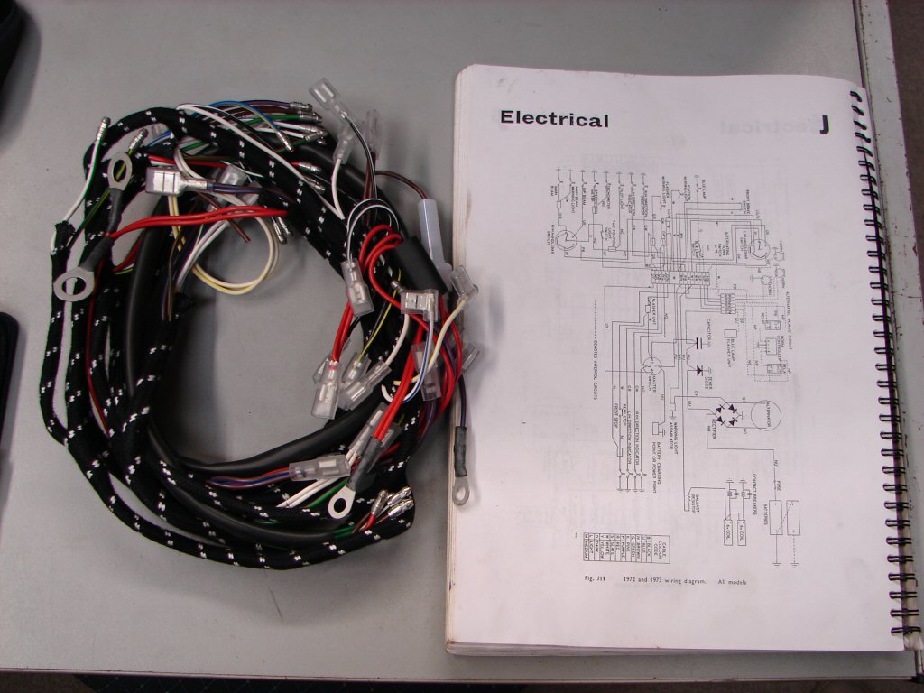
The battle begins. The new loom gets fitted beginning at the rear, working its way forward. The old loom serves to show where everything spreads out and in what directions, then is disconnected as we move along.
My personal brief is to make a tidier job than the last one, despite the fact that many original wires are no longer used due to items like electronic ignition and regulator/rectifier having been added to the mix somewhere down the track.
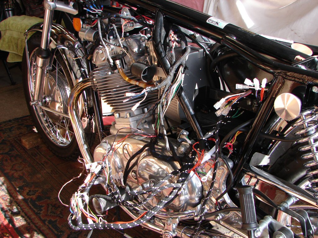
For no reason I can think of, when the last wiring loom was fitted - I presume during the restoration - nearly all of the bullet connectors were chopped off where the main loom joins the headlight loom underneath the fuel tank. As it will be easier to adopt the modified situation rather than reinstate the original, I will have to chop all the bullets off the new loom and fit whatever connectors are required to match up.
Having gotten to the point where the old loom could be completely removed it was time to make a list of which colours connect to what as I pull them apart.
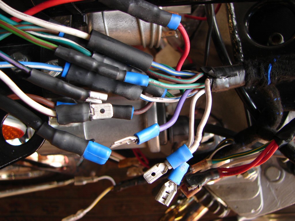
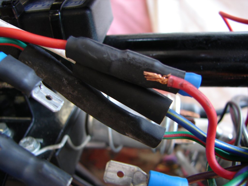
Most of the replacement connectors that were used here are the "crimp-through-insulation" types which I do not use. One of the first things I was taught as an electrical apprentice in 1967 was that every connection of a wire must include folding it double before making the connection. It was an immediate 'fail' in a practical test if this was not done. These crimp through terminals do not have an internal bore big enough to take a folded wire - therefore they frequently pull out given any encouragement at all.
Like this one just did..
So I only use non-insulted terminals which easily accommodate a generously folded wire. The insulator is then pushed over the completed terminal from along the wire. They last as long as the bullet connectors in service but are much easier to interfere with when needed. They just take up a little more space.
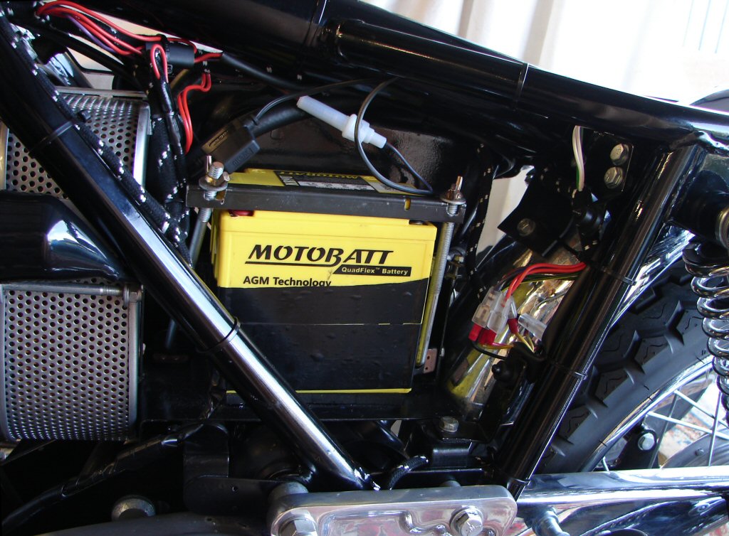
With the tail light loom connected, horn and rectifier connected, flasher unit and rear brake light switch etc, I trial fitted the battery to see what measures were needed to prevent any risk of battery shorts in future.
Having been perusing the Norton workshop manual there was a picture showing the battery in place and the wiring attached to the battery terminals at the rear. Obviously the factory fitted battery had the terminals placed where they needed to be for that to work.
However, our Motobatt job has terminals mirrored on both sides, so the obvious cure is to put the wires on at the back where the bracketry can never reach them. And it works.
At close of play today we have reached the forward union of the two looms, so things will start to look pretty well complete once that is done. Then there will be a whole lot of testing to be done to make sure that everything still works as intended.
Tonight I will be checking my Pazon wiring diagrams to see where it is supposed to get its power supply from. As the wiring of ignition coils is a part of the Pazon installation there will be a number of potential feeds to supply it, but I want to use the best one.
One of the grittiest jobs today was refitting the ignition switch, as it is mounted in a place where there is not much room for the wiring to reach it, and it put up quite a fight before being coaxed to behave. Here it sits innocently like nothing ever happened..