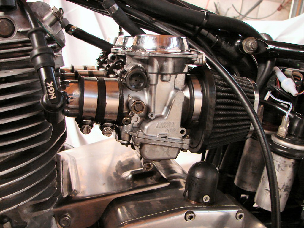
April 2026
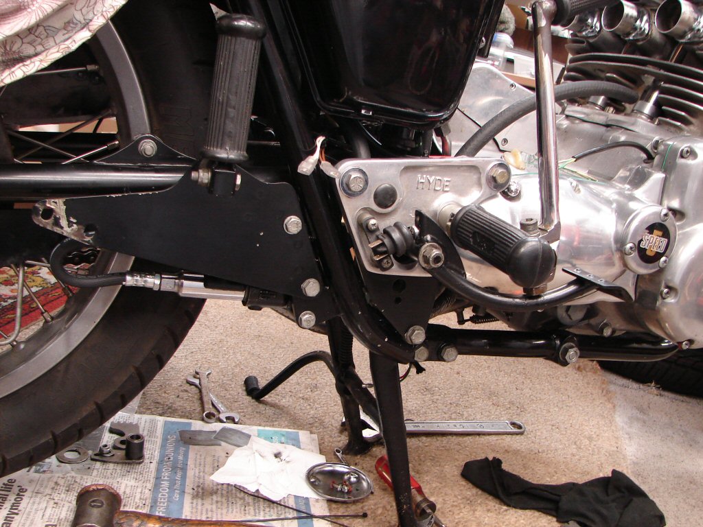
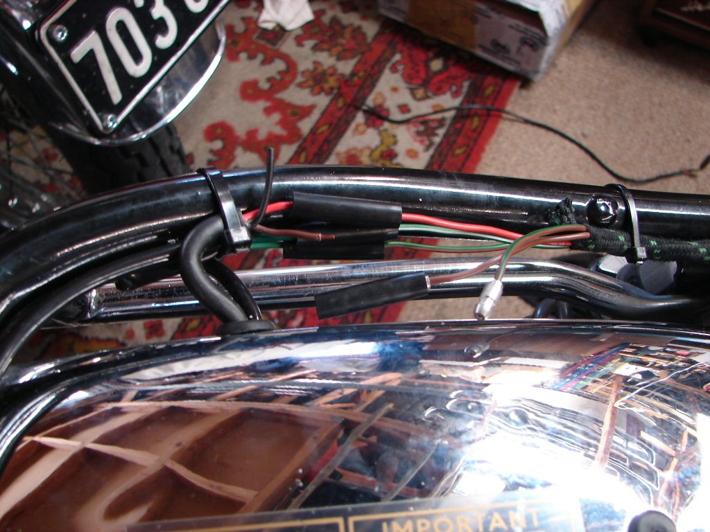
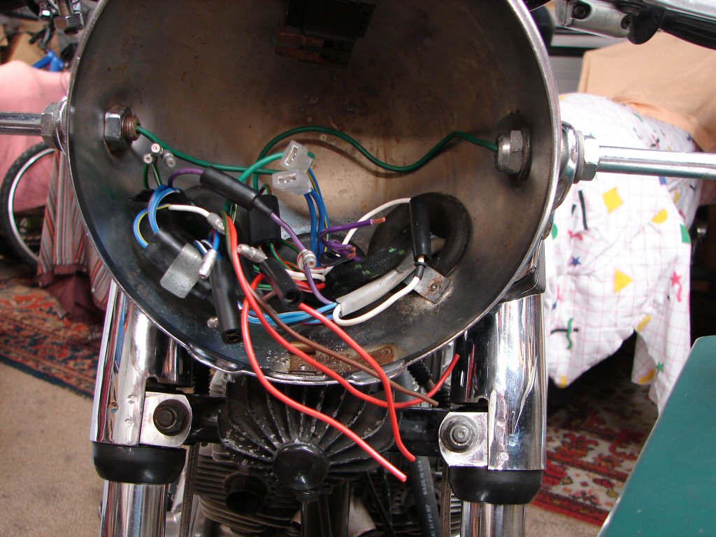
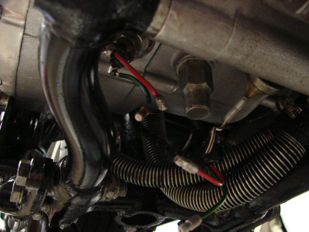
It can be seen that the wires for the brake light switch are not long enough to reach it, nor would they have reached the original, so I shall need to make up a pair of extended wires to make that work. Otherwise the wiring is gradually assuming its place amongst the general scheme of things as progress dictates.
Next I chose to complete the cylinder head assembly, most of which was only to adjust the valve clearances. When in the first stages of this I fit the six allen screws along the front edges of the rocker boxes without their alloy washers. These are then fitted before the covers go on after valves are set.
To my mild annoyance the very last screw decided to strip its thread as the tension reached what is needed to squash the washers out and seal potential oil leaks. Luckily though, it was the last one, as that can be helicoiled without removing the cylinder head.
Phew.!
Here we are tapping the thread for the helicoil, having used a few smaller drill bits to clean the old thread out then reach tapping size, and I placed a small screwdriver in the near thread to give me a guide for keeping the tap perpendicular. You can handle doing this in one plane, but not two at right angles simultaneously. I got her indoors to be my eyes and keep me parallel to the screwdriver until things were far enough underway that it would continue thus, while I concentrated on keeping it vertical.
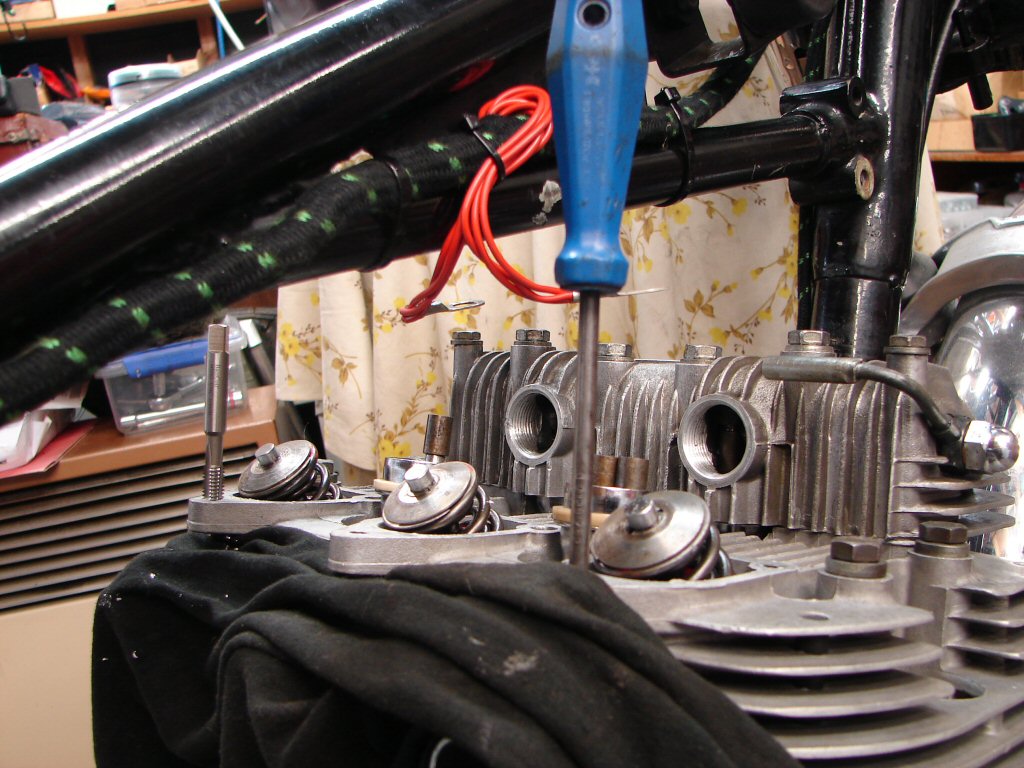
It worked perfectly, so after cleaning the alloy rocker box gasket and applying new silicone sealant the rocker box went back on. Then all the head bolts got torqued in the correct sequence again and I adjusted all the valves, refitted the round inspection caps, then fitted the covers with their new gaskets. I do not use any sealant on the first fit, and wait until the engine has run to decide if they need any or not. If not I then give them a smear of grease so they will come off again when needed without ripping.
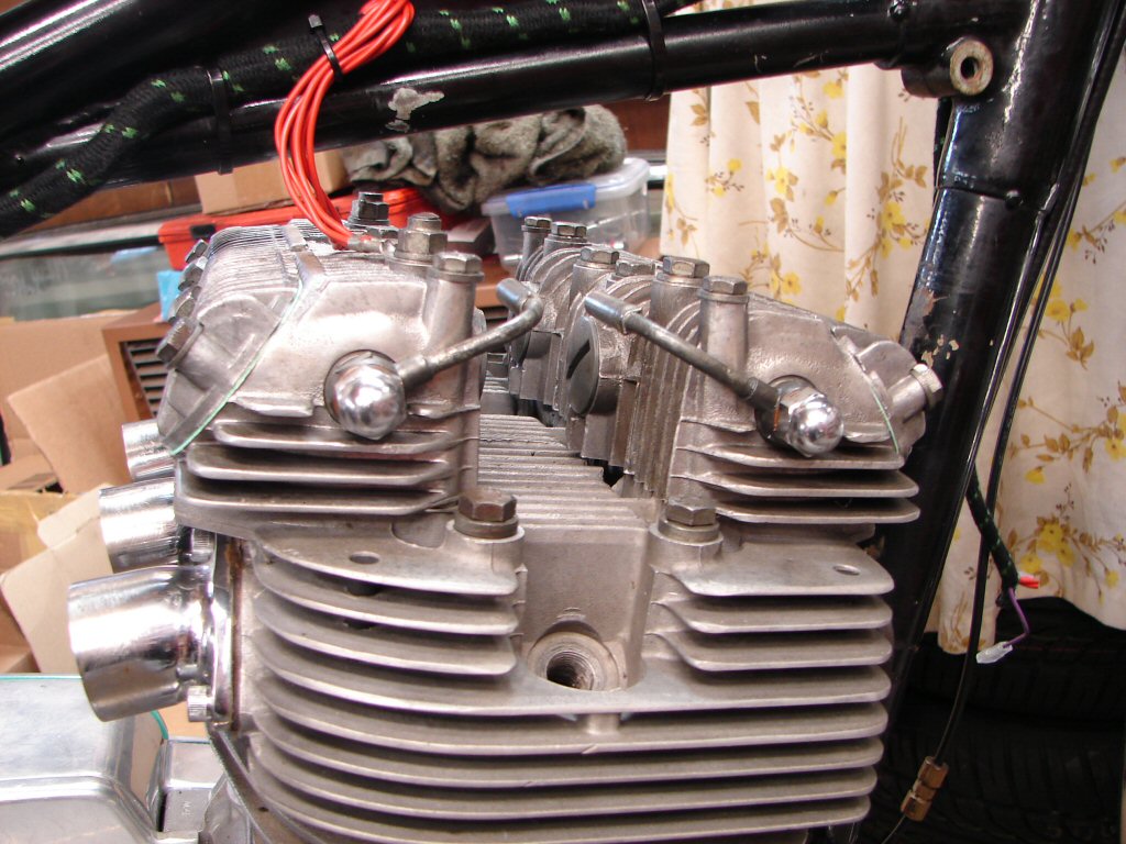
The rocker oil feed pipes were then trial fitted with their original copper washers, as I will need them to be in place when the oil lines join the mix. The two small lines that carry the oil into these pipes are shagged and will need replacing. When that is all getting its final fit I will also add the new copper washers that were included in the gasket set.
As the new length of oil line arrived today I began the hideous job of attaching the feed and scavenge lines replete with their respective protective springs to the two pipes which exit beneath the crankcase and between the lower frame tubes. There is bugger all manoeuvring space down there so everything has to be managed carefully and has to want to fit before it will. Happily it did, and I am now at the point where the lower clamps are fully tightened, but the last job will be to add a sturdy cable tie behind the clamps as an insurance that neither hose will be able to slide off unless they both do at the same time. I figure the chances of that are as slim as anyone could make them.
I had been pondering how I would be able to flush the oil cooler to ensure that no sparkly bits would enter the oil tank again. This needs to be done in the reverse direction to normal flow, as the internals of the cooler are quite restricted, and it would be counter-productive to risk forcing any crap further into the cooler rather than out of it. The oil lines are too neat a fit to make swapping them end for end, then doing what I do with every oil change. After draining the tank and primary, I refill them both with new oil. The scavenge line is then disconnected from the top of the oil tank and placed in an ice cream container. The engine is then started and the remainder of the old oil from the crankcase sump and the cooler is bled off while it is still quite warm.
And there you have it - of course.!
I will fit this cooler to another bike's scavenge line when I am changing its oil, and bleed two coolers for the price of one.! Only about 2 litres of oil will be wasted, where one usually is anyway. Bonus is - the oil will still be hot, and there is no shortage of pumping pressure available from the triple oil pump. I have two T160s that would benefit from an oil change right now, but I will use the one with the cheapie Castrol GTX rather than blow a few litres of expensive synthetic away... lol.
Today I began by completing the oil feed line at the tank and adding my cable tie to the two lines under the engine. The return line is also in place and the wiring loom is getting pegged as it finds its best places to be. Mostly done by copying my from-new T160 which still has all its wiring where the factory put it. In the photo the alternator wires can also be seen to have been extended, as have those for the rear brake light switch.
While the soldering kit is out I will also attend to the neutral light switch which has no wires at all attached to it, but I shall solder a pair on. The oil light switch has been connected, but I have yet to put a meter on it to make sure it works.
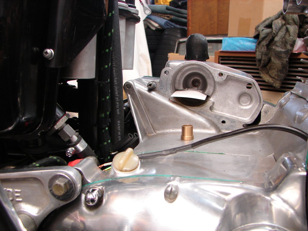
I then thought I would fit the new starter motor unit as it also has wiring which needs to be added to the plot while things are still accessible. That got me to the "spot the deliberate error" section. The shaft on the new starter is larger than the original Lucas one so it will not fit into the resident bush, one being imperial and the other metric. I pretty soon rejected the idea of pulling various cases off again and figured I should be able to open the bush up the required amount by careful drilling - hence the shaped business card in place to avoid swarf going into the clutch housing.
I had already digested all the fitting instructions that came with the starter and there had been no mention of the bush dimensions, nor is there any hint of what the starter is being fitted to - it reads like a "standard replacement" scenario. I had another poke in the box it came in and found a bag of mounting screws, along with a new bush, slightly more substantial but seemingly of the same O.D. as the original. Well, at least I will not have to be super careful with the drilling, as I will just be removing the old one rather than resizing it. The difference between the two bush I.D.s is only about 1/32", but this means the wall thickness of the new one is even less than the old one, and as can probably be seen was bugger all to begin with. I shall find a suitable drift to aid the fitting, and will also use a flame to warm the alloy housing first.
Oh well, things were obviously going too smoothly...
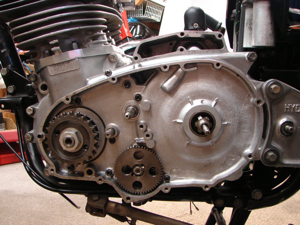
Meanwhile the oil pump is nearly ready to do its thing with some oil. There are enough hoses in place that any surplus oil can be taken care of easily enough, although I must remember to reconnect the oil pressure gauge or things could get a bit slippery. If I fit the rocker box feeds and blank the cooler hose some new oil will be forced into the rocker arms which will do them good, especially during the first start.
I have been trial fitting the left side rearsets so that I can plan the order of assembly proper. It is more compliant than t'other side as it is well spaced out from the engine mounting plate and there is enough space to work between the two. The only potential snag is to remember to insert the long bolt that secures the actual footpeg, as it is too long to be fitted after the Hyde mounting plate goes on. It would be advantageous to have a working gearlever in the near future, so that is the catalyst.
The drilling of the old starter bush began with the first bit I had that was bigger than the old shaft had been. I kept drilling while increasing the drill size by 1/64" each time, which allowed a controllable process. After drilling I measured each bit and compared it to the new shaft size. I got to the point where I knew that the next bit was going to give slight clearance, and after drilling I cleaned up and trial fitted the starter.
It glided into place even though it had refused on the previous size bit, so the clearance must now be less than 1/64", and I could not detect any lateral play at all. The bush still has even thickness walls right around, and will in fact now be the same dimensions as the new bush. I have decided to leave it in place, and the new bush can be a spare part for future use if in fact it is ever needed at all. The original bush in my clutch housing looks and performs as good as new, which figures as it is only under load for seconds per start.
I am allowing the bush to soak in oil overnight, and will grease the shaft before refitting the unit tomorrow.
It looks more compact than the Lucas, but promises to deliver more.
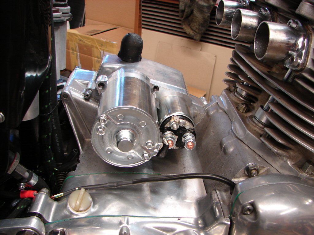
The starter got fitted after a final check of everything, and the job of wiring it began. There were a number of slight changes in wiring during T160 production, but as we are starting from scratch we should not be effected by that, more by the fact that this is not a factory starter unit.
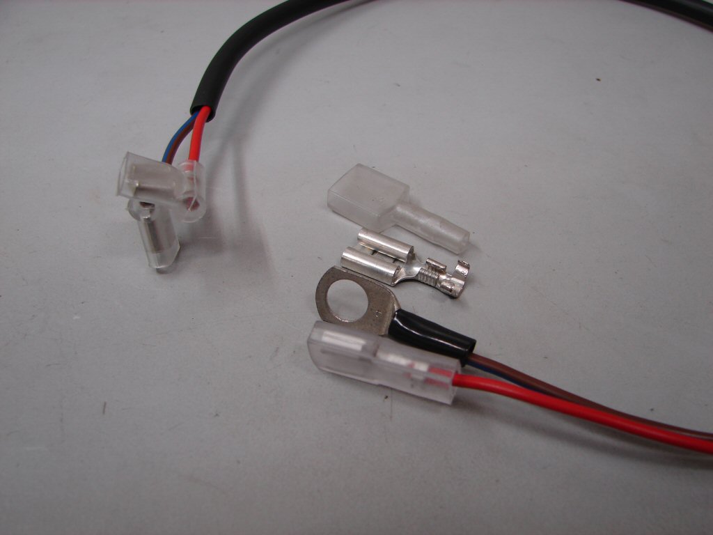
The first problem was that the sub harness which connects the relay to the solenoid had the wrong connector on it where it picks up battery voltage at the solenoid. I was able to pry the offending terminal off and fit a lug which will fit the solenoid ok. Somewhat more concerning to an electrical guy is the fact that the two wires in this sub harness are less than half the cross section of the factory items. Hopefully the new starter might be a bit less hungry with its solenoid current.
Second annoyance today is totally related to non-standard bikes. The amount of wasted time involved in making things fit together that were never made to fit togather means that every deviation from a stock bike extends the time/labour content to a point of exasperation when so much time gets spent going backwards rather than forwards.
Obviously we are not going to all rebuild our bikes on a regular basis, but even maintenance can become a problem when your bike suddenly meeds the non-standard part which is now unavailable, because there are not going to be enough orders to warrant producing another batch.
I figure that my Hyde 830 uses mostly standard engine parts, but I have already had to have a part made as there were no suitable parts already in existence that would do the job.
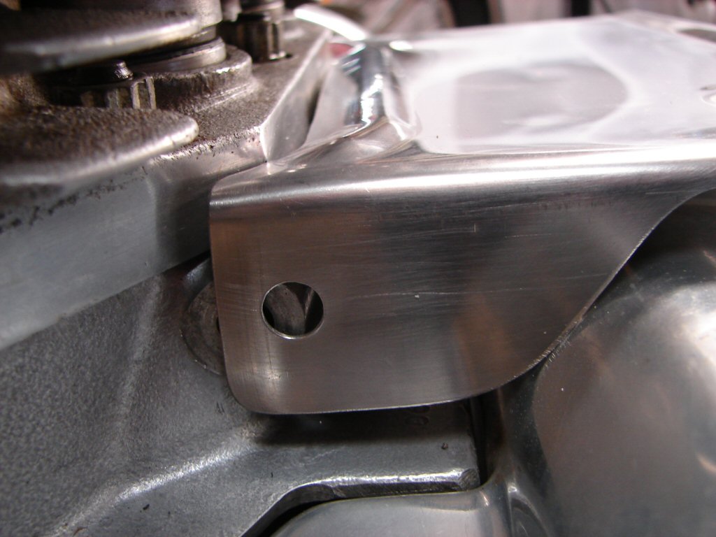
The problem here is that the rather expensive starter cover - a very necessary part if you wish to avoid fuel fed electrical fires - was never intended to work with a 1000cc Hyde cylinder block. The base of the block extends further than a stock item, so the required clearance for the leading edge of the cover no longer exists.
I used a hacksaw to carefully create some more clearance just where that corner in the barrel base contacts the cover, but it is still not enough to allow the bolt hole to line up. There needs to be a sliver of the entire front edge removed, and I am not set up for much in the way of metalwork, so I may have to resort to a bench grinder for any serious result. I would rather be progressing with engine work whose success is pretty much guaranteed, but things have to move forward in unison or they begin to introduce complications simply due to access problems. The wiring work will become more difficult once the cover goes on, but it has to as the alternator lead passes through the side of the cover, and I cannot solder the bullet connectors on until the lead is through its grommet.
'Tis a trying time..
Now - I know that it takes me much longer to do detail jobs such as this, but I already know in my mind what it has to look like when its done, so I just have to keep going until I achieve that result. I probably spend a third of the total work time on any bike trial fitting and mucking about with things that don't fit to my satisfaction, and I do not charge that time to the owner, because I am not really working on their bike - I am working on it like it was mine.
Is that obsessive - of course it is - but I need to be happier with the final product than the owner is, or I couldn't really do this at all. For many years I would not, because I could see worse problems on the bike than the one I was being asked to fix, and I couldn't see the point. the whole thing is only ever going to be as good as the worst bit. Once people started saying "well if you think it needs doing - do it.." then I finally could. So every part of every bike has been looked at and or tested, in the limited mileage that I test them over, because the bit you didn't look at is the bit that has the imminent problem.
I like to imagine that there were people like me who worked at the factory in the early days, but once management turned into bean counters that whole philosophy could no longer survive.
So - after that mini-rant - I got the result I needed to get, that being it looks better than it did before I started, and even fits.
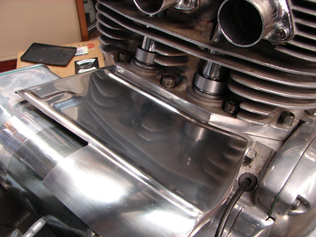
I had to remove about 1/16" right across the front edge and reshape the tapers at both sides, plus the bottom corner in the above photo had to be given a larger radius as it fouled on the crankcase. I looked at another T160 here and that corner was bent outwards for that very same reason.
I have a suspicion that all - or at least some - of the original covers had a thin spacer welded to the inside edge of the bolt hole in order to create a bit of clearance. I will put a washer in there if space allows, and glue it to the inside of the cover.
So there was space and I did fit the washer.
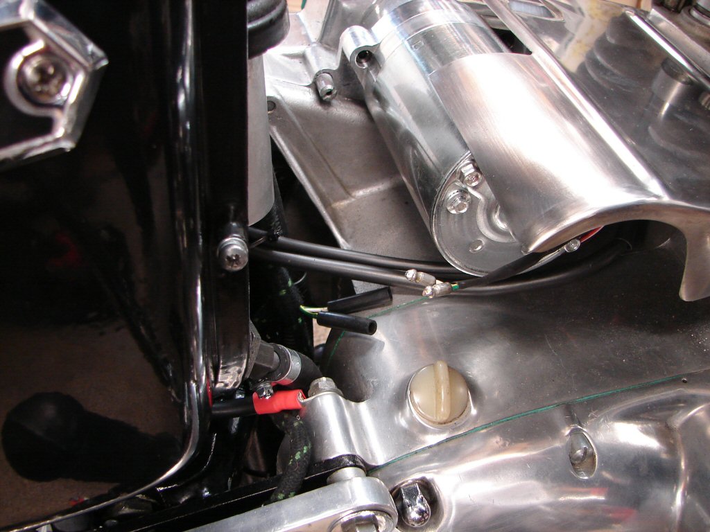
There is a piece of rubber which prevents the electric start from interacting with the top of the starter motor, and while that is on its way I cannot complete the installation, so I turned my attention to some other electrical stuff.
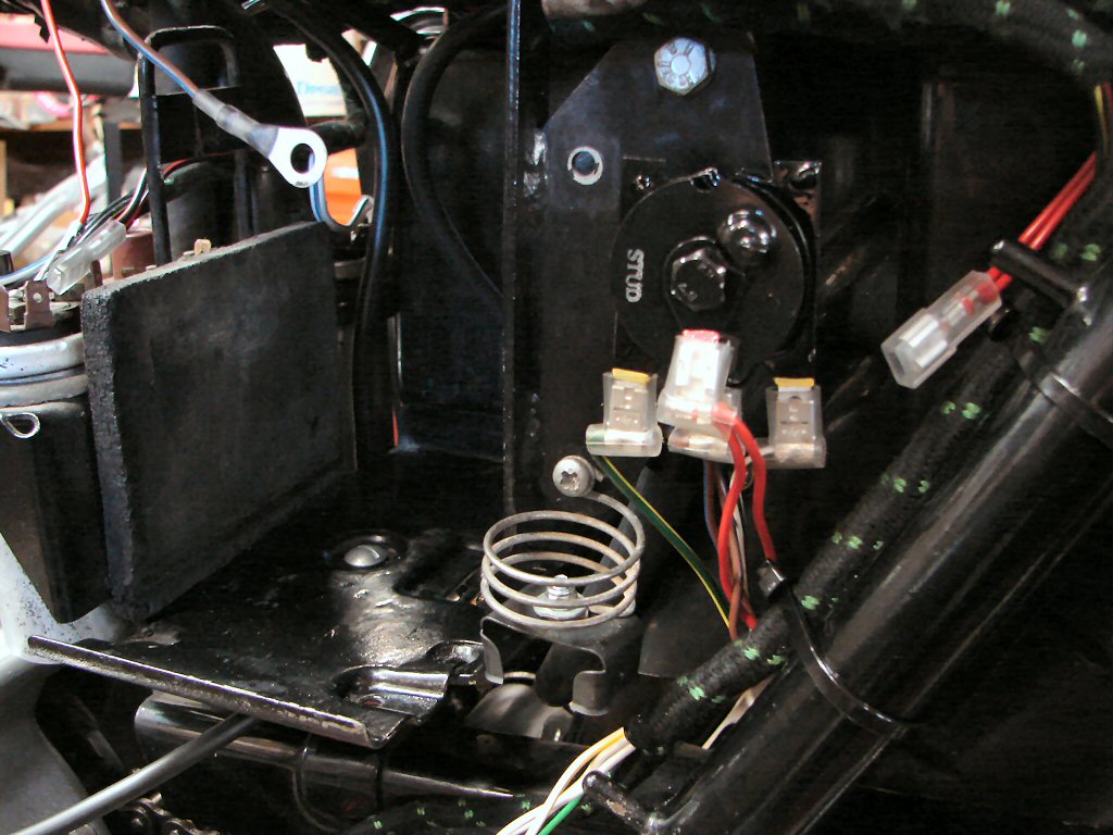
There is a ballast resistor needed as the coils are 6 volt, and that has been mounted beneath the battery tray. The new rectifier is where it belongs and has been connected. The flasher unit mounting is in place and I have a relay to mount where the condensers used to be, whose purpose is to provide the power for the Trispark ignition direct from the battery rather than going all the way up to the ignition switch and back, and through numerous connections which can cause voltage loss. The ignition switch will then only turn on the relay which is a tiny amount of current, leaving the harness free to do other things like power headlights better. The main purpose of the relay is to ensure that the electronic ignition gets as much voltage as possible while the starter motor is in use, because that sucks most of what the battery has, and some ignition systems fail to operate below a certain supply voltage.
As the relay makes an audible click when the ignition is turned on and off it makes a helpful faultfinder in the hopefully unlikely vent of power loss.
As I was unable to proceed further with that I attacked the tail light and rear indicator wiring. The indicator wires were rather vulnerable where they hang in midair so they got sleeved, some new rubber grommets and the wires extended with correct colour wire to meet the harness where it terminates against the rear subframe.
As the wires from the tail light were odd colours I had to pull the light apart to see who did what, and found that the wires at the lamp were in the correct colours - just not inbetween. That made sorting the connections much easier than reinventing the wheel, and will make any future work easier as the factory wiring diagram and the bike now agree.
I ran out of solder bullet connectors at this point, but they are coming with the starter rubber, so should be here today. I also bought some more of both single and double push-in connectors, as there are a zillion wires in the headlight that are going to need them. These old Lucas connectors do their job very well for many years, so they are a firm favourite with me, but like other bits are becoming harder to source. A major Auto Electrical outfit in Christchurch used to stock all these parts, but understandably have dropped them as demand has wound down over the years. We are most fortunate to have NZ bike parts suppliers who have filled the breach and even continue to add to their stock when available.
I next used the delay to trial fit the oil cooler in place, and immediately found that it was caught between the mounting and the exhaust rocker box cover. Of course. The block is taller with a stroked carnk, so whatever minimum clearance used to be there for the cooler has vanished. I looked at the mountings to see if I could create any improvement, because the soft alloy cooler will eventually wear away with engine vibes and they are hard to find replacements for.
The only possible relief I could see would be to drill the mounting bracket holes out from 5/16" to 3/8" so the brackets will move up a little around the bolt that holds them to the frame. Unfortunately one of the special bolts which holds the brackets to the clamps that wrap around the cooler had a nut that would neither tighten or undo, so I had to hacksaw through both nut and bolt to get the bugger out.
Figures..
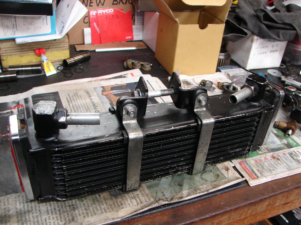
So after a decent struggle, here is the cooler with its mounting brackets bored out enough that it can move 1/16" higher in the frame. Its not much, but enough to stop the contact taking place. I guess it will be necessary to remove the cooler from its mounts in order to check exhaust valve clearances, as it must have been before, but we should only need to do that once between here and the finished article.
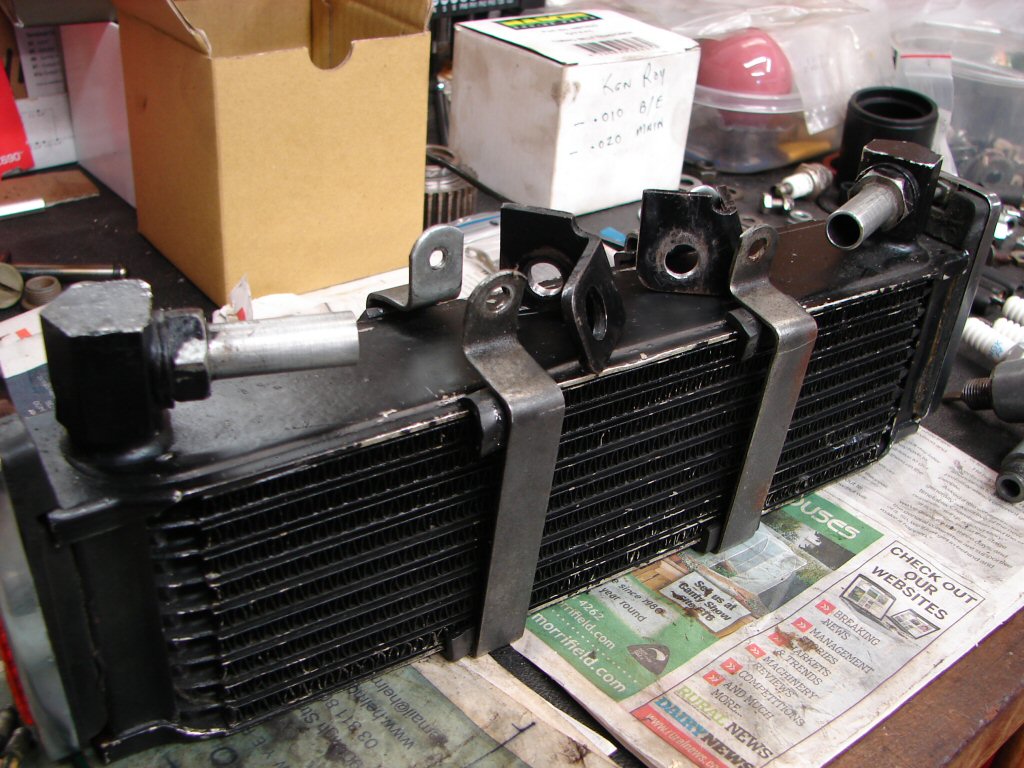
There are special shouldered bolts which hold the brackets to the clamps, so that the bolts can not be overtightened and destroy the rubber mounts. Unfortunately only one bolt was the proper item and that was the one I had to hacksaw off, so a new pair will be fitted.
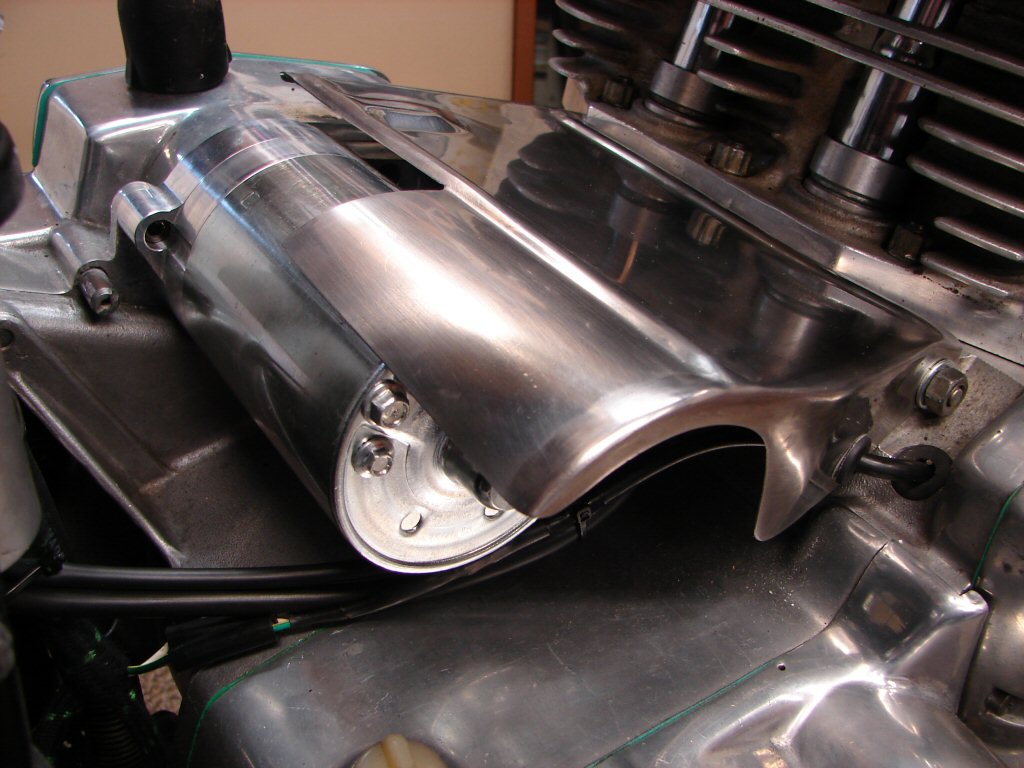
Meanwhile, the parts arrived today that enabled finishing the starter cover assembly, which now has its rubber insulator and the alternator leads are finally connected. The wiring underneath is complete but still has to be finished at the relay end. The cover looks a bit strange with a shorter motor lurking underneath, but that is a sign of the progress that has occurred in 50 years in the design of starter motors. Its lighter too...
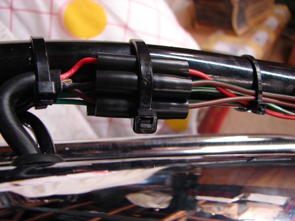
Today's parts arrival also provided the missing connectors to complete the rear lights and indicators. I appreciate how compact the multi-pin plug was that the factory originally fitted, compared to the 5 bullet connectors. They are still available, but as the new loom had bullets already in place we shall not waste time and money restoring that feature.
At least this means that the bike is fully complete from here back now, so some things have gotten off the to-do list.
Continuing in the electrical vein I began sorting the headlight contents. The total lack of a right side switch assembly means that there will be a bit less clutter inside here compared to a stock bike, but I intend to find a pushbutton if possible for use near the throttle. I had considered using the headlight flasher button as a starter button, but then I found that the wiring was all in place for the flasher to work as intended so was having second thoughts.
What clinched it was thinking was that using horns and flashing headlights are uncommon and sudden events. It would be rather counter-productive to find that you had just operated the starter by mistake, especially at speed, so I reckon we need to put a button on the other side near the throttle to make it more intuitive.
It can be seen that the blue and blue-yellow wires with spade terminals are never going to reach the switch in the top of the headlight shell. This has been a recurring issue with the new loom, and I will need to add a couple of short extenders to make it happen. Their measurements seem to have been a bit flawed.
Next will be a bit of soldering on the indicator switch wires so they can mate with the loom on the other side of the headlight. The new bullets will only accommodate rather small wires, so I shall recover a few of the original soldered items which can be re-used and will allow the bigger wires we have to fit properly.
I replaced the two rocker feed oil lines so that I would be able to pump some oil as soon as I had reattached the oil pressure gauge. This also gave me the opportunity to replace the copper sealing washers which reside either side of the feed banjos and beneath the domed chrome nuts. They will leak if given any excuse, so they are tightened up quite thoroughly.
When it came to the oil pressure gauge I discovered we had a fail. The nature of the fittings with these gauges is that they compress as the final nut is tightened and bite into the rigid plastic fluid line. Unfortunately the line has been cut or snapped off the fitting and there is no way to re-use it. I have had a difficult job finding such fittings in the past and have had to import them from L P Williams in the UK. However, I shall try the local people who repair automotive instruments and see if they can come up with something.
Meantime I attached my oil pressure gauge instead, as I do need to measure the oil pressure from the first start.
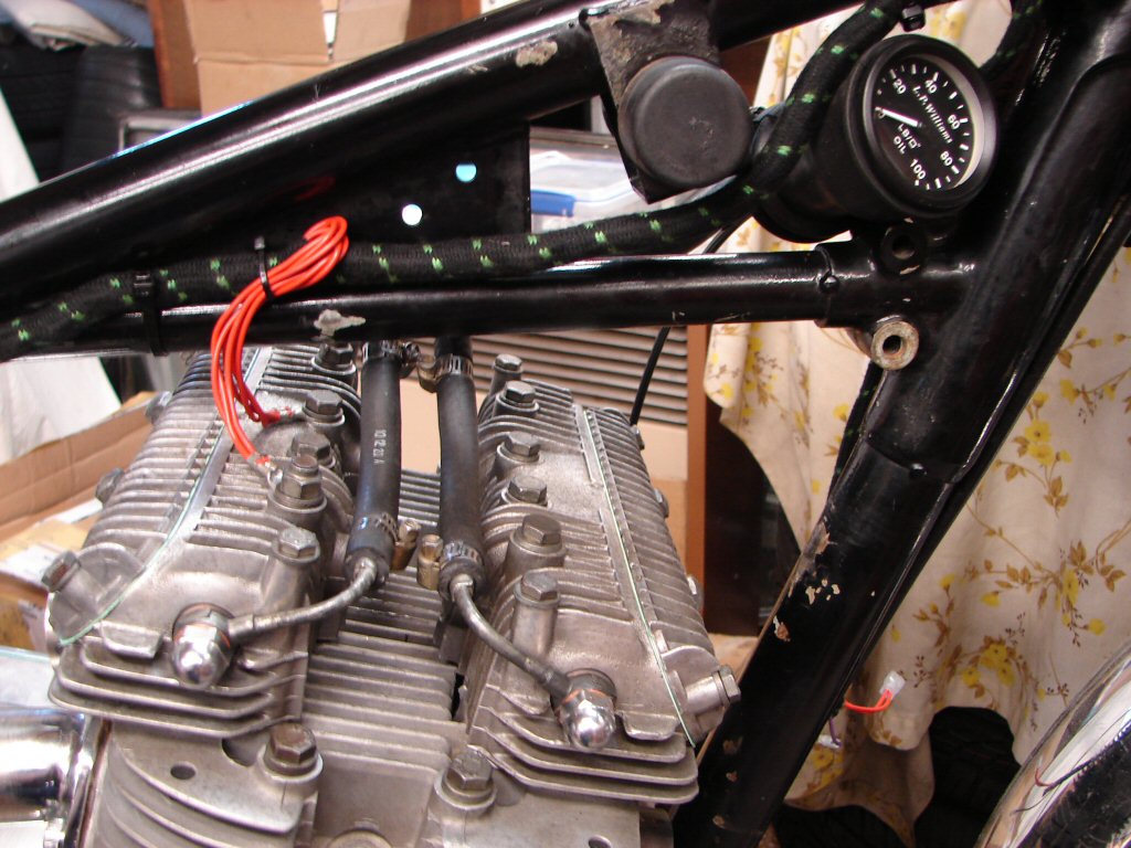
In better news, I could now add oil to the tank and bleed the system. First the pump is wound around with the oil filter cavity cap removed, and this flushes the first section after the pump. The filter now goes in and gets buttoned up and the pumping continues. Just as I began to feel back pressure begin to build on the pump gear I heard it sucking the last of the oil from the tank, so I added another litre.
The pressure now began to build up immediately and my gauge registered 40psi - pretty good considering I was winding the gear at only about 60RPM. I then checked underneath with my meter, and sure enough the oil light switch had switched off. I could hear oil escaping the crankshaft bearings under the pressure, and I kept going until oil began to fist appear at the end of the return line where it would normally connect to the oil cooler. We now have a totally primed system, and a little into the rockers as well. When I test the electric start oil will also flow right through the cooler, which will push more into the rockers, so nothing is left to chance.
Some engines suffer their most dramatic accelerated wear during their first start, so it is well worth the effort, plus it serves as a timely alert if anything leaks.
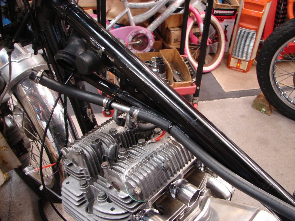
From there I went to the oil cooler for its completion of bracketry. Both the clamps which fit around the cooler were fitted back to front, which makes it a bit harder to fit the bolt that mounts it to the frame, while also putting the nuts out in the front wheel spray causing them to rust in fairly quick time. So they got reversed and all the rubber mounts squared up. I probably should wire the reflectors on as well, as the glue that holds them on is well past its best-by date, and they disappear in an instant. This job is a bit less fiddly if done when the cooler is in place, so I will not panic at this point.
The cooler is now ready to receive its reverse oil flushing, for which I need a few gubbings set up outside so that everything is ready to go the moment I return on the donor bike and we thus get the added benefit of very hot oil.
We also need a fine day - not as guaranteed in late summer as you might think...
As the oil priming is complete it was time to assemble the primary drive, and to begin that I unpacked the cush drive from its carton and got it on the bench. I was pleased to note that the oil seal in the retaining nut had been fitted the correct way round during the last assmebly, and loctite had also been used within it. Both vital steps. The fact that a reasonable amount of oil had in fact made its way inside the clutch would suggest that the oil seal was no longer doing its job.
It seemed to me that this assembly had come in for attention in the not too distant mileage, just by its overall appearance, and the locking tabs had not weathered for a long period. This may indicate that the rubbers had been replaced not too long before the failure that took the bike out of service.
Then I spotted the "deliberate error"..?
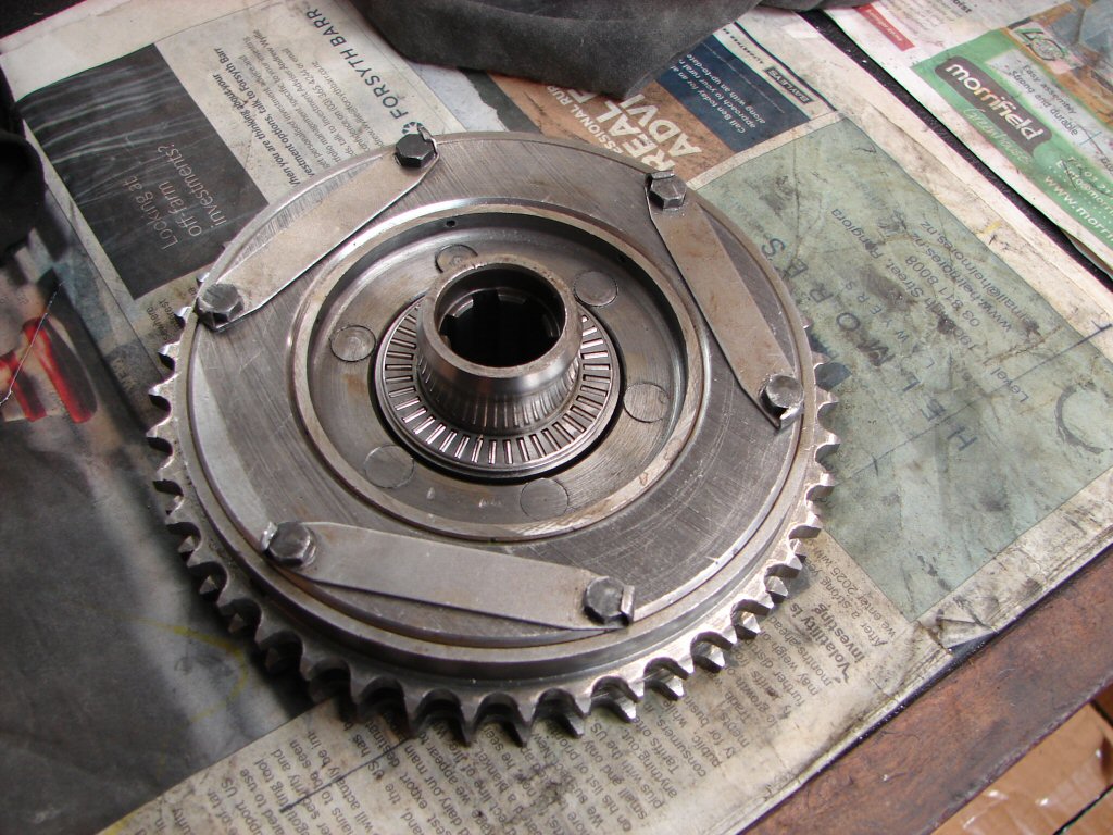
What we are looking at is the rear of the cush drive. That radial bearing should be on the front, and takes the thrust loading when operating the clutch. Perhaps the dismantler just put it here so it remained with the rest of the assembly, although when I removed it there was a good coating of old oil keeping it stuck in place. If it was running like this for very long I would expect there to be some extra wear on the face where it should have been, which would now be running against a steel thrust washer - albeit well lubricated by the oil contained in the primary case.
Anyway, the current idea was to check the condition of the cush drive rubbers, so I should proceed with that as the most necessary agenda right now. As luck would have it, the rubbers were indeed quite new, so we may be lucky with all of the suggested scenarios.
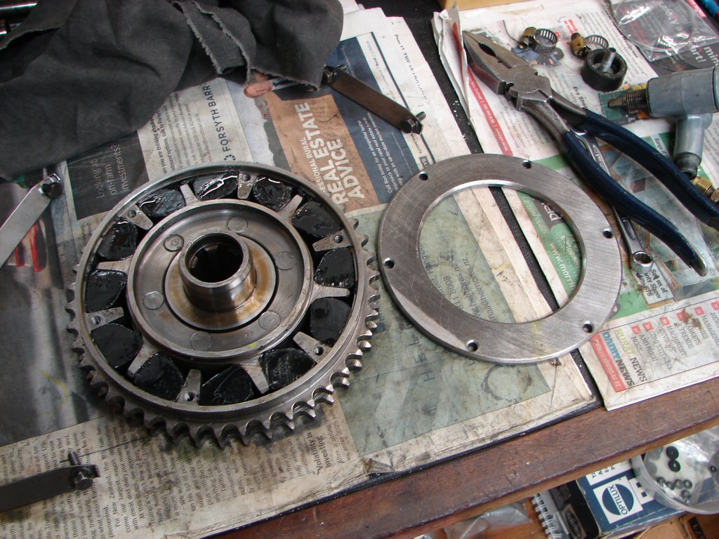
So that got cleaned up and put back together with a clean bill of health. I must say - I was ready for something to go in our favour...
The face which the bearing should have been working against showed some quite visible wear, as many do, but there were no signs of distress such that it should not perform its task as well as required. I thus considered it to be time to throw it all into place, which meant checking that all previous parts had been fully tightened and locked in place where it is intended.
That gets us to here..
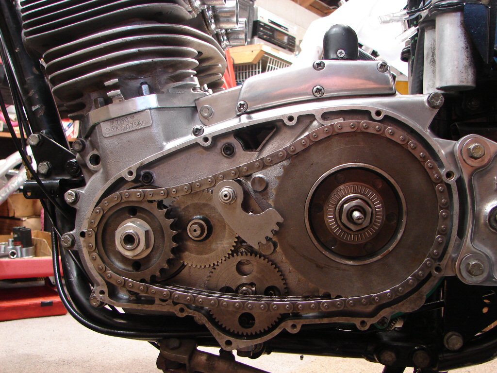
All that remains within the primary to complete it is the final tightening of the two main nuts, the front sprocket with its locking tab and the cush drive, which first needs its oil seal for the pullrod to be fitted. However, it is important to make sure that the primary chain alignment is within tolerance, so there needs to be a trial fit of the outer cover to get the cush drive sitting where it normally lives - against the radial bearing - before the alignment can be measured. So that comes next.
Meanwhile I soldered a pair of tails to the original neutral light switch, having made sure it functioned, and it is set to operate at least in a cold engine. I have found that these switches often need readjusting when the engine is hot, as normal practice is to avoid too much preload on the camplate in the gearbox by the switch as it makes gearchanging more difficult. For this reason I am leaving the wires disconnected for now, as once they are pressed into new bullet connectors they do not come apart easily, so best to get things adjusted under normal operating conditions before doing so.
The oil pressure light switch to the right is good to go as it switched back on some minutes after the oil pressure I supplied had bled off, so it is functioning normally thus far.
Happy with progress today.
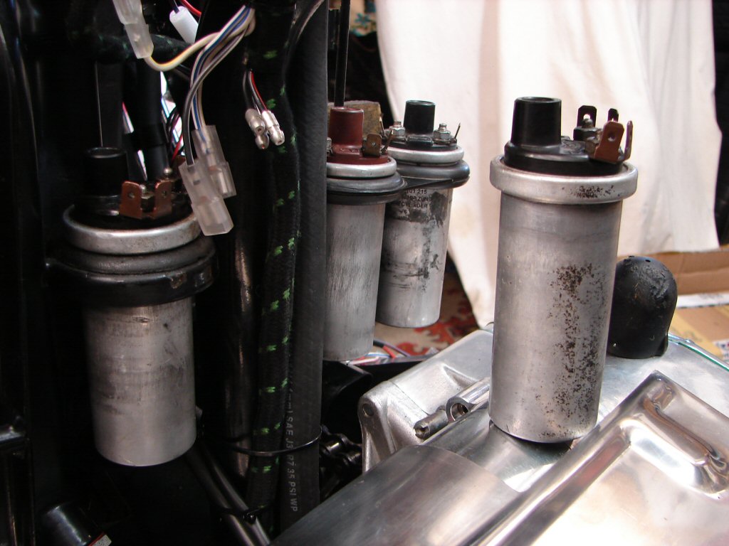
As the wiring is proceeding front to rear it was time to fit the Trispark so its harness could join the fray. Before beginning this process I decided to check that the ignition coils were healthy, as one had already been replaced so at least one Lucas OEM had expired to date. The replacement item was on the centre cylinder and was of German manufacture. I have come across a lot of these type and they seem to be reliable enough, and are obviously being supplied locally.
I was glad I checked, as another Lucas coil was reading high on the HT side, and while I have no idea what effect that might have on its ability to produce a good spark, it is a certain sign that the coil is changing which usually means windings are misbehaving. As I had a good used coil from the same German company I fitted that and the old Lucas will find its way to the bin. Or maybe the scrappie.
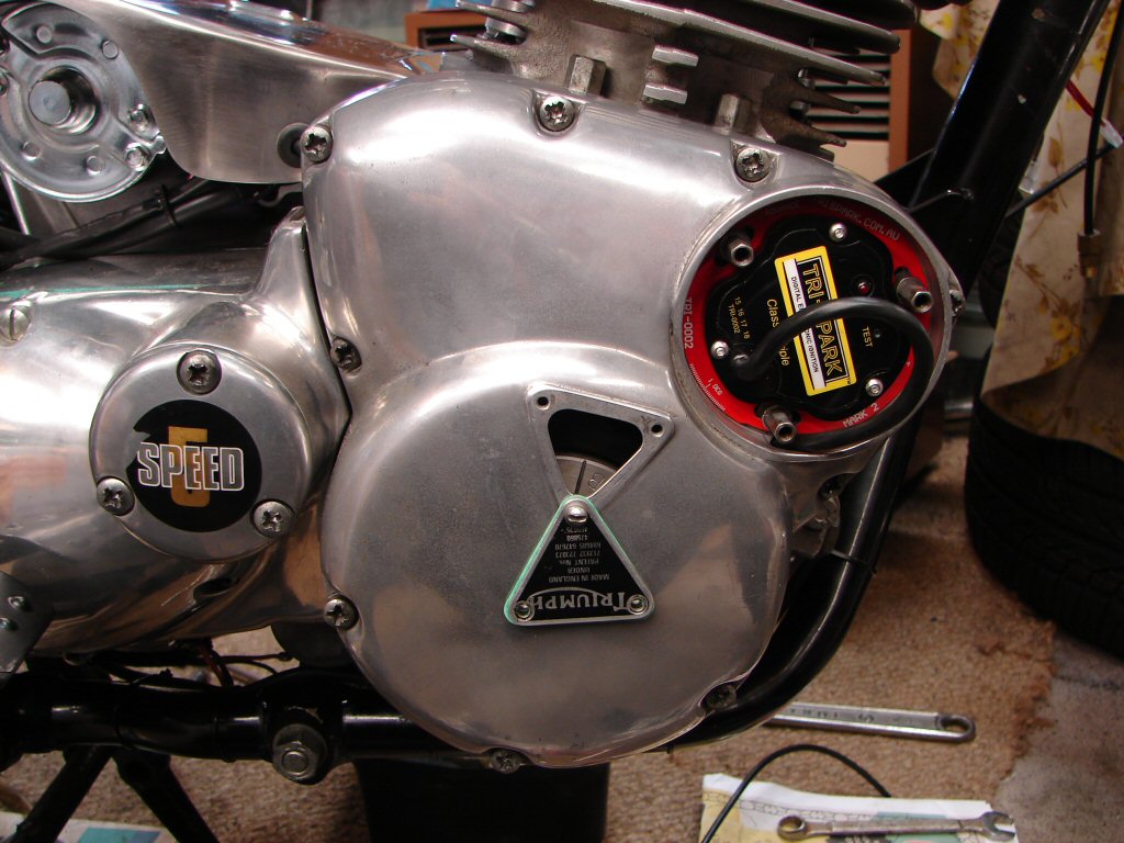
The fact that we now have a working kickstart thanks to the primary chain being in place made it a cinch to move the engine to No.1 cylinder on its firing mark, checked by both the crankshaft drilling and the 'B' timing mark on the alternator rotor.
The rotor was easily moved from its previous position for the Boyer to the new measurement of 22mm between the dot and the centre of the forward stud hole, so got tightened there. The allen screws can bottom out in their threads and I had already decided to use the old Boyer version which worked better than the one supplied with the Trispark. Still, I tightened the screw without a washer until it would go no further, then counted the number of turns it had gone as I wound it out. Now I fitted the washer and counted the turns on the way in, and it tightened up 3/4 of a turn earlier, so I feel confident that it is properly tight. I have been caught out in the past when one came loose and the rotor moved, causing a trailer recovery from quite some distance, and I do not intend that to happen again. That one was down to the washer being too flimsy and buckling during the tightening, so it doesn't take much for them to loosen off in service even when you think they are probably not going to come out of the taper even if the bolt was not getting the best grip.
The unit now went in and is pinched at mid-adjustment until we get the elctrics working and I can use the LED to get the static timing spot-on.
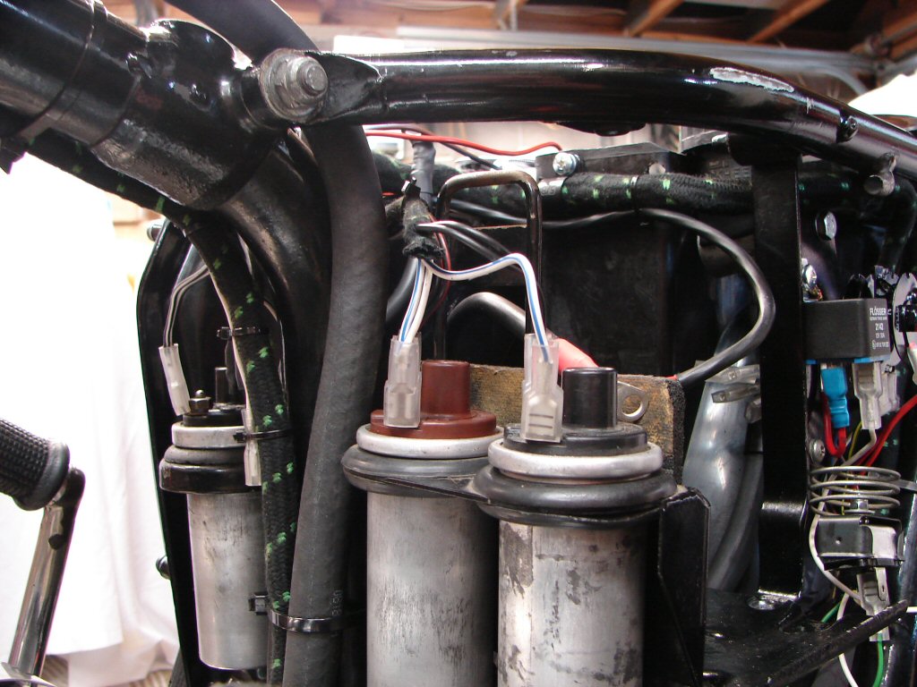
The Trispark harness now got run all the way back to the battery tray area, with plenty cable ties securing it and all the other wiring going in the same direction. They provide a good length on this harness which can be seen tied to the underside of the main wiring harness and curving around just behind the new ignition relay.
All of the original coil wires in the main wiring harness are reconnected to the coils which only need one terminal per side, and the wires are all coloured as they are shown in the factory wiring diagram. Those same wires travel around the battery compartment and their other ends, which used to be connected to the condensers, can be made to exit just behind the accessory plate right behind the relay, where you can see four spade connectors sticking out.
There are five wires in the Trispark harness, four of which connect to the spade connectors, and the main power feed, which connects to the relay. The connectors then get tucked in behind the accessory plate and can easily be accessed if needed by removing the battery. As I spend a lot of time faultfinding electrics I know how pleasing it is when the wiring diagram and the actual wiring tell the same story.
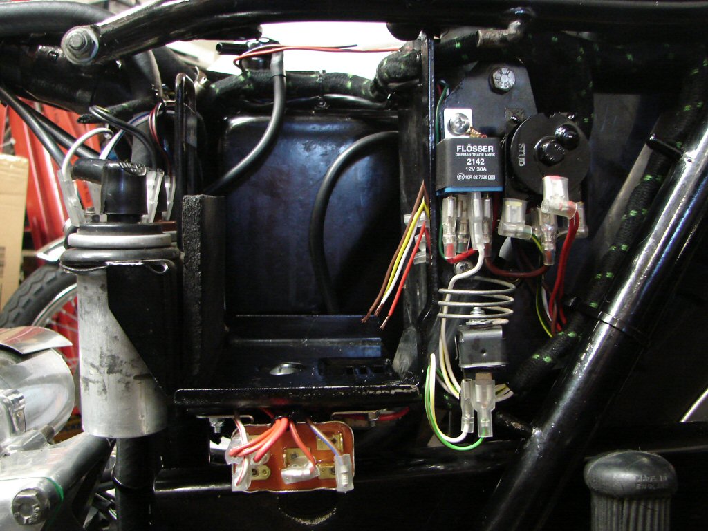
Electrics continued to be the main course with the final installation of both the ballast resistor and the starter relay, and also involved the continued use of the original wiring wherever possible. The ballast resistor resides beneath the centre of the battery tray, with the starter relay exactly where the factory intended on the front lower edge, so all the necessary wires were well placed to reach their intended target, as were the wires from the starter which operate the solenoid.
The flasher unit looked as if it might collide with the sidecover, even though it is where it should be, but a trial fit of the cover showed that they would co-exist happily. The ignition relay and the rectifier are all complete and the only remaining task is to join the Trispark wires to the coil feeds. That will have this area sewn up, although there are still a gazillion wires in the headlight area to play with...
For some mechanical light relief I tried to trial fit the outer primary case, which I then found had to be fitted before the rearset peg mount, so that came off again. with the cover finally on I pulled the clutch assembly outboard to its normal running position then whipped the cover off again to check the primary chain alignment, which was very slightly angled inward at the rear sprocket. That is exactly as it should be as it will be brought outwards by the thickness of the cover gasket on final assembly.
I had marked the position of the gearchange foot on the cush drive face through the small aperture in the outer cover, which is there for timing the gearchange cross shaft. When I took the cover off it was apparent that the timing was out by one tooth, which is also one tooth of the spline at the gearbox end, so I loosened the nuts at both ends and made that adjustment, after which everything lined up spot-on.
The original philips head screws around the primary cover were in fairly rough condition, and despite running a die nut down each one they were a bit tight when fitting. It turned out that there was also one missing, so I paused at that point.
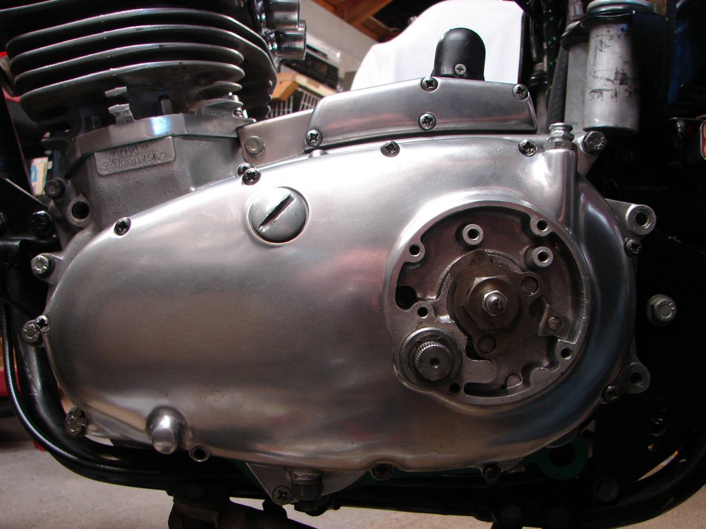
Checking the parts stockists for these screws showed that they were available, but at quite a price. By comparison, a set of allen screws for most of all the engine covers would cost about 1/3 of the price of the original screws for just this case.
I made a command decision...
While waiting for that to bear fruit I continued by fitting a clutch cable to see how it fell into place. Not very well actually. The handlebar design means it is not possible to arrange a very gentle bend up front, which often leads to a fairly heavy clutch action. We shall see. The primary end also had some issues, mainly because some of these cables have abutments which are in no way related to the adjuster they are intended to locate in.
Besides allowing the cable to wander about this also encourages oil to leak around the entry point, which only causes owners of "other" makes to criticise your bike for having the "usual" oil leaking habits. This shits me to the point that I take extreme care to try and eliminate all such issues before they happen.
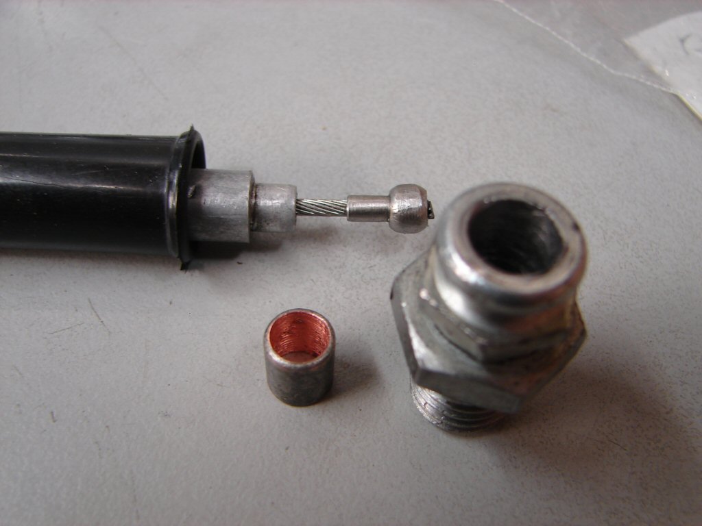
So I decided to make a reducer which would make the cable a firm fit. Unfortunately the reducer was too small to allow the oversize nipple on the end of the cable - which would not fit into its swivel in the operating lever either - to pass through, so that had to be reduced as well.
So here are the finished pieces before assembly. The reducer sleeve was made from a large electrical terminal and required 1/64" to be drilled out of the adjuster to accept it. Being made of copper it was easy to work with, and I opened the I.D. of it the bare minimum so that everything is as firm as it can be. Yes - the nipple now just fits through it and also locates better where it lives.
There are a variety of opinions regarding the size of the three ball bearings which sit behind the clutch operating lever. They began life as 1/4", but owners have experienced some improvement when using larger balls up to 7mm in size. I trial fitted a set of these in this case, but found that they caused the pullrod to sit futher enough outboard as to risk colliding with the inside of the cover plate.
Once when riding my T160 in Brisbane I was sitting at some lights when suddenly I was underway. I thought someone had run into the back of me, but there was no other traffic, and I soon discovered that I could no longer free the clutch. Upon inspection I found that one of the original 1/4 balls had neatly split in half. The nearest size I could find nearby to replace it was 6mm, which is slightly smaller. To my delight the clutch seemed noticeably improved, which may mean that the faulty ball had already been in trouble for some time, but whatever the reason, the 6mm balls are still in there and I have a delightful clutch, so I have fitted the same in this bike, with the bonus that it provides the greatest clearance between the pullrod and the cover that can be had.
Here's hoping...
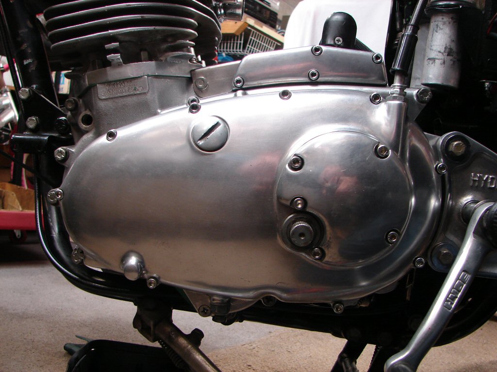
So a trial fit was in order, and the cable is nicely secure, although not yet fitted properly as the adjuster is missing from the clutch lever on the bars, so I now need to find one of those. The cover plate cannot be fitted while the rearsets are in place, so they cannot be finalised and adjusted until all of the above has happened.
Spot the shiny new allen screws which now adorn this side of the cases. They are such a breeze to tighten - pinched but not strained - and it is nice to be able to do so without surface damage such as that experienced by philips head screws once they have been in and out a few times. The countersunk head screws are not supplied with the kit so the originals remain in place.
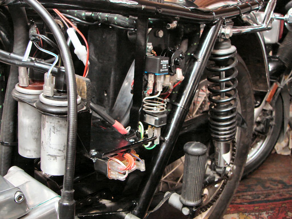
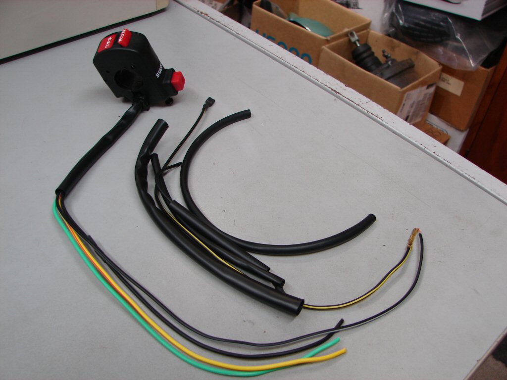
The wiring is now all complete in the battery tray area and attention will move to the headlight next. I have received the new switch which will be fitted next to the twistgrip and restores both killswitch and starter button features - once I have figured it out that is..
The new switch had some extra wires whose purpose is unknown, but they were hanging out the side of the harness, so they got cut off. I used a meter to ascertain which of the four remaining wires went to switch and button, then trial fitted it to see how the wires would perform. First discovery was that the "compatible with 7/8" bars" did not apply to our bars, so I opened it up and found that it was not fitting together correctly due to bits of plastic colliding with other bits of plastic, so a round file cured that. With the switch unit now in position it was obvious that the wires were too short apart from one. so followed an "extending wires" process which was today's main theme.
Other wires which also needed extending were the three that came from the small aftermarket indicator switch on the bars, and I was able to use the original coloured wires so any troubleshooting in future will be easier to tackle.
Once those wires were complete I tested the switch to find that the right side indicators had no output, so that switch came apart too and I removed 16 years worth of rust then oiled it, after which it decided to behave.
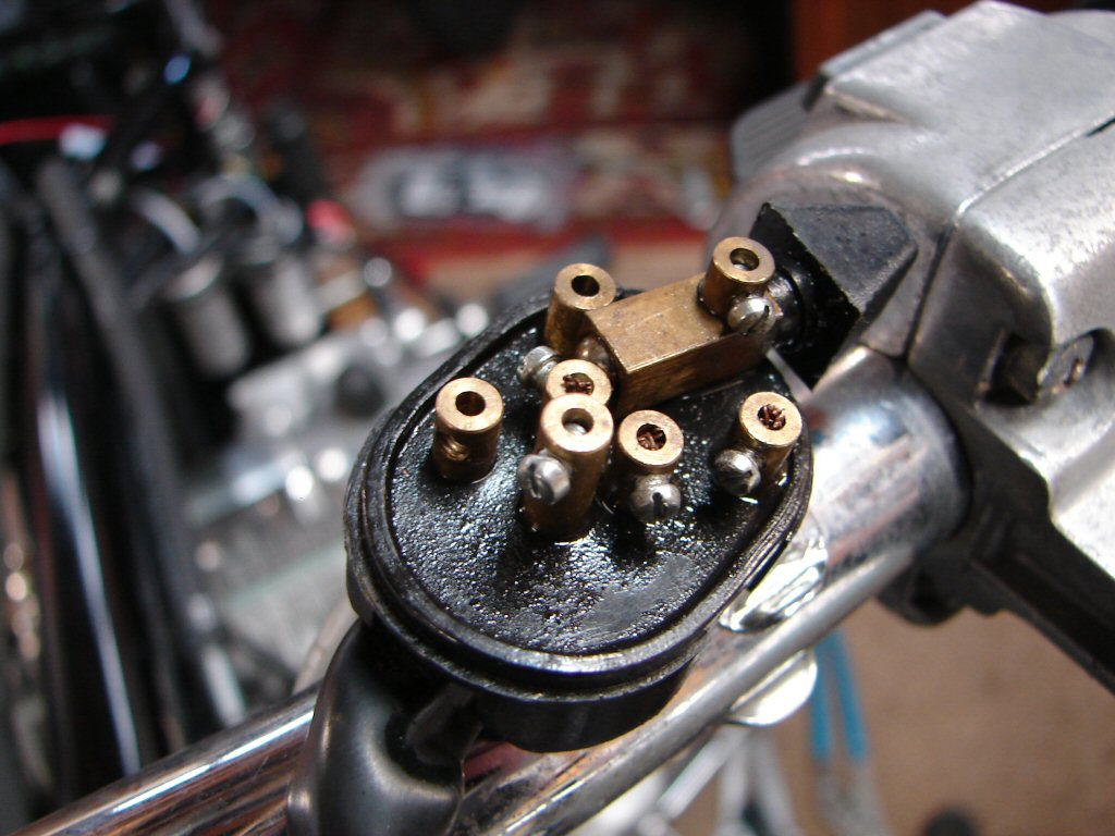
All the extended wires then had bullet connectors soldered on and were fitted into the connectors that will hopefully allow them all to do their jobs reliably. I took some care to keep the bulk of the connectors in the lower part of the headlight shell, as the headlamp plug sits well back into the centre of the shell.
The final two extensions in here were the two which connect to the switch in the top of the headlight, as they had also been shortchanged.
But wait - we are not out of the woods yet.
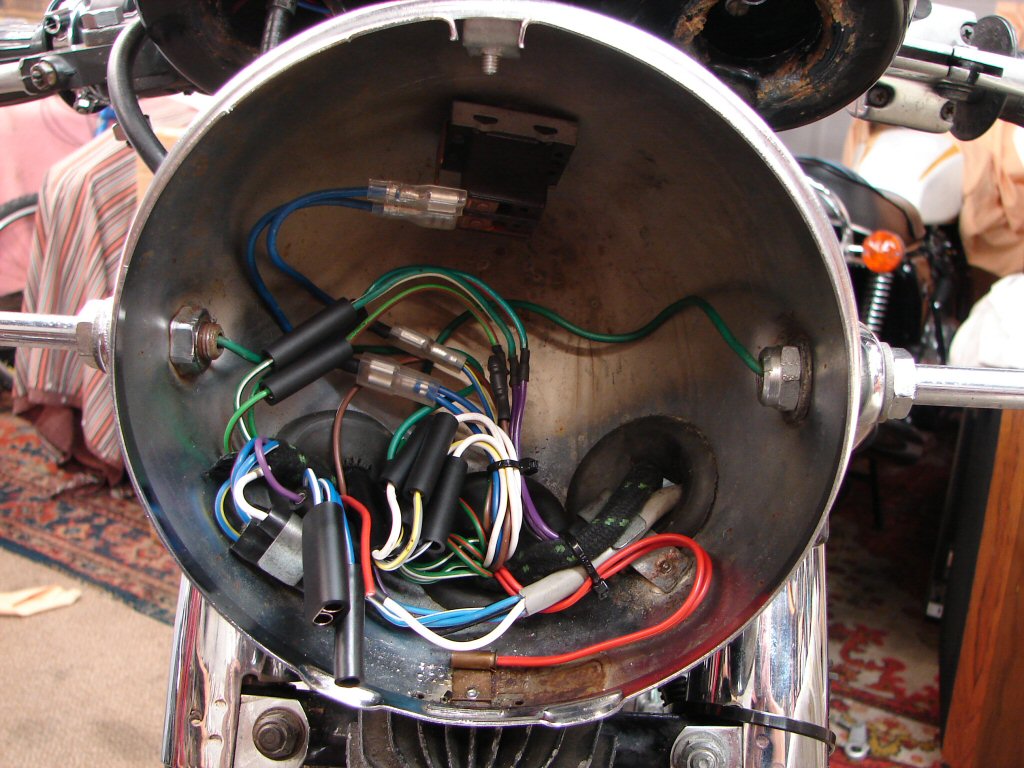
Before fitting the connectors the meter was used again to ensure that the right switches were about to connect to the right wires in the main harness. While they all turned on and off happily enough, it became apparent that the new "Run/Off" killswitch is on when it should be off and vice versa. Strange that there was no mention of that in the blurb.! I am torn between two options now. Either I pull it apart again to see if I can reverse the sense of the switch, or we leave it as-is and treat it as an anti-theft measure...
The good news is that the headlight wiring is nearly complete, with just the plug for the actual headlight to be connected after its tiny wires have been upgraded. That means I shall be moving upstairs to the ignition switch area where another nest of wires are waiting to be sorted.
Strangely enough, there may be some wires that need extending in that lot too, as the light inside the oil pressure gauge was connected to stuff that no longer exists..
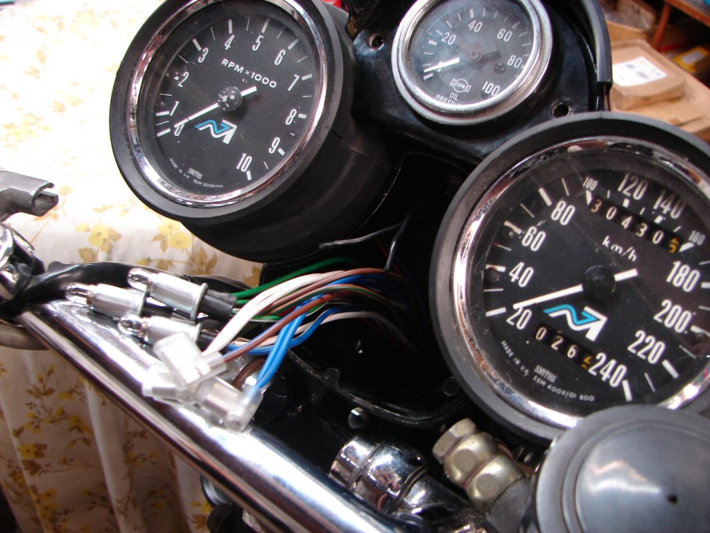
After a brief interruption due to life on the planet, I got back to the wiring side of things. The oil gauge light wires got extended and mated to the wires going to the speedo and tacho lighting first, then the ignition switch and idiot light panel got assembled before the clocks went back in for their final fit.
While untested as yet, this is the last of the wiring work except for the actual headlight itself.
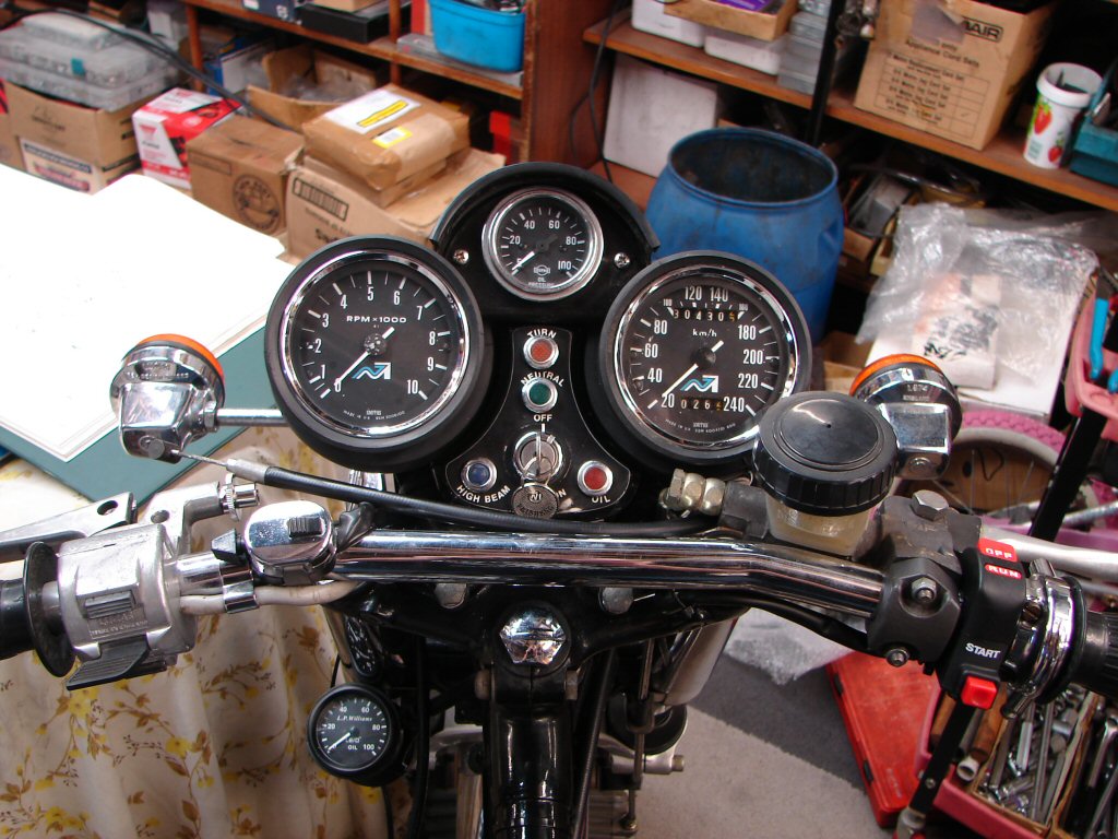
The tacho drive came apart to be cleaned and lubed, and I took the opportunity to add an O ring inbetween the input shaft bushes while it was apart. I had a previous T160 with an annoying oil leak from the tacho drive and this was the cure I invented for that, which is still working. Seeing it was apart anyway I figured it was a good mod to apply.
With that fitted the tacho cable got added and both gauges had their cables attached as they went in. Unfortunately there is a brake fluid line which now argues with the tacho cable on full lock, so I will have to undo that cable again and switch it to the other side of the brake line.
Always another narky problem...
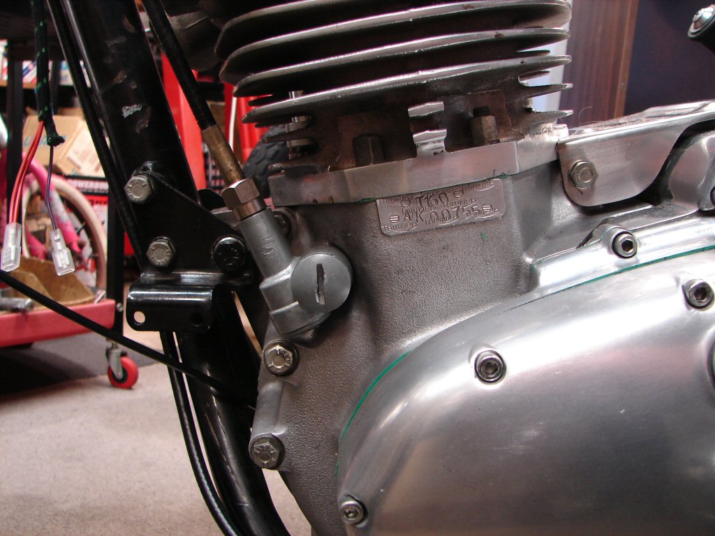
Final move today was to install the clutch cable at the lower end prior to fitting it into the handlebar lever and adjusting it. However, with the tight bend it suffers at the steering head the cable was quite stiff to operate. I straightened the cable to see how much better it was when straight, only to find it was exactly the same. I think it needs some light oil down the inside of the cable.
I do this by cutting a bottom corner off a small sealastrip plastic bag, pushing the cable in through the cut corner then pvc taping the bag to the cable. Then you can half fill the bag with 3-in-1 oil and retain the cable overnight in a vertical position while the oil all runs down the length of the cable.
No mess Charlie.!
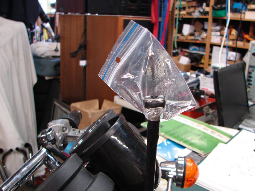
Actually, the oil disappears while you watch it, then I add a little engine oil just to be sure it retains as much as possible. The light oil can be felt on the cable down in the clutch operating lever dept within an hour which signifies that the cable has no restrictions.
With that done I fitted the cable to the handlebar lever after greasing the lever pivots and the threads on the adjuster, although I think that the adjuster will remain in the fully in position until the cable and clutch have done a few miles. The lever action has improved a lot with all of the above, and the clutch is set to free up at half travel which is my normal setting prior to any test runs.
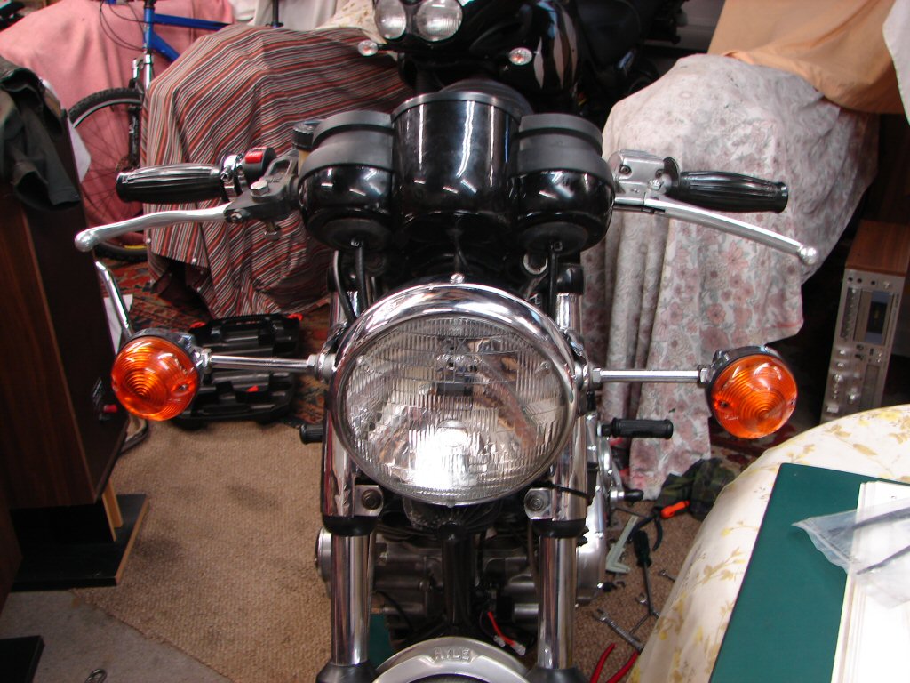
With the clutch adjusted I was able to do a final test that the pullrod did not interact with the cover plate with the lever fully in, and that was all good. I leave the finger springs and holding bracket out of the mix down at the operating lever - anything that makes the clutch action lighter is to be encouraged.
With the cover and its gasket in place the rearsets and gearchange linkage could now also be fitted up. It is a shame that the gearchange on the rearsets seems to introduce a bit of vagueness to the gearchanging action compared to the standard setup, though as I have yet to experience it under use that may just be my imagination.
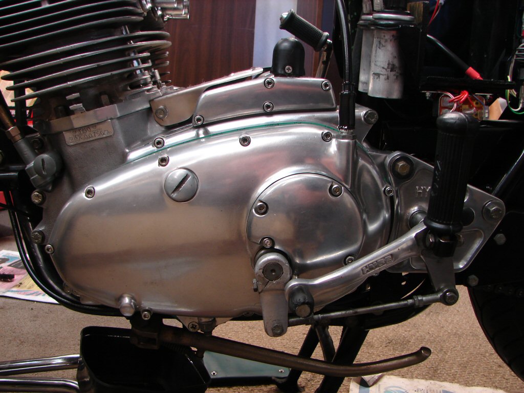
Next job is to try and restore the original oil pressure gauge line, either by using a new olive I was able to source, or better still, to recover the original olive by melting the remains of the old line out of its tiny recess by use of a gas flame, as it is a more robust and elegant solution. After I go get a new propane bottle of course...
After a more thorough inspection of the original olive it became apparent that all the propane in the Hormuz Strait was not going to revive it, and it was also discovered that an intermediate joint in the oil line to the gauge had exactly the same olives as the one I had been able to source. That made the decision easy. New olive fitted and the line secured to the oil gallery, which meant that the exhaust system could now be fitted.
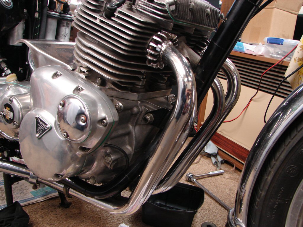
When I say "could be fitted" I mean it would be appropriate. Actually getting the thing to go together was another matter. This is a "Legend" style such as Les Williams designed, on which the two centre header pipes now siamese into the outer headers just aft of the lower bends, but this introduces a real fiddle when trying to coax the centre pipes into the one-into-two alloy manifold in the centre exhaust port.
The final recipe was to have the outer headers only just sitting on the outer edge of their stubs, the inner headers resting in the manifold while it floated in midair, then wriggling the whole lot rearwards while forcing - that would be a good word - the manifold to go back into the port while the rear end of the centre pipes enter the outers simultaneously.
I had wondered why the exits from the manifold were quite enlarged, and now I see that they have to be or you would never get it to fit at all.
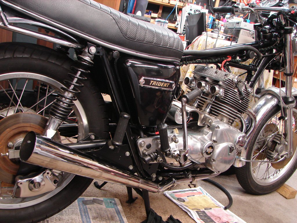
The mufflers are not really mufflers at all. They are amplifiers, being only a steel outer with no internals at all, although a hole at the outer end suggests that baffles were once fitted, or could be. This does not bode well for test running the beast around the neighbourhood, although I remember when I lived in Diamond Harbour and rode my T160 to work in the Port of Lyttelton - 17 scratchy miles away - I would sometimes leave my blackcap mufflers off for the trip, just as a special treat. Unfortunately, the local law do not seem as attracted to the sound of a full noise triple as we are...
Well - they are, but for less pleasant reasons.
Anyway, these muffler look-alikes have an entry hole that is larger than the header exit pipes, and have no side slits which would allow them to compress inside their clamps, so I shall need to use some brass shim to fill the space between the two, or they will rattle around until something breaks. The blackcaps used to crack above the mounting bosses if the clamps to the headers were not tight enough, as the weight of the mufflers made them roll around the pipes, stressing the welds until they surrendered. At least these aint heavy.
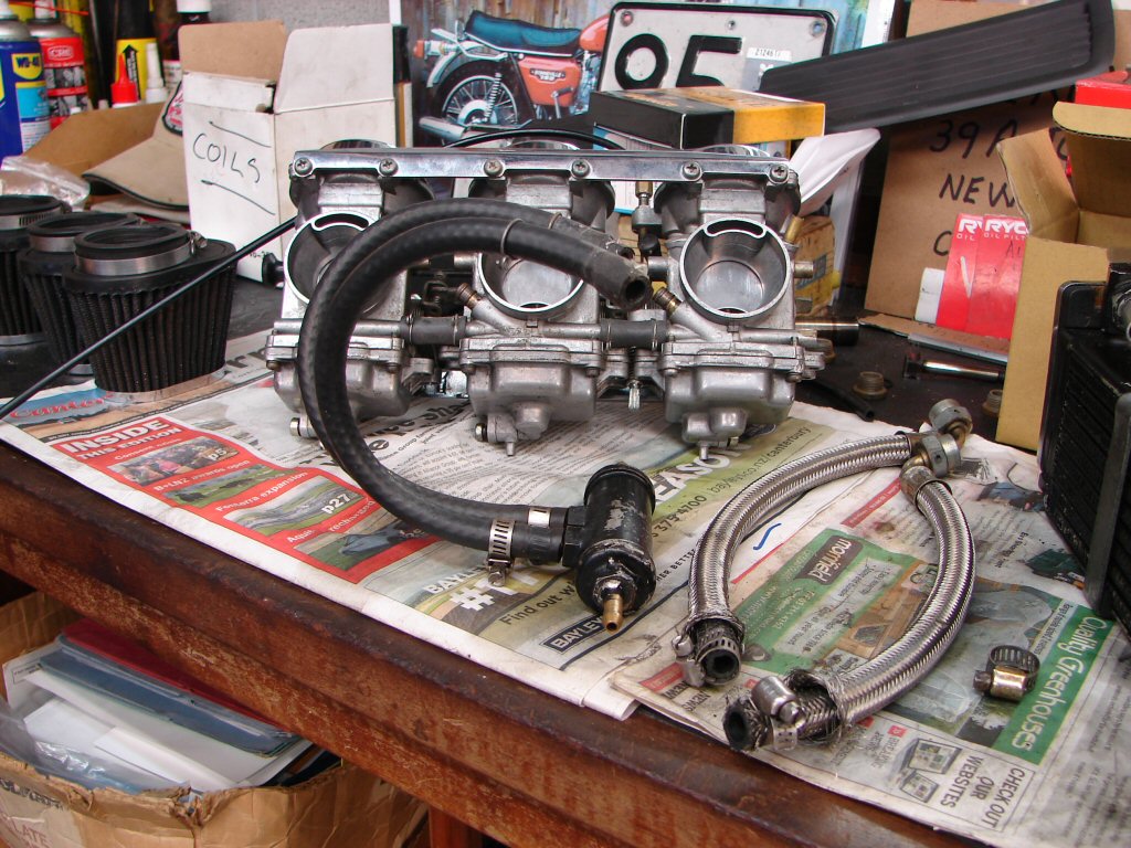
I have begun work on the carbs, which still have some form of soup inside them, so will need an extensive cleanout. The first thing I discovered when removing bits is that these feature examples of both the largest and smallest fuel delivery pipes in common use. I consider the braided hoses as nasty in the location they reside, as strands of stainless keep attacking your hands every time you work near them.
The other mechanism could have been a filter, but as it cannot be opened I guess it is just a manifold, but it sure isn't going to let a lot of fuel through. You wouldn't oughta be riding a 1000cc triple without both fuel taps turned on, let alone with pipes this small between the tank and the carbs, especially as both ends of the manifold feed only one of the two separate lines to the carbs each.
Major design flaw and potential piston eater here.
It can be seen that the carbs are all linked together to share fuel, so my idea would be to simply take each line from the taps straight to the carbs, which have a larger fuel entry than the manifold does by quite some margin.
Meanwhile I reviewed my ideas about flushing the oil cooler. Considering the length of time it has been sitting it would seem appropriate to at least use some type of solvent as a first measure. While I always flush oil through the oil cooler then discard it after first start, there may be more sludge in this one which might need more encouraging to leave.
So I chose petrol, being the cheapest version, and poured a little over 300ml in via funnel and hose until it left at the other end. That then sat overnight, after which it got some vigorous shaking then was blown out into a car sump to observe the contents.
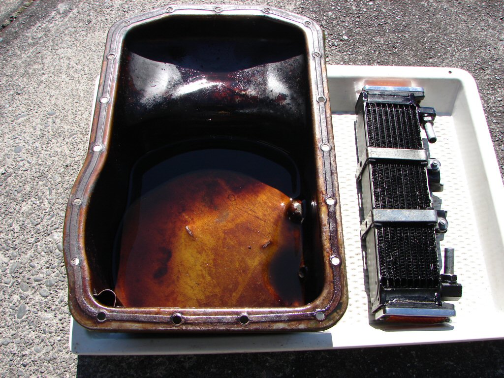
Pleasingly there was very little to the tune of bugger all sparkle to be seen, although the dents and scratches in the bottom of the sump make it rather unclear, and certainly only tiny specs which would not be prone to lodging inside the finning. I cleaned it all up and proceeded to squeeze it into its normal space.
I removed the exhaust rocker box cover to make it easier to shoehorn in, and then tightened everything up in the order the bracketry demands. I was pleased to find that my minor mods to the mountings had created some clearance, and it may even be possible to remove the cover without loosening the cooler in future. We will certainly be finding out soon enough.
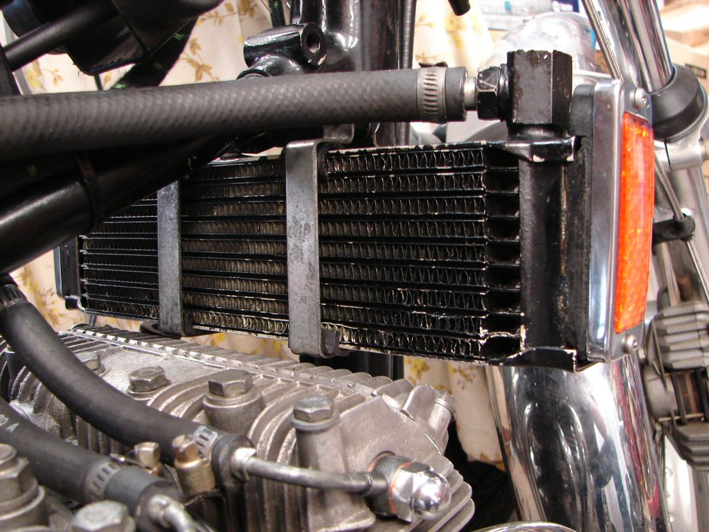
The horn was an easy task to refit next, and the wiring managed to just reach and no more. There was a missing tacho cable support bracket that keeps the cable away from the exhaust system, so one of those got fitted as the rocker box cover went back on.
Next job was to fill various oils, starting with the gearbox, where I use a synthetic 75W-90 to great effect. I place newspaper underneath to see if any drops dare to appear, and as they did not I gave the rear wheel a number of turns to spread the lube around, then a number of strokes on the kickstart lever to do the same. On about the fourth kick there was a distinct 'sprong' noise and the lever gained some extra friction. It also now parked at a rather low angle.
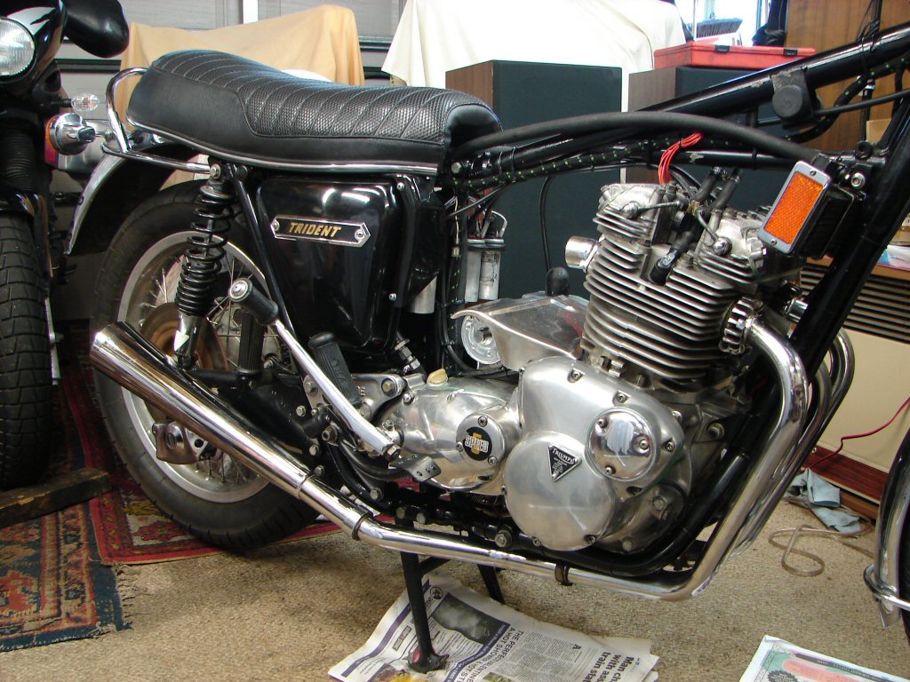
The only two options that seem likely are that the new return spring just broke, or it has managed to come off the peg which holds the outer end of the spring. I am now half way through draining the new oil out again. The drain plug is inaccessible due to the exhaust collector, so I removed the camplate plunger instead. Next the rearsets and the outer gearbox case will have to be removed, so I decided to sleep on it instead.
Two steps forward, one step back...
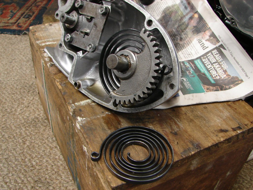
So everything came off, and finally the outer cover itself, to reveal that the spring had managed to escape its retaining pin. The pin was a lot smaller than the hole in the end of the new spring, but less so in the original spring, which had a better formed loop on the tail end. The old spring is also of greater cross section, so needs less preload to give the correct amount of parking tension.
Regardless of which spring goes back in, there needs to be a sleeve on the pin to reduce the free play between the two, as this seems to have encouraged the escape plan. I now need to remove the kickstart lever so that everything can be worked on more easily.
I am tiring of going backwards, but you don't know until you know...
The kickstart lever came off without a fuss, much in thanks to the work I did on the cotter pin during the assembly process. They are always in need of some cleaning up, but we do benefit when carefully fitted parts need to come apart again unexpectedly, as they do so in a compliant fashion.
I could not find any form of sleeve I could fit to the locating pin, which is only 3/16" but fits in the considerably larger loop in the spring. Having chosen to re-use the new spring I instead closed the loop up a bit in the vice, which worked well enough to seem it would not easily escape again. I then experimented with various preloads of the spring before being happy that it would park the lever firmly without offering too much resistance to being kicked through its complete range of travel.
Something had to be responsible for the spring dislocation and I am not taking chances, so avoiding any risk of coil binding of the spring has been a necessary consideration, as it has one extra coil compared to the old spring.
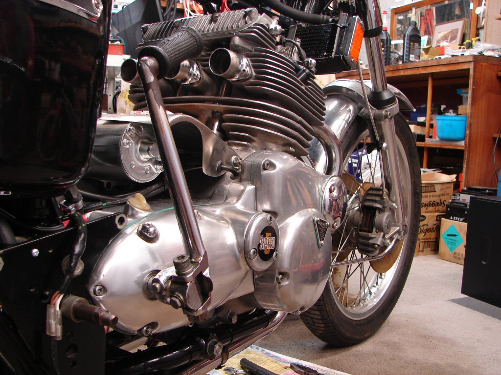
So here we are all back together and awaiting the adding of oil for the second time. I intend to give it plenty of action before I put the rearsets back on - just a kind of insurance policy you might say.
I also located the source of a rubbing noise that had happened when I was first kicking it over in gear to spread the oil around. The rear wheel has been changed to an 18", and the monster 120/90 tyre rubs against the chain for part of a revolution. Not sure if the rim is buckled or the tyre not seated on the rim all the way round. The inner edge of the chainguard has been hacked away to give clearance in the same area, so I will just make minimum clearance by altering the wheel alignment. The tyre looks pretty new, so it may respond to some cornering work and wear down a tad.
Reckon I would have stuck with a 19" and just replaced it more often. I have read reports from owners who had suffered some poorer steering performance after going to 18" rear, and the production narrower front than rear rim setup was originally found to cause some weaving issues over 70mph, as the rear tyre kept trying to align with the front, and which led to Les Williams adopting a WM3 front rim on the race bikes and the Legend. I was lucky to get his last set of 19" WM3 Borranis in 1990 and have never had the slightest issue with the frame performance.
So thats nice...
Well - what a difference a day can make.
Having refilled the gearbox oil and had no leaks, and then used the kickstart multiple times to both oil things and check the spring action, it all seems to be happy in that department, so the rearsets went back on.
I had run into problems with the left muffler(?) as it was proving to have a too large inlet to allow successful shimming of the joint. I decided to add some thicker shim material but could not retain it while attempting to fit the muffler, so decided to use an old jubilee clip to hold it. Looking in the 'old jubilee clip' box, which also contains various eahaust bits, I found that I had a brand new pipe reducer. It looked about the right size but surely would not be, but might give a better result. Well - it was a perfect fit in the muffler, and I noted that a similar reducer had already been inside the right muffler, so now both sides were able to be made to fit properly.
Next came the best thing you can ever remove from a bike. The awful braided fuel lines had to go for a number of reasons, but I was keen to re-use the fuel tap connections, as I had a cunning plan to come up with a much better fuel feed arrangement.
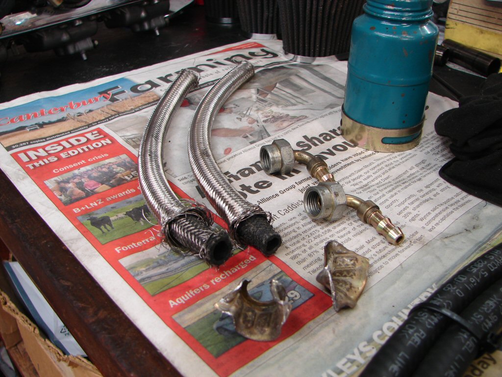
I pulled all the float bowls off the carbs and was pleased to find no fuel residue whatsoever, so it seems that the light oily stuff inside the wrapping may have been some WD40 or similar which has helped to keep things in great shape.
I trial fitted the carb assembly and noted that the jubilee clips had really long tails, and being stainless the ends take no prisoners but plenty skin. So they all got shortened in the cleanup process. The outer pair had already been done and I had just marked the centre lengths when this pic was taken.
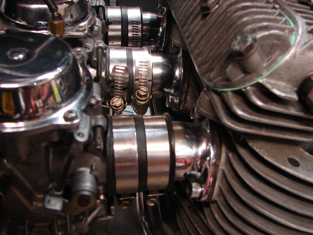
The carbs would need to be in place before I could work out the plumbing, so after all the clips were reworked they went back on and I recovered the fuel tank from the loft so it could join the mix to show me where the fuel taps were going to end up.
Happily the fuel taps proved to be exactly where I wanted, but trial fitting the pipes to the taps showed that they ended up sitting on top of the carb inlet rubbers, so would in fact exert quite a downward pressure once the rear tank mount got bolted down if I was to route them as I wanted. This is down to the fact that the BAP taps are longer in the body than original types.
That led to putting all of the parts on the bench for a serious perusal.
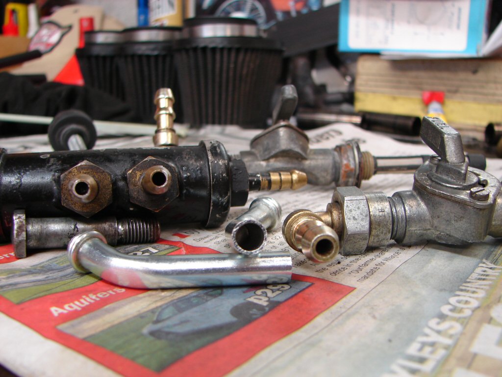
The black manifold was part of the original setup, but as all the hose fittings are only 1/8" I.D. I decided this was not good enough. As I am familiar with the internals of BAP fuel taps I know that they also have a lesser flow delivery than original style taps. This bike's original fuel tap spigots are only 5/32", so it has enjoyed a rather meagre supply of fuel in its past life, and I can only imagine running on one tap would have been a bit like Russian roulette.
There are a pair of new T160 fuel tap spigots in the pic for comparison, which are 1/4" I.D. as are the fuel inlets on the Mikuni carbs, so that is the best combination of lines that could be implemented to avoid any over-hot pistons should much full throttle come into play, but more to the point, single tap operation would be reliable so the reserve feature could be useful again.
So, my plan is to replace the BAP taps with originals, which you can look right through when they are open, so there is no better flow than that. Original spigots are available with 90 degree bends so they will be used and each will connect directly to the two carbs which have fuel inlets, but I plan to route the lines under the tank and down to their respective carbs, which is not only pleasing to look at, but keeps the lines downhill all the way.
I also managed to fit a rubber buffer to the sidestand to park against, and have soldered the new wires to the headlight connector in preparation for that to be completed when I find some bullets to solder on their ends.
End of play today looks like this...
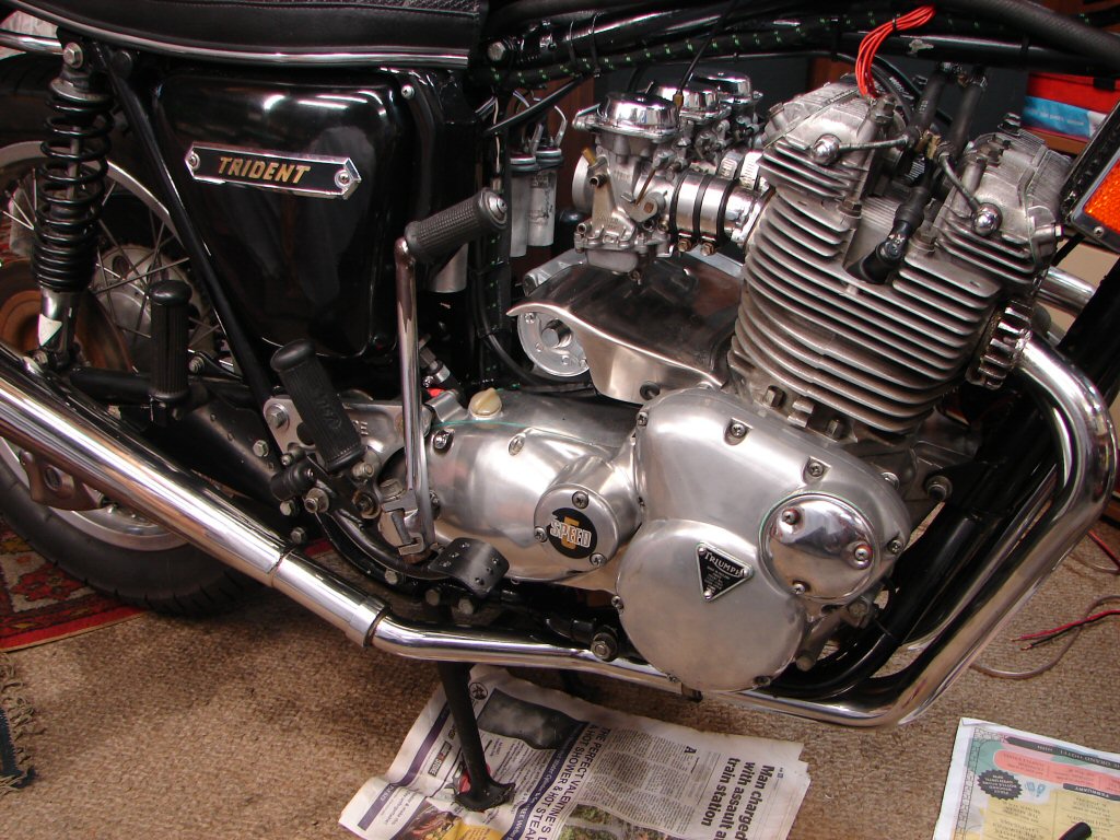
My work routine has been hijacked over the past week due to mates visiting from Perth, so as they are leaving tomorrow I should be able to push ahead with some extra time to do so.
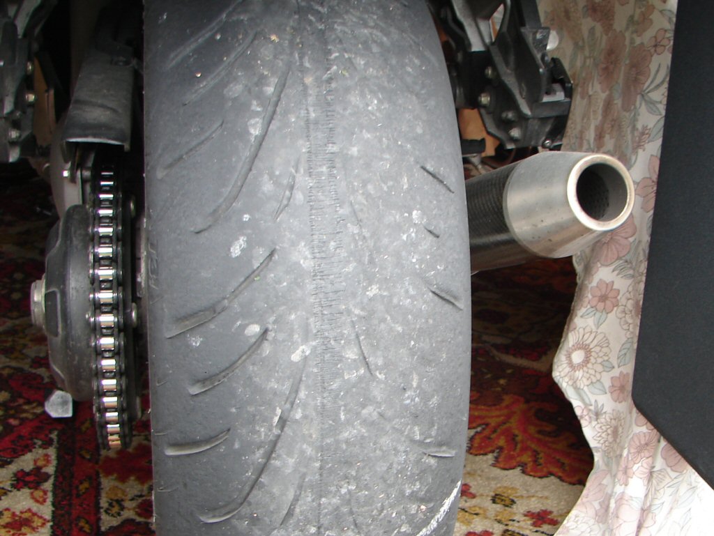
Meanwhile I have spent some very cool time totally destroying my Sprint rear tyre on some demanding roads.
Good for the soul - not so much the pockets...
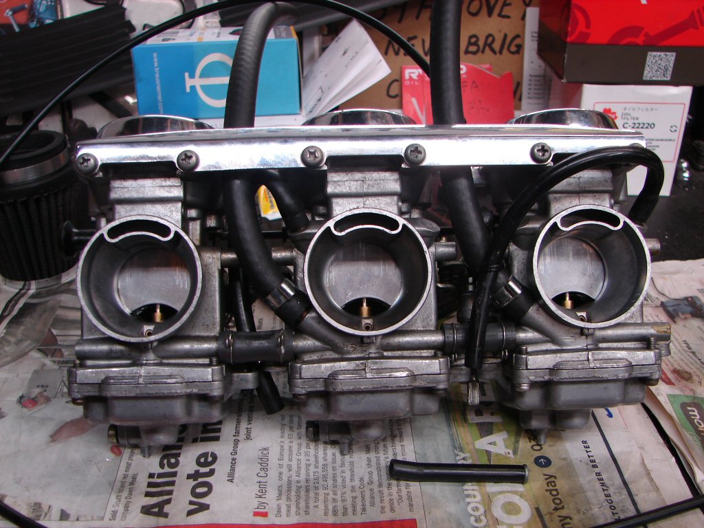
The carbs came off again to fit the overflow hoses and fuel lines, and as they interact in a rather confined space that needed to happen simultaneously. The small overflows got soaked in hot water to make them compliant, then fitted and shaped while they were still hot so they would adopt their new shapes.
The fuel lines are a very tight fit to the carbs, so I used the smallest retaining clips that I have, and are the same that I use on all fuel line jobs. They are a crimp type single use clamp, so the ears get squeezed together to tighten, then cut off should they need to be released. Forget getting any sort of jubilee clip in these spaces, they simply can't fit.
Notwithstanding any leaks I figure the carbs are now ready for their final fit. Feels like real progress.
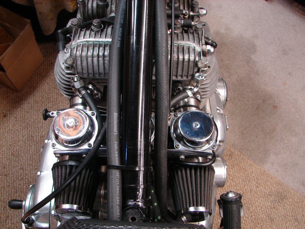
The carbs went on again and the air filters got added seeing as there is a potential first engine start in the offing. Once the first run is complete the air filters will come off again so that a vacuum gauge can be used to synch the carbs properly, but until then I don't want any loose items finding their way into the air intakes...
The fuel hoses got repositioned and shortened to their final length once all obstacles had been sorted. I am pleased with how it has worked out, and just as a side note - the original T160 publicity pics had their fuel hoses routed in this way, but it never made it to production. Shame, as the absence of them externally produces a very tidy profile.
So having said that, here is the first pic of the bike nearly complete, and the missing fuel lines are very noticeable by their absence.
I am hoping that we may be able to make an even greater aesthetic improvement on this side, because if the Madigan starter is as capable as claimed we can likely shelve the kickstart lever and leave starting up to the battery.
The fuel tank will now come off again as I need to oil the new tight fuel taps internally and externally to make them more easily operable - a common detail on new taps these days. I will also sacrifice a bit of petrol by swilling it around inside the tank and dumping it on any visible ants nest, just to dislodge any debris which may be lurking within.
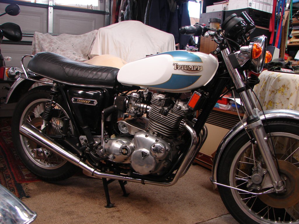
I have only done the internal fuel line routing on one other Trident, by using outer banjos which had two inlets at a small angle from each other, allowing the main hoses to feed up between the Amals and out to the taps.
We called it a 'TR7C' and it was such a slim and pretty bike that I felt it would be gross of me not to hide them that way...
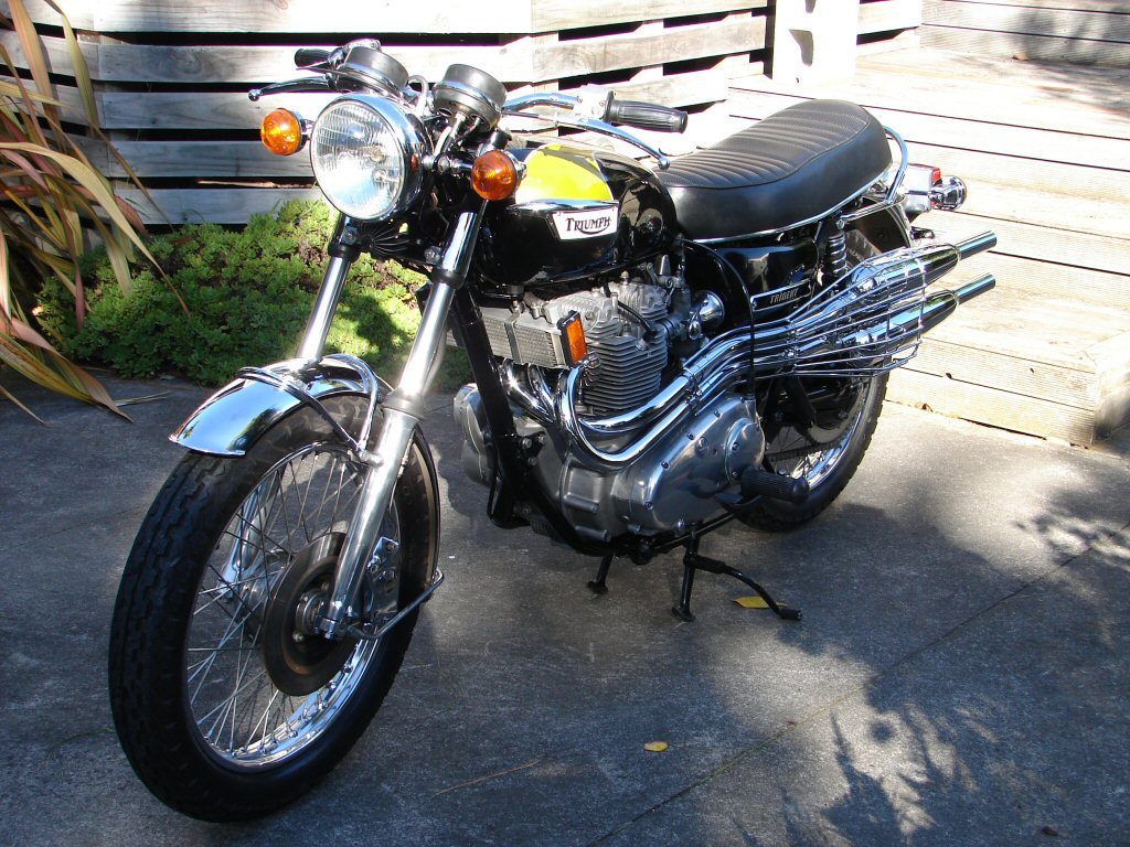
.. but I now have a feeling there will be even more.
I am not obsessive - I am just thorough.
Honest Guv...
Anyway, work continued in the form of attaching a battery to check that everything was working as intended. Apart from one crossover - two wires the same colour but doing different jobs were reversed, but as they were close together it was easy to swap them.
I did not try the electric start as the battery I used was kinda small, but was able to check everything else was working, except the neutral light switch which I had repaired but is not working because of a crappy connection to one terminal. As the problem is internal we shall need to find another.
I was also able to fine tune the timing of the Trispark now we had power, and set it using the built-in LED in the prescribed fashion.
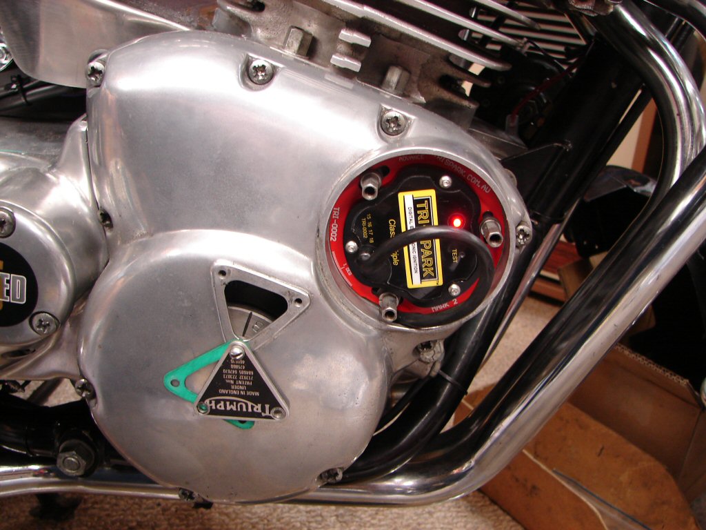
Finishing off the electrical checks I found that the headlight dip and full were reversed. As the wire colours from the connector were both the same colour it had been a 50/50 chance...
Removing the two offending bullets from their connectors caused one of the wiring loom crimp type bullets to pull off its wire, which is something a properly soldered one does not do. I find that a lot crimp connectors are prone to the same behaviour these days, so after fitting a new solder type replacement on, I also soldered the remaining silver crimp job.
We don't want any more of that malarkey.
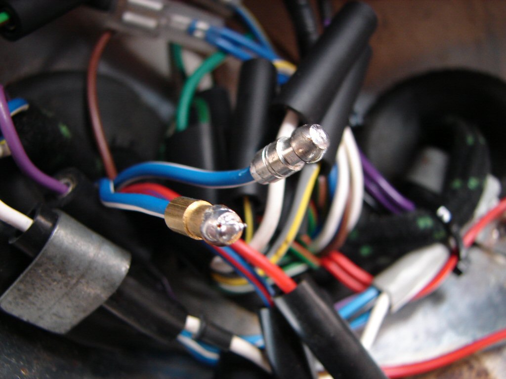
With everything now correct electrically I can close up the headlight for the final time hopefully. Everything is all cable tied to keep it away from the headlight and make finding anything in future a less daunting task.
I made one small mod after taking the next pic though - I put some red marker on the blue wire which mates to the red/blue from the harness. It will make life easier if anything like another crimped bullet leaving town occurs - but let us assume that it won't.
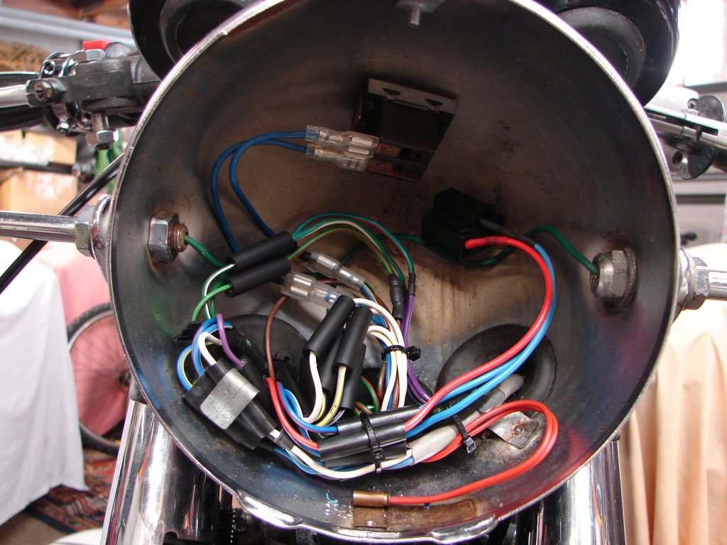
Next I will drain the gearbox oil for the second time so that the neutral light switch can be removed. I will have a try to see if it can be made to work reliably, but failing that they are easy to obtain.
I will then fill the primary and the oil tank with some GTX so that at least they are ready to go. I will also start the search for an adequate battery to take its place in the space provided and which will have enough capacity to make electric starting an easily repeatable task.
From past experience, 'easily repeatable' tends to be an oxymoron...
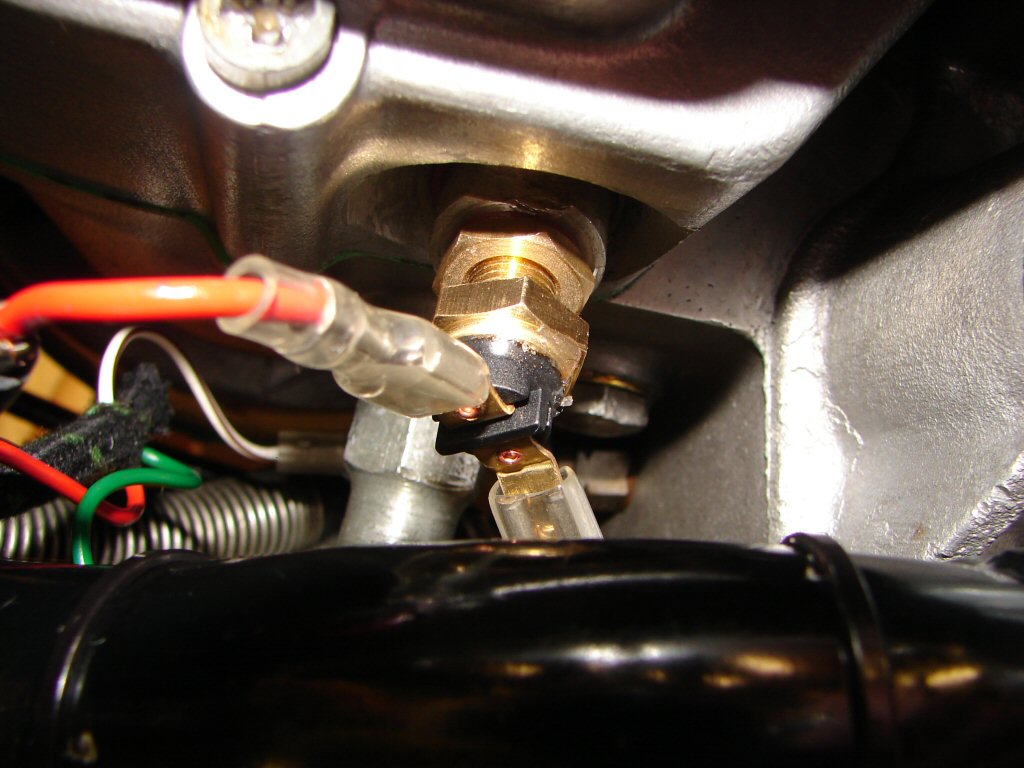
The neutral light switch was not repairable so a new one was ordered. Unfortunately Easter intervened, so it just arrived yesterday. They no longer have wires attached, just spade terminals which are mounted vertically, and must be bent horizontal in order to even begin screwing the switch into its mounting.
As this switch bears directly onto the camplate inside the gearbox, you do not want it any tighter than it has to be, or else the drag makes gearchanging more difficult. So the way I do it is to screw the switch in until it only just operates, then give it another half a turn. Often it will then fail to operate when hot, so you add another half a turn until full serviceability is obtained. Lucky it is easily accessible for fine tuning.
Gearbox is now refilled with oil for what we hope is the final time, and now I will fill the other places with oil and kick the engine over until I see it circulating. The electric start relay can be heard to operate in response to pushing its button, but as I do not have a good enough battery to crank it with I have not connected the heavy cables yet.
With that in mind it was time to fit the new battery. I think this is the largest battery that will fit in the T160 tray area without any problems, so it should have the best chance of making the kickstart lever unnecessary.
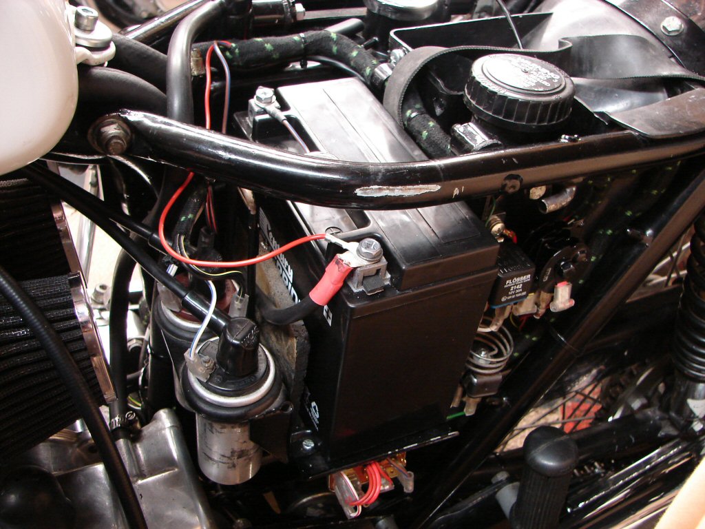
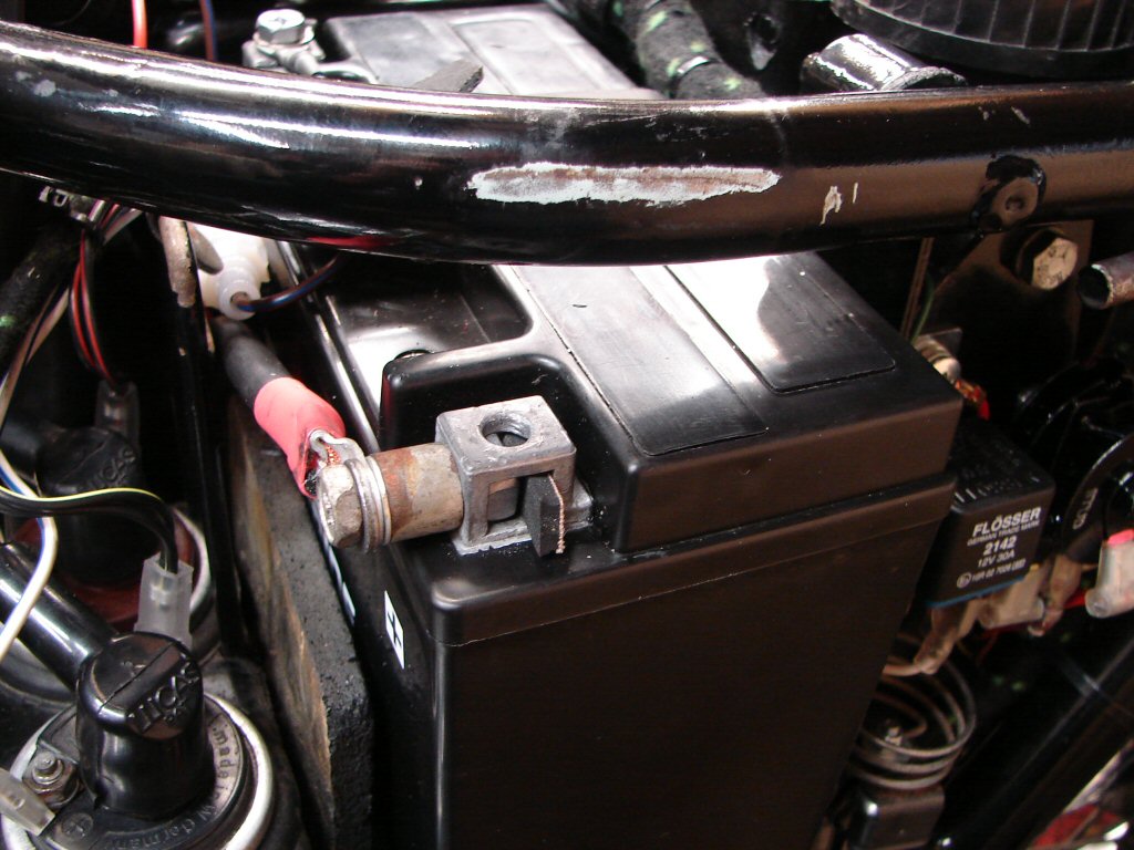
I had made all the necessary measurements before buying this battery, and was sure enough it would fit in the space provided, with a little to spare. However, once I had bolted the cables to the terminals it became apparent that the retaining thread boss on the sidecover would not quite fit beneath the frame tube as it was resting on top of the earth terminal bolt.
I had inserted a piece of foam rubber beneath the battery to discourage it from sliding about, as well as fitting a retaining strap, and I wondered if it might be just a case of removing the foam that would allow it to fit.
But then I spotted the obvious. The bolt can also be inserted from the side and the captive nut rotated 90 degrees, albeit requiring a spacer to be used for the terminals to mate to best advantage. I found a longer bolt and a spacer and now everything gets along fine.
Pleasing, but only one of a dozen small items to be sorted before we can claim to be finished.
With our battery installed it is now possible to test our new electric start. The idea is to do so with spark plugs out, so that enough oil can be pumped through the bearings that the scavenge pump will begin returning oil towards the oil cooler, which will then be flushed when the engine is first run. So a brief test was carried out on the starter, and the good news is that it whirred over briskly indeed.
The not so good news was that this was mostly due to the fact that it was not turning the engine over. The solenoid has to be working before the starter runs, so it was definitely spinning but the gears were not engaging - or - the starter was turning the wrong way.
This meant that the whole thing had to come out again.
Obviously I had been in danger of becoming complacent.
So all these bits came off this afternoon..
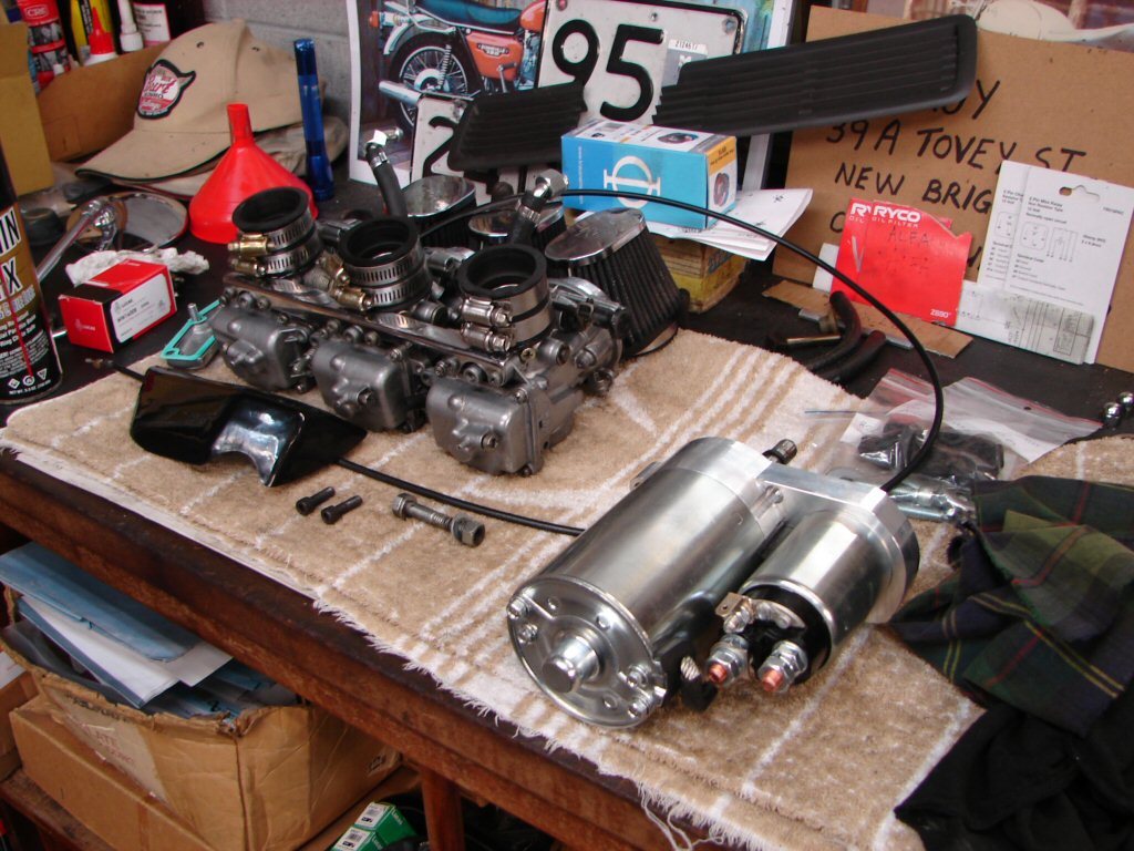
I wiill have to say, that it was a much quicker job to remove these parts than it was to put them in place, because now I know exactly how it all mates up and in what order, so it was a much less dramatic process than I feared it might be.
However, it is still a gross step in the wrong direction at this stage of the game. One tends to assume that a new $1000 starter might work straight out of the box rather than need an immediate rebuild.
Bugger.!
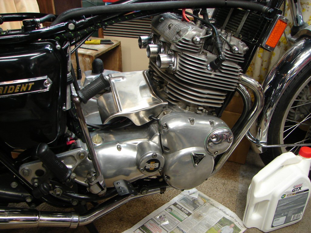
I emailed Dave Madigan - the originator of this electric start assembly - regarding how to reverse the rotation of the motor, having posted the question on the 'Triplesonline' forum. He emailed back promptly with a PDF file giving clear instructions and photos of how to move the internal magnets around a bit.
As it happened, this motor appeared to differ in construction from the one in the PDF, so I emailed him again to make sure I did not cause any grief prising it apart. Things always feel more difficult the first time you have operated on them and the motor was reluctant to come apart the way I thought it should.
Always more to learn...
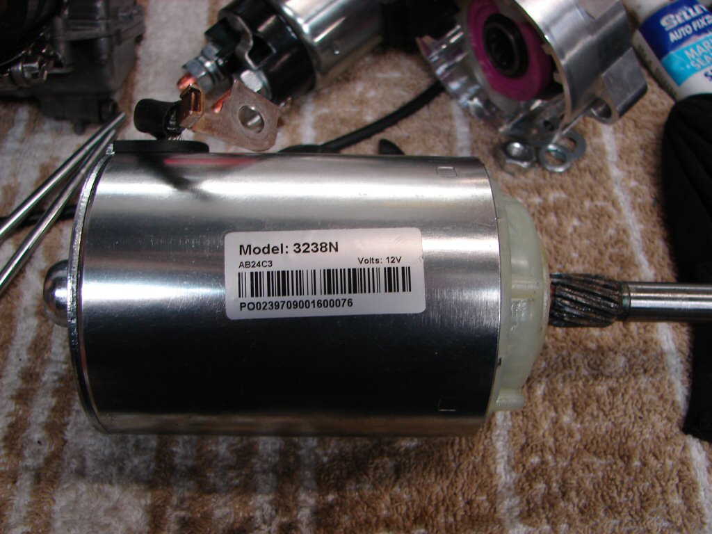
There was one potential issue when dismantling that was to be avoided, which was allowing the rotor to pull out of the brushes, as they would be difficult to reassemble without a necessary tool, so I was keen to avoid this.
A mate called round to enlist my help with an electronic ignition, and we looked at the motor together. I told him why I was being overly careful, and as he was inspecting it he pulled on the brush end of the case and it came off straight away, allowing the brushes to extend into the space that the commutator had just vacated.
Bugger.!
Oh well - now it was apart the reduction gears and their housing pulled off the other end easily and suddenly it was apart. Better still, now the brushes were exposed I could see a way that I should be able to compress their springs and get the thing back together, so it was not so scary after all.
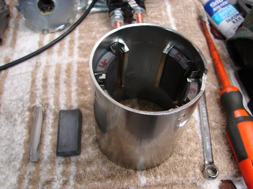
So here we are moving the six magnets one space clockwise at a time, keeping their sequence to each other thanks to the fact that they are all hand numbered. Perhaps all these motors are assembled thus to make it easier for the rotation to be reversed. The magnets alternate between having north and south poles at one end, so moving them only one space alters the entire magnetic relationship to the rotor.
Cool trick.
The brushes needed to be pulled back against their springs in order to get the commutator back between them all. They have a heavy braided copper lead at their base which feeds the heavy current to the rotor, and by placing a small cable tie on each one I was able to pull them backwards two at a time with the rotor poised above it, and very quickly it dropped in under its own weight. Brilliant.
The rest of the reassembly was no trouble and I applied a bit more grease to all the running surfaces.
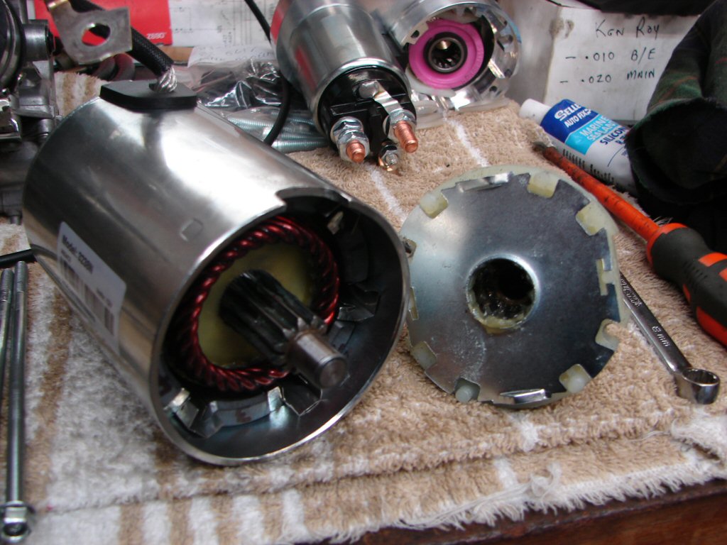
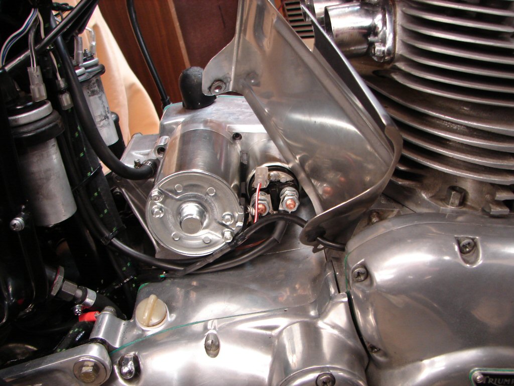
The unit was bolted back into its cosy home as soon as I got the chance, and it all complied without argument. Once again - when you have already done something before, you already know what the problem areas are and have devised a way to avoid them.
I reconnected the wires but decided that - as an insurance policy - I would not refit the carbs until I knew all was well.
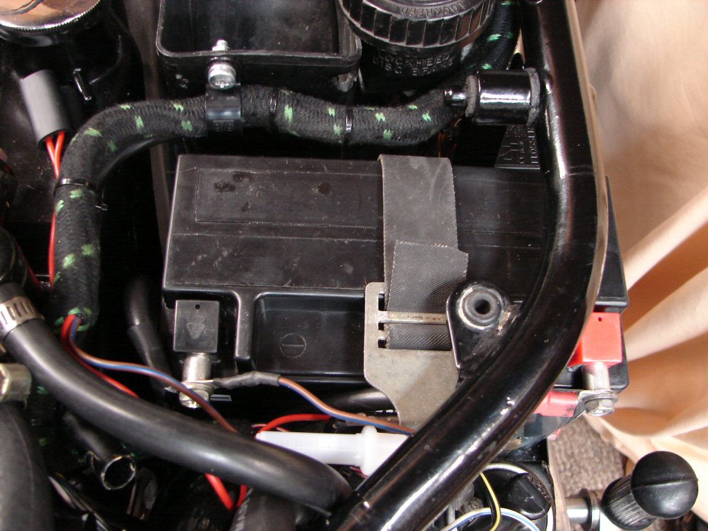
The battery had been removed before I took the starter out, so when looking at refitting it I decided to adopt the same method of connecting it at both terminals, and made up two spacers from tinned copper tube to do the job, as they will give the best conductivity.
This also allows the terminal covers that came with the battery to stay in place, which might prevent any accidental shorting out when using tools in the underseat area. It also makes it very clear which are positive and negative.
The fact that the earth terminal is easiest to get to behind the sidecover allows the safest way to disconnect or reconnect the battery, as the earth cannot short to the frame, and once it is disconnected, nor can the negative terminal.
None of this is accidental...
Of course, with the battery in place it was time to give the starter the acid test. I left the spark plugs out to make its life easier first time around, but I get the impression that it is not going to bother it unduly.
It whizzes the engine over at a brisk pace making it sound effortless, and gives every indication that it might serve to supply an every-time button start.
I am impressed, having never seen a T160 starter manage as easily as this does - plugs in or out...
So the tank and seat went on and the spark plugs went in, and now the bike sits with its exhaust facing the door awaiting the occasion of the first start.
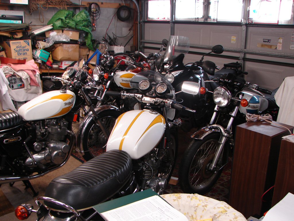
Of course, the obligatory fuel leak test will be made before the start, but as that is done outdoors the bike is as complete as it could be otherwise.
Play has been stalled as the other bike - which I thought would be the easiest to get running - proceeded to have the most puzzling carb flooding issues, which was finally traced to manufacturing dimensional problems which were able to be addressed. A sad reflection on today's quality control or lack of it. Anyway, today the other bike fired up at last, so we can soon attempt the first start on this one.
Exciting times.!
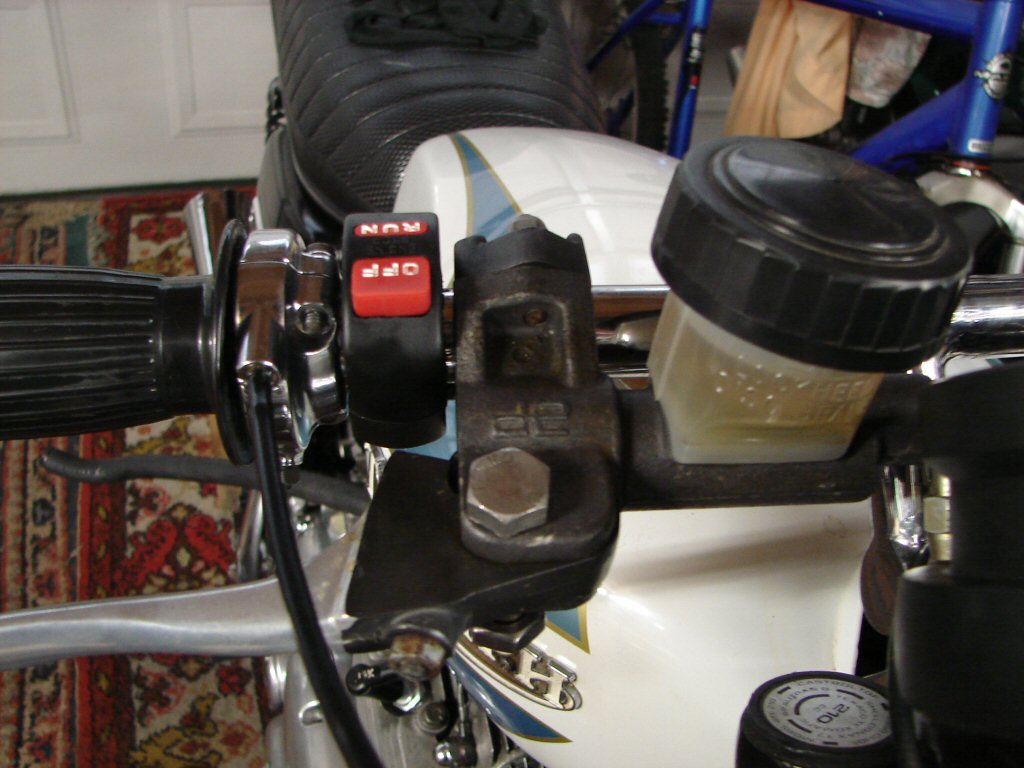
Well - not quite the exciting news I was hoping, but things can only be dealt with in the order they crop up. I was moving the bikes around in the shed so that this one could be in the centre spot for test running.
During the manhandling I got a wet finger, and soon traced it to brake fluid leaking from underneath the AP Lockheed racing front brake cylinder.
When life is pushing back from every direction you have to learn new skills. I guess it is a form of emotional detachment. I don't even swear any more - it just seems too pathetic..
I thought I had gotten away with the cleanup of the front cylinder, and it bled up fine and works fine, and I am not sure I can even detect a drop in the fluid level, but its leaking for sure and I do not wish to send it home with something still not right.
We have come a long way together this bike and me, and I refuse to surrender..!
I am currently trying to find out if the seals within this thing are by any remote chance the same as a stock Girling cylinder, as I have a repair kit for that, and the only repair kits for this one are in the UK and at a hideous price.
But..
It ain't gonna stop me trying to fire it up. So there.
So - rather than slow progress by stripping the front master cylinder - I decided that as we do have a working front brake, I should get the bike running first, because I will not be able to run it long enough to get it hot enough to warrant a head tighten, and am not au fait with tuning Mikunis, so will be best to test ride it to both get the oil warm enough to drop it, then read the spark plugs to see how even the three cylinders are tuned.
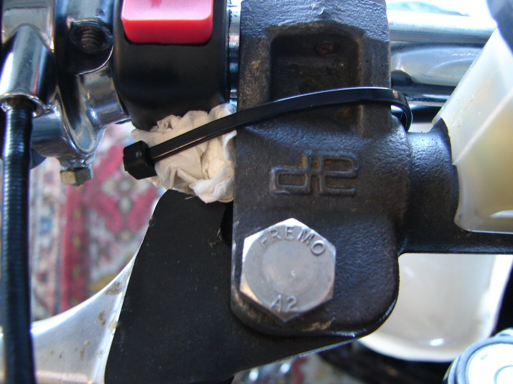
To that end I fashioned the Kilroy front AP Lockheed leak stopper..
Yesterday I prepared for the first attempt at starting the sleeping beast. First I turned on both fuel taps and waited for some time, no drips anywhere but I couldn't tell if the carb bowls had filled, so I used their built-in drain screws and sure enough they all held fuel.
That seemed to be the last step, so I set the video recording and walked over to the bike, leaning to reach the choke on the far side. It wouldn't pull out. It did move slightly but something was trying to pull it back. Stopped the video and got a torch to peer under the tank and discovered that the centre choke was fouling the new fuel line.
Whipped the fuel tank off to get to grips with the choke setup, which is a long rod with three small brackets locked to it that pull the choke mechanisms on each carb. The right and centre brackets were retained by screws with quite large heads, whereas the left side had a shorter screw with a much smaller head. Maybe if that one was in the centre it would create more clearance.
So I dismantled the rod assembly and swapped the screws then refitted the tank, keeping the left side fuel line where it had to be, and now everything was behaving again. You don't know until you try it I guess.
I did not get another chance until today, so with a space cleared I started again. Camera rolling, fuel taps on, choke on, key on, killswitch to run.
Well brace yourself, because what took place is captured here
After that the return oil line got connected back to the tank and the tank oil topped up.
Because I don't leave many things to chance I poured some of the bled off oil into a clear jug so I could have a look at it, and just like the other T160 I fired up for the first time the other day the oil had discoloured immediately. I blame this mostly on the oil cooler, as it is a 'dead' cavity and not self-draining, but having spent a considerable time on both oil coolers flushing them out there was still oil and probably carbon residues that had resisted leaving.
Unlike the other bike, this oil was very frothy, indicating that the crankcases had emptied and the scavenge system was now sucking oil and air together. This is what it looks like when you bleed the cooler after doing a regular oil change, as you usually run the motor to warm it up before draining and flushing so the crankcase is mostly empty to begin with, but when you have just filled it with new oil, the frothy oil is clear and new.
This don't look very new..
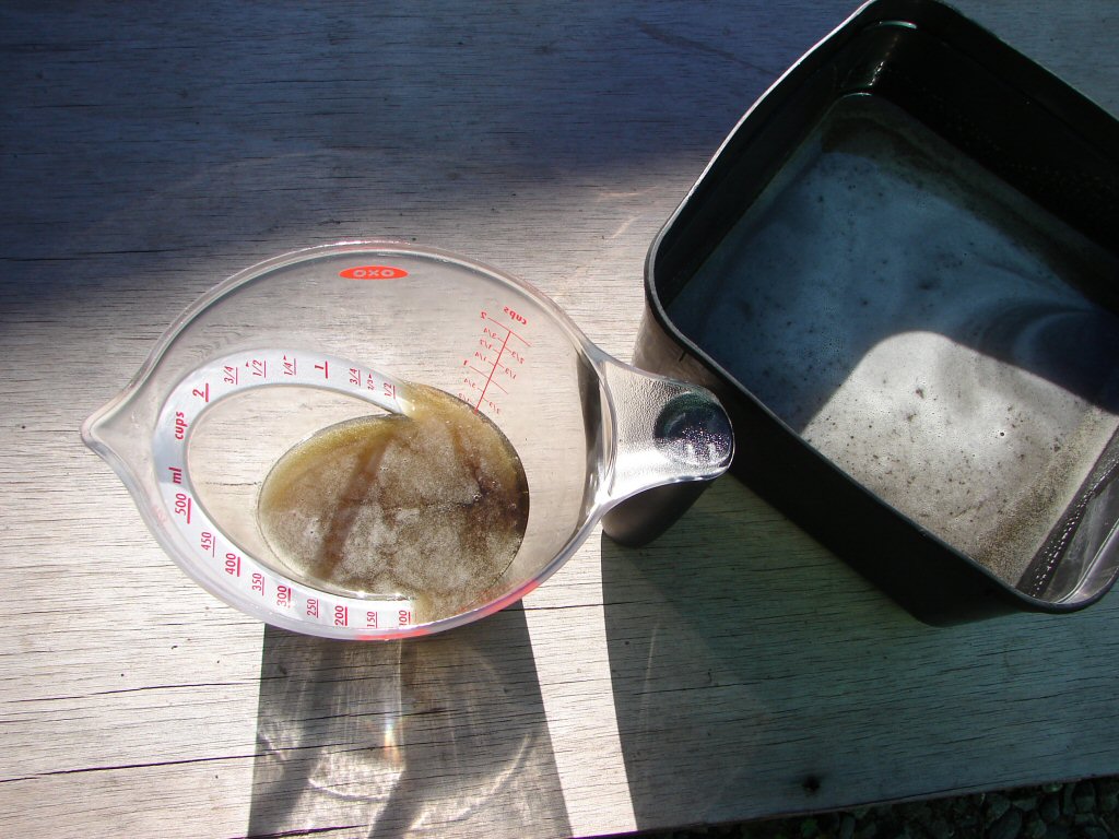
Of course, this is exactly why we sacrifice some oil, to prevent it from returning to the system. I drained the main container to check for any solids, and while there were tiny specs of shiny I could not feel them, like tiny flakes. The oil tank and sump and their filters will be checked when all this oil gets dumped after the first test ride. It is the only way to eliminate anything foreign at all before it lodges somewhere.
This amount of caution is only necessary because both bikes suffered mechanical failures inside their engines, and there are so many places for grit to hide.
The final step today would be to check the ignition timing, as the carbs seem happy enough to stand a test ride and show me via the spark plugs what I need to know.
So here was the bike with the strobe hooked up waiting for its second brief run..
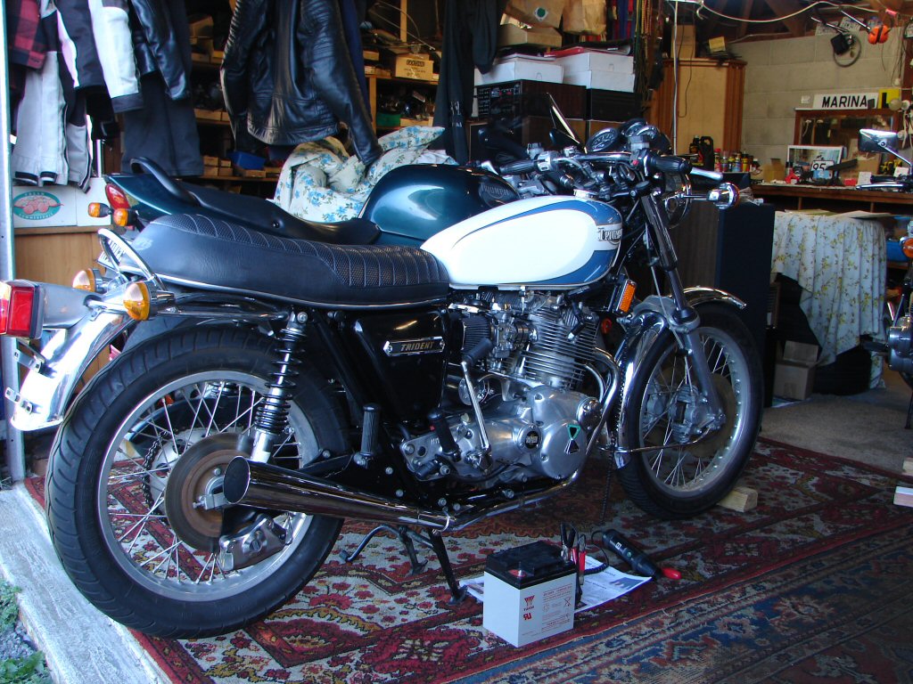
I was really pleased when the timing proved to be spot-on, and no doubt this helped to provide the result we got today.
Another step closer..
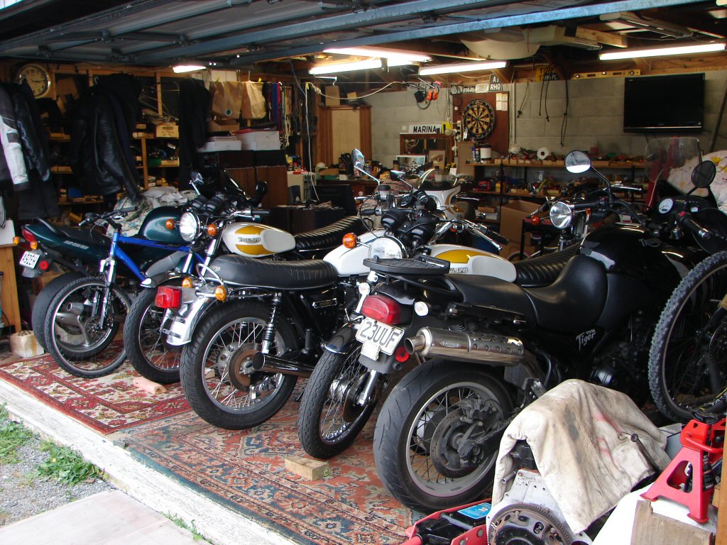
Currently awaiting weather in which to test ride 3 T160's so the shed has been rearranged to put the imminent rides on the front row of the grid.
I doubt that I have previously had a more desirable seven triples in the shed together, especially with four being T160's...
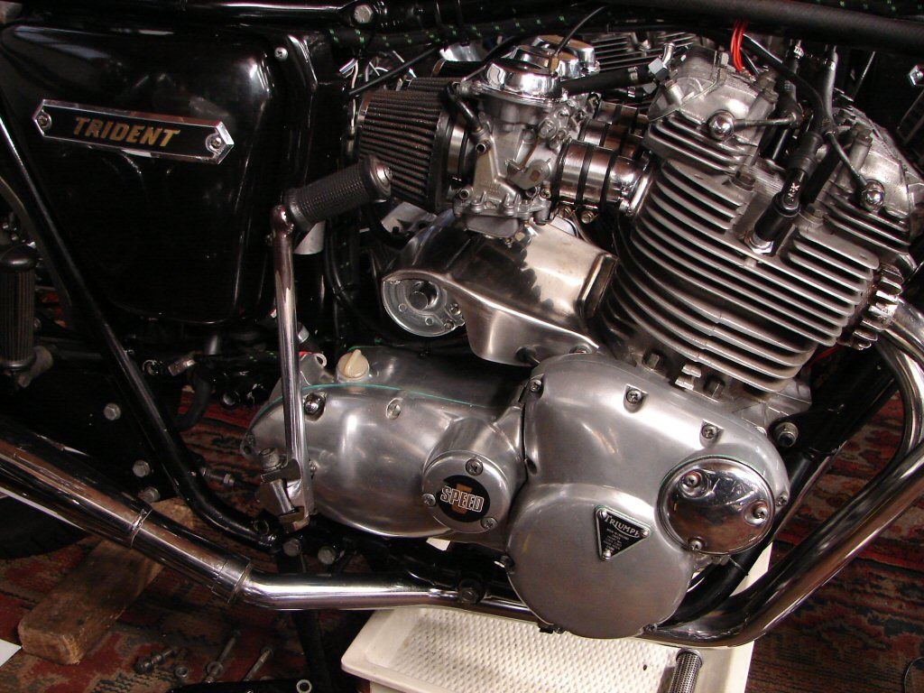
The test ride.
The bike started as easily as it has thus far, and even though cold it only wanted the choke for a brief warmup. Heading down our street it was obvious that the motor was keen to respond instantly to the throttle - which has extremely light return springs - and decelerated almost as abruptly. Oil pressure magnificent for the brief jaunt, which was mostly to warm up engine and oil prior to dumping this lot as a final flush of all reservoirs except the gearbox.
In the couple of miles the carb tuning appeared to be just as you would want it, although I have not yet sighted the spark plugs for a more intimate gauge of things. I would have to say that the engine was just brilliant for first time out.
Unfortunately the riding experience was at the other end of the scale.
The front brake was scary fierce and I locked it up twice just as coming to a stop.
The speedo and the neutral light were neither working.
The clutch is fine in use, but the cable is too short so it does not take up until the lever is really well out. All the cable adjusters are at minimum, but the cable inner is not long enough for some reason. I checked three other cables I have on hand but this one already has the longest inner of them all.
The gear selection has a major problem in that it finds false neutrals and skips from 3rd to 5th gear. I did not have the gearlever set for my boots and it feels a bit like there is some lost motion as the rearset lever travel is a lot more than expected. I wonder if the neutral light switch could be causing any of this and will back it right off.
The sidestand has to be folded right in under the exhaust, as it has been bent down so far it would be a grounding hazard otherwise. The reason it has been bent is because the frame lug is bent up, so there are two problems really.
Despite having angled the rear wheel to the right the 18" tyre is rubbing on both upper and lower runs of the rear chain. I am afraid that the tyre is simply too wide without going to great lengths with narrow chain and sprockets, but probably the 18" rear tyre that was fitted to the X75 Hurricanes would be of similar diameter but might not cause the same interference issues. I will ask someone for a measurement to find out.
So despite my hopes for a fairytale debut there is more work to be done.
So today I drained all the oils and found nothing to be alarmed about as far as any foreign material goes. I also checked the head bolts and they tensioned to pretty much exactly where they set to during assembly. I will check them once again before the bike leaves as they only got a brief heat up this ride.
Great promise but more problems to sort out, so I guess I am a tad disappointed - mostly as I couldn't really give the motor a few revs as the higher gears were difficult to find.
Two steps forward - several steps back...
I was able to get an improvement in the clutch cable issue by slightly shortening the handlebar housing where the cable adjuster fits in. This is a T150 lever made of alloy, and it is longer than a T160 lever where the adjuster fits, so a tiny reduction in dimension gave me the improvement I needed to get the lever behaviour desired.
Then after removing the rearsets and engine mounting plate the gearbox came apart. I removed all the gears and selectors just to ensure that they were assembled as per the book, and they were. The only thing that was not right was that the kickstart ratchet end piece was so tight on the mainshaft that I had to use a puller to remove it. The thin nut on this assembly has to be tightened to 40ft.lb so that may excuse a bit of deforming. I cleaned up the splines inside and out with a small square file so that life would be easier for it in future.
It all went back together and I was able to select all gears by moving the quadrant up and down one position at a time while moving the rear wheel to and fro - as the clutch was still attached in the primary I could only rotate the rear wheel by holding the clutch lever in at the same time. All appeared to work normally.
The outer case went back on for a trial fit after I had done all I could to improve the freedom of movement to the rearset gearchange setup on the primary side. I now found that I could engage first and second gears and find neutral ok, but once moving to the higher gears the selectors began to misbehave as they had on the test ride. Now I was doing it by hand and was close to the gearbox I could hear that the plungers in the selector quadrant were losing engagement with the camplate quadrant in the higher gears. So the outer cover came off again. Now that the plungers have been removed I can feel wear on their teeth, but not detect any wear on the teeth of the quadrant, so hopefully a new pair of plungers will rectify the problem. As the extra linkages of the rearsets create more friction in the setup, the gearlever does not return to the centre position easily, so the plungers do not always engage for the next gear until you assist the gearlever to return with your foot, so I will replace both the plunger springs and the centring springs to make sure we have the best chance of a complete cure.
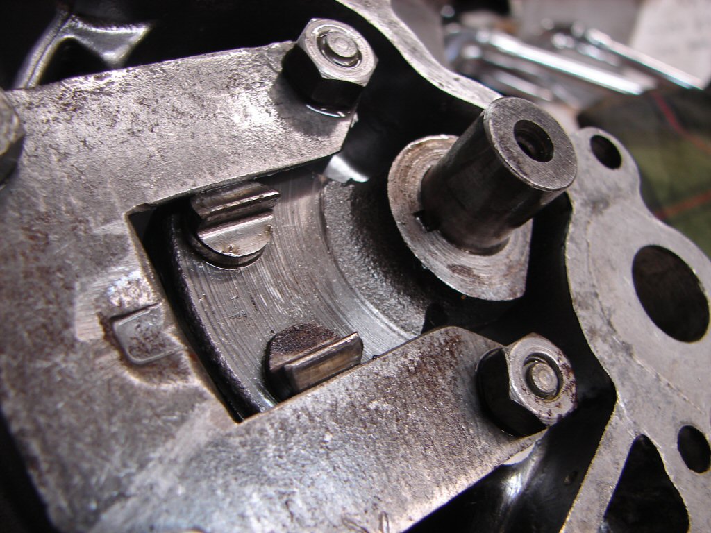
Obviously the wear that is seemingly causing the problem did not occur while the parts were all in storage, so this condition could hardly have escaped being present in some form when the bike was last in service. This is why bikes "in boxes" are twice the work during rebuilds, because such information is not passed on and will only come to light once the whole thing is back together and attempts are made to operate it.
Of course, 'new' parts can be as much of a problem as the old parts were.
The 'new' neutral light switch got modified as the design has changed and the large blade terminals on the new style have to be bent in order to even get the thing in place, and this had resulted in a loose internal connection, so I cut the blades off and soldered the two short wires directly to the rivets that go inside. That is now working again but will need re-adjusting when hot to keep it doing so reliably.
The speedo problem is not fully diagnosed yet. I pulled the inner cable out and it is complete, which means that either the drive unit on the rear axle or the speedo itself are the problem - or the fit of the cable to either of those parts. When I fully inserted the inner cable from the top I was still able to twirl it around, so the problem looks like the drive end.
That figures.
I was really hoping that removing the rear wheel was not going to become yet another port of call..
Thanks to their proximity the parts people had my bits delivered today and they were promptly installed in the outer cover. While it is not too obvious in the previous photo, the two plungers are not equally extended, as the rest position of the quadrant is not dead centre where I think it probably should be. The reason is that the machining of the case itself has left an abutment in the centre against which the inner ends of the springs rest, and the abutment is off centre. It has presumably always been like this so hopefully it will work normally now that the plungers have a better purchase.
As you might suspect, my use of the word 'hopeful' means I am not yet convinced..
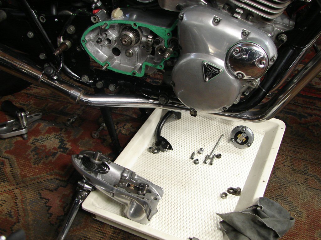
Nothing for it but to put the cover back on, and I found I was able to select all gears albeit with some difficulty around the centring of the gearlever. The new springs seemed to be stronger but I doubt that the difference will be noticeable until the engine is running. It is never easy to change gears at rest, and more so with the clutch still playing a part.
Last job today was to remove the speedo cable from the drive unit, which turned out to have no innards, so I guess that failed some time back. Will see if a new one exists.
Rather than pull the mufflers off to release the rear axle I dropped the rear shocks out of the frame and let the wheel sit on the ground. It only needed to roll back an inch or two for the speedo drive to be removed.
Well Holmes - I think we have found a clue...
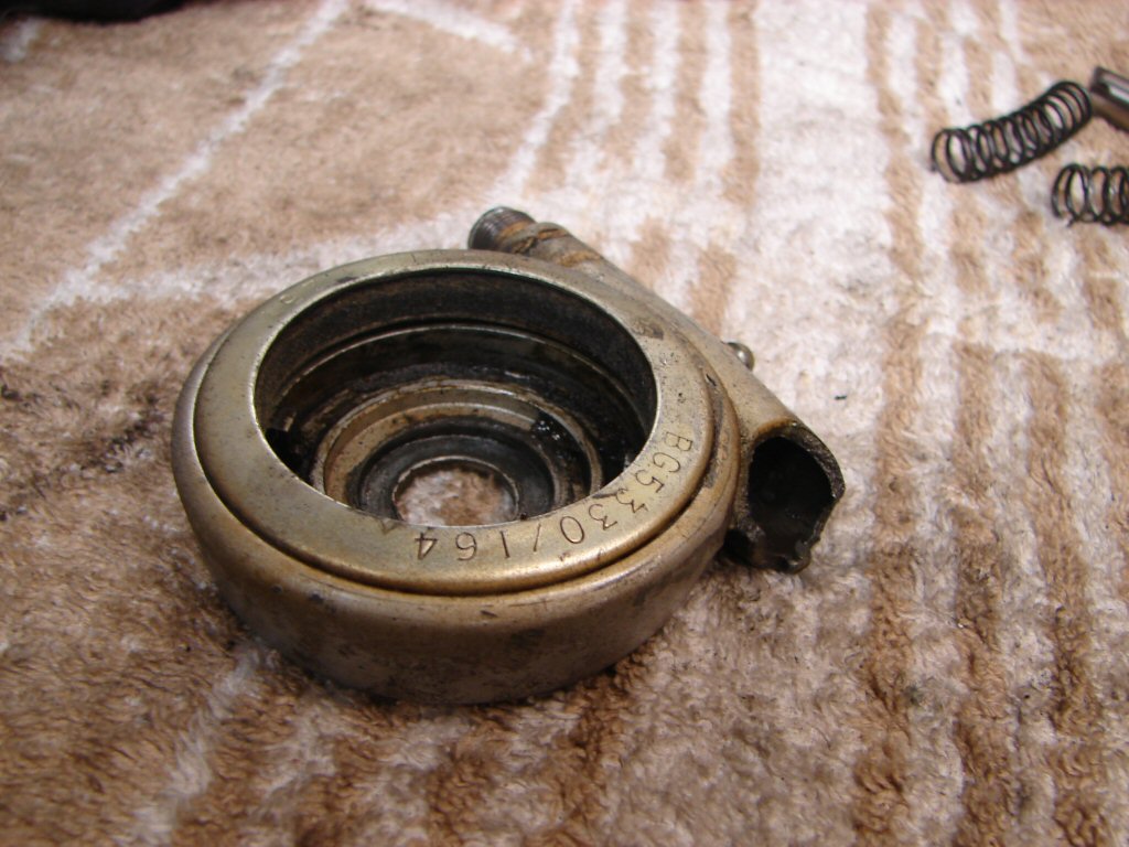
Difficult to know what causes this kind of failure, although I will certainly be checking that the speedo rotates freely. The cable is intact and I had oiled/greased it when the instruments were off the bike, but most speedo drives would never receive any lube during their service life - despite the grease nipple.
The new speedo drive turned up, and as the latest offerings now feature a slightly larger hole for the axle I trial fitted it on the wheel to make sure everything got along with everything else.
Fortunately it seems to do just that..
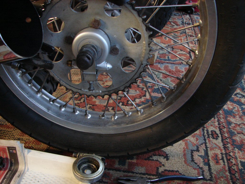
That led to the proper fitting and getting the wheel back in place, which is always a gritty manoeuvre even without an oversize tyre getting in on the act. Actually, the chain joining link was the fly in the ointment, and had been on the way out. Turns out that the joining plate that is held by the retaining clip is twice the usual thickness, so it took some convincing to behave.
I took some time to try and find an alignment that would allow the rear tyre and chain to rotate freely without anything rubbing, and I finally did. Then the speedo cable nut decided to be hard to fit in that it tightened up on the threads before reaching home. It was also tight on the broken drive, so it seems that the cable is the offender. With a few on and offs and some lube it finally went all the way and the cable could be felt to turn up front when I spun the wheel. Great.
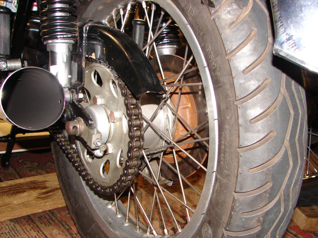
While mating the cable to the speedo the speedo lamp fell out and the bulb was all black, so I replaced it with an LED which I now use as they actually make it possible to read the speedo at night.
The next port of call was the rearset linkage which seems to be a bit resistant to moving freely. I found that the pedal was binding slightly due to side preload from the footpeg mount, so I dressed the two sides of the alloy lever and oiled it again on the way back together and it is as free as it has yet been.
One of the two rose joints on the rod that connects to the actual gearlever shaft also felt a bit sticky, and that was a mystery at first. The two rose joints have small flat washers between the joints and the mating surfaces, and one washer was hard to remove. It turned out to be an alloy washer and it had deformed and was limiting the amount of swivel the joint could manage. I faced the washer with a file, but will try and find a similar sized steel washer as the alloy one will deform again for sure.
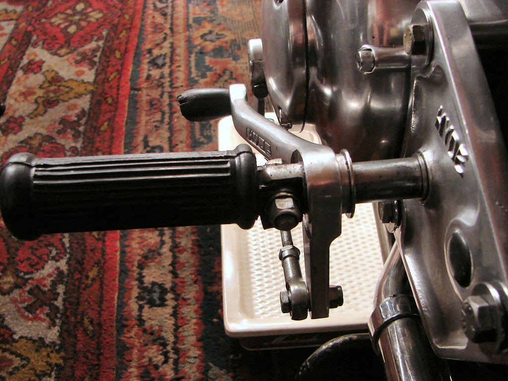
Final move today was to refill the gearbox oil, and I left the drip tray underneath for the night so any leaks will be obvious should they even think about it...
There were no drips from the gearbox, so the primary drive and oil tank were refilled. Despite fitting the steel washer to the rearset linkage the gearlever still felt like it was moving too far without doing anything. However, I could at least select all gears by use of the lever, but the action felt vague when compared to a standard setup which was just behind me. I decided to remove the rearset linkage and try fitting a standard gearlever, and that felt better, but the main problem felt as if the gearlever was not returning to its centre position after selecting a gear, so the next selection did nothing unless the gearlever was physically moved to the rest position first.
Nothing like an acid test, so after restoring the rearset I rode the bike around a few blocks, but while it seemed better it was still not anything like it should be. It feels like a set of mismatched parts trying to get along together. At least the speedo works and the front brake is a bit more controllable having reset it to the factory lever adjustment. The clutch is also greatly improved, so we are down to mostly one problem.
Having said that, a most unbelievable new problem was now apparent. Honestly - this bike has an endless repertoire of weird issues, but this one I have never experienced before. During the ride the bike would come to rest idling way too high. If I took my hand off the throttle it would return to normal idle. When I got back I watched the throttle action on the carbs as I rolled the throttle back to the stop. The carb linkage smoothly returned to idle then began to rise again as I reached the stop. Basically, moving the twistgrip in either direction from rest increases the throttle.
WTF..!
The twistgrip came apart and the problem was the stop - which is part of the adjustable friction mechanism - but it was sitting further back than the cable wanted it to be, so was going over centre when deliberately shutting the throttle until it went no further. I have never seen anything like this before, but I doubt it will be the last event that makes no apparent sense...
I have drained the primary and will remove the outer cover to ascertain whether the selection problem begins in the crossover gear shaft mechanism or inside the gearbox. I had a day off today to try and get my mojo back...
A point of note though.
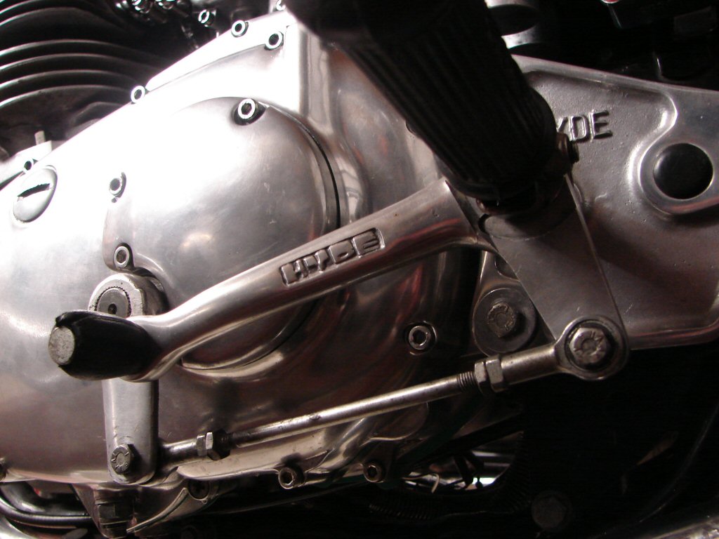
Looking at the rearset linkage in the above photo you can see that the gearlever and linkages look nicely made, while the arm from the gearlever shaft looks decidedly home grown. It appears to be from a gearlever of some sort, shortened and rounded at the bottom with a hole drilled through it, plus it is angled outwards which stops it being parallel with the pedal end of the linkage. Hardly in keeping with the obvious quality of the rest of the setup.
Once again, it all came in boxes and I have had no experience of a Hyde setup before now, but I sense a rodent behind some of these inconsistencies.
Tomorrow the battle resumes.
Today the primary cover came off and I removed the small quadrant off the gear lever cross shaft so that I could remove the sleeve/spacer and release the shaft. This had to be done in order to draw the shaft out of the link at the gearbox end so that I could try selecting gears at the gearbox end, which would inform me as to whether the problem was in the gearbox or the cross shaft assembly. It did not take long to confirm that the problem was not inside the gearbox. That is good news to me - been there done that too often already.
The shaft turned freely without anything on either end, and the link in the gearbox outer cover - while a bit corroded - was working as it should. I decided to remove the shaft and the bits from inside the primary and put them on the bench, as whatever was going on had eluded my scrutiny thus far.
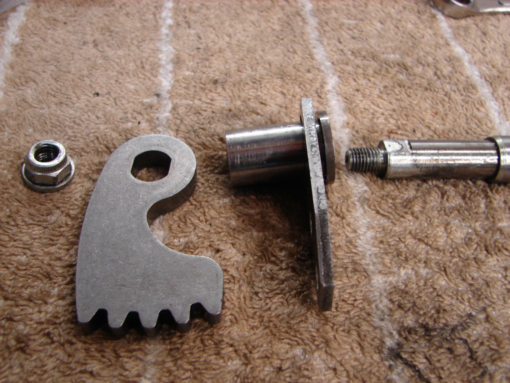
The sleeve limits the end float of the shaft and is held by the retaining plate which bolts to the inner primary case. There is another tubular spacer which fits over the outside of the sleeve. The quadrant then fits over the two flats on the shaft and is held by the nut and washer, and you tighten the nut convincingly or else the quadrant gradually wears the flats and then you have a sloppy gearlever action.
Last night I observed that ".. it feels like a mismatched set of parts.." and it seems to me I was on the money. I cannot see this assembly being able to work - at least as I think it should - using this set of parts, and as the owner rode the bike to the place where it was stripped 16 odd years ago, and says that the gear selection was perfectly good at that time, then something has changed between then and now.
The set of parts here do not fit together in the way I understand they should, but without pulling a cover off another one I can't entirely confirm my suspicions as the manual does not describe what each part does. What I do know is that it doesn't work the way it is.
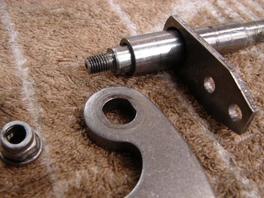
As the sleeve butts up against the boss on the shaft as you see it sitting here, then tightening the quadrant has the effect of locking the whole assembly together, as the sleeve prevents the quadrant from reaching the shoulders of the flats on the shaft. You can see that the sleeve has been bearing directly against the quadrant in a convincing fashion. If my memory serves me at all, this arrangement should be fully floating, and yet this one is anything but.
My suspicion is that one or more of these parts have been swapped out with others whose dimensions differ, and that this is the first time they have all been fitted together, as I can't see how they could have ever worked before as they are now.
I am in the process of researching the proper dimensions of the individual parts before I make any irreversible modifications.
Another day - same mystery.
I had another quadrant on hand which I think came off my T160 as it had exhibited the beginnings of some free play. I can see from the wear marks on it that it had been tightening against the shoulders of the flat on the cross shaft, which made me think this assembly was wrong.
After all manner of faffing about today I have still not found the real problem, but I can also see that the spare quadrant appears to have been pressed against the sleeve, so maybe it is only the outer spacer which is supposed to rotate freely. This is designed to keep the quadrant in its correct position within the primary case.
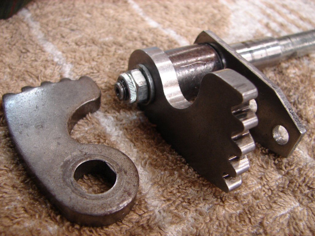
Jury is still out...
I was beginning to doubt all sorts of things I had already done up to now as I was simply unable to explain what was happening. From the first test ride it had seemed that the gear selector setup was failing to return to centre between gear changes, and therefore wouldn't. Then I found the wear on the selector plungers and tended towards them failing to maintain their grip seeing as how their teeth were blunted. I bought new return springs in case those fitted had lost their tension, but when I had it all apart it turned out that the fitted springs were slightly bigger in diameter and definitely stronger than the new items, so I left them in. It is not unusual by any means that replacement parts are not quite made to the same specs as the originals after all.
Then I turned my attention to the remote gearchange bits - both the stock left side change and the rearsets - but although I thought I had found problems they got ruled out with the next set of checks. It looked like we were back to pulling the gearbox apart yet again, so I did that.
Throughout this process I had always been able to select all gears by moving the quadrant inside the outer gearbox cover, so I was confident that the insides of the gearbox were all doing what they should. The problem was obviously to do with the parts in the outer cover, so that came off today and I started again.
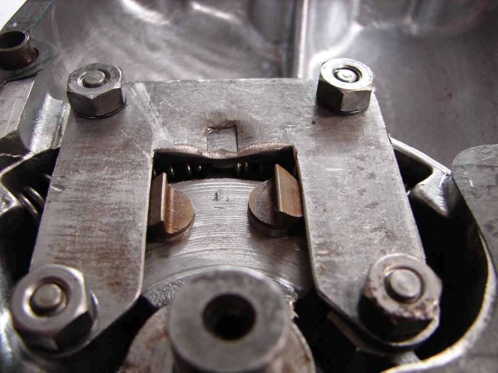
The plungers are uneven in their amount of extension and I suspected that perhaps the machining of the case itself was off, but something else alerted me again. I had fitted the cross shaft and set the gearlever foot to its correct position in the primary, then ran a marker pen along the side of it on the rear primary sprocket. I then made a parallel mark 1/4" further out which would allow me to check the mesh of the two quadrant "feet" inside the primary that mesh the gearlever to the cross shaft, as there is a small hole through which you can set the position of the gearlever half.
I trial fitted the outer gearbox cover back on and attempted changing gears by using a spanner on the far end of the cross shaft, but the gear changes were still off. Then I noticed that the cross shaft foot was now further away from the marker pen line, so it was definitely not returning to centre. Something was binding. Cover off again and I made a number of tests of the selector and plungers. I had noted that there was wear on the plate where the plungers get depressed so perhaps I should clean up the tapered edges that perform that task.
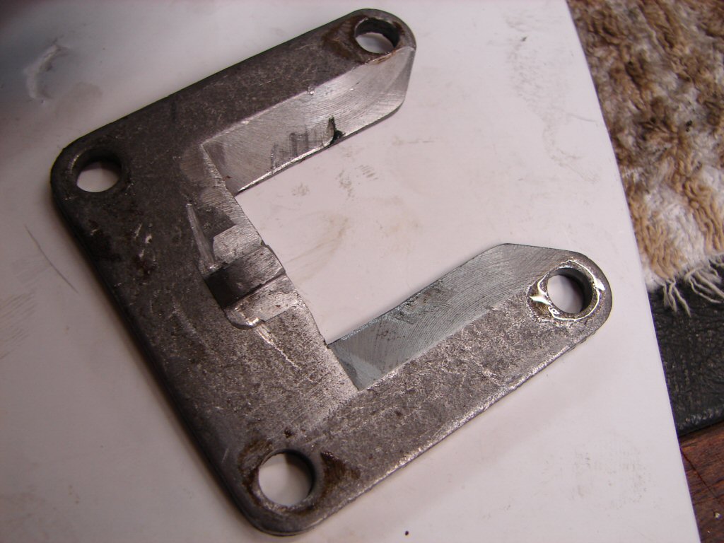
Then I had a 'WTF' moment.
There are curved scratches either side of centre on the underside of the plate - what could have caused that..?
You can see in the last pic that the return springs rest against the centre stop of this plate and the selector quadrant compresses each one in the direction it moves. The only thing that can scratch the plate are the springs themselves.
The springs came out - and I think we have the answer. It was not the new springs being undersize that was a problem - the fitted ones are too bloody big. I think we may have found the problem dammit. Here are the new springs in place, and besides sitting lower in the case they feel more compliant and there is clearance between them and the plate along the full range of travel...
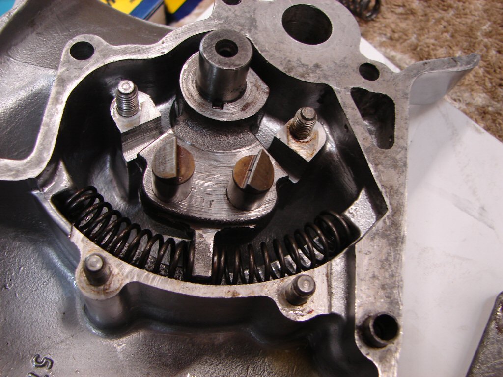
Even better, it appears that the two plungers are now going to sit evenly, so everything is leaning in the right direction for a change. About bloody time..!
I think the old springs are the mismatched parts I was looking for - they do not belong in here - and because this outer cover was completely assembled when it arrived I had assumed it was still as it had been when removed from the bike.
Now we know it was not...
So here we are with what will hopefully prove to be the final configuration. I did slightly dress the edges of the tapers which compress the plunger springs and the movement of the assembled article feels far more positive and compliant than it has until now.
I always think that it should have been more apparent earlier on where the problem was, but it wasn't, and there were plenty of other suspects, so it played out as it did. On some level it feels like it was sabotage, therefore looking for natural causes does not produce results as quickly as it might otherwise.
Whatever - I will be very happy if it just bloody works now...
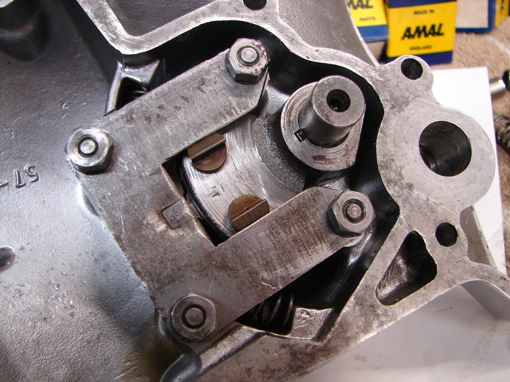
The test ride looked promising, as upchanging into second was precise, and as I progressed I was able to select third and fourth fine. Dandy. Then I went to change down and couldn't. The gearlever just felt like it was traveling a long way without doing anything. Fishing around and lifting the lever without trying to change up seemed to help something engage and I ended up back in second, so I pretty much stayed there for the ride back home. When I had stopped I tried selecting while the engine was still running but it was not making sense at all.
I had to wonder if it was the warming up of the powerplant that was causing some dimension to alter enough to queer things, but it is always guesswork until you start ripping bits off and looking. So today the rearsets came off and the gearbox oil got drained yet again.
I will take the outer cover off the gearbox a fraction to disengage the cross shaft and see if I can still find all gears by moving the selector quadrant with a socket wrench. If so then the problem is still in the plunger/return spring area. It does feel like there is too much resistance to free travel, although after fitting the new return springs it had felt great - it only seems to go wrong when everything is all bolted up. The battle is not yet won.
Biscuits..!
One thing I have found having removed only the small round plate which covers the gearbox end of the cross shaft is that there is some lost movement between the gearlever and the selector quadrant. That can only be the small quadrant on the primary end of the cross shaft moving on the flats, which was the first port of call last time. Will see if I can shim it or deform the internal flats of the quadrant to close up the tolerance. It will need to be made pretty secure though - quite a lot of torque transfers through it.
In other news - we have located another T160 outer cover complete with selector parts other than plungers - which we have - so maybe a complete swap would be the fastest way of proving where the trouble definitely is...
Today the gearbox cover came off and went back on the bench. I checked the fit of the plungers in the quadrant and used a large drill bit to make sure there were no burrs around the holes they sit in. I filed and emeried the tapers of the plate that pushes the plungers down, and also the mating surfaces of the plungers as they had some machining marks. I then fitted the plungers one at a time and checked that they released smoothly.
The changing down plunger did the weirdest thing. It rotated as it moved down its ramp, and came to rest on a diagonal. Whether this could actually prevent it from engaging with the gearchanging quadrant under running conditions I know not, but it turned out to have a sharp corner at the edge of the tooth which was causing it to do this, so that got smoothed off.
I have trouble believing this kind of shit actually...
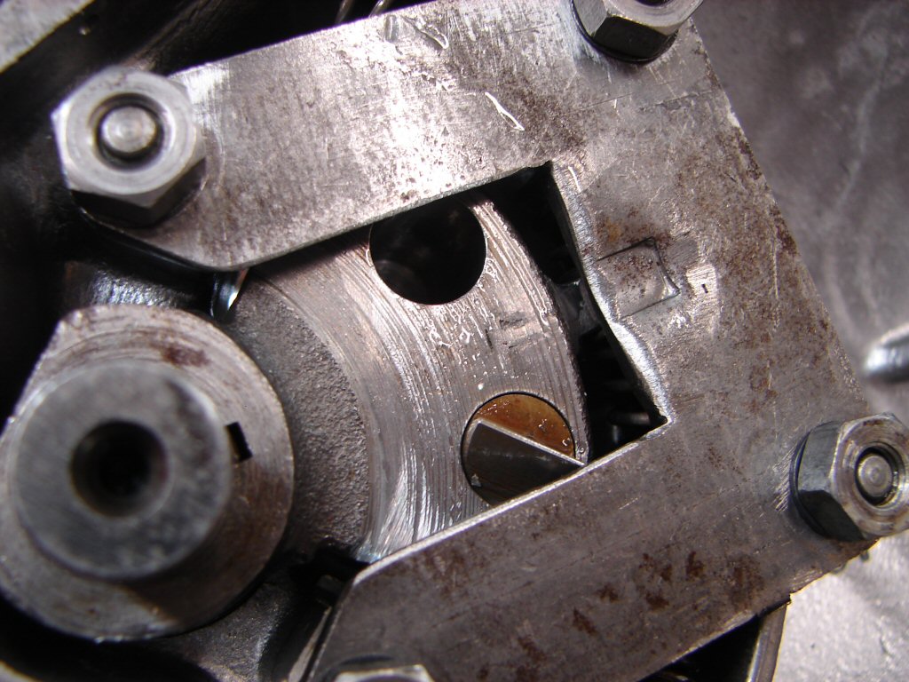
After all that everything got cleaned up, oiled and put back together, and the cover went back on the gearbox. Once the oil goes back in it will be possible to ride it at least far enough to see if all gears are accessible.
If not it will be time to try another cover...
After numerous days of rain I was finally able to test the gearchange. I had found that I could engage all gears via the gearlever while the bike was at rest, with a bit of wheel turning to facilitate the complete changes, and in both up and down directions.
I thus took it out on the road and found that while I could indeed change all the way to fifth gear, I could not change down, so some time was spent on the roadside, operating the gearlever by hand. The problem was definitely to do with the centring - or in this case 'not' - of the selector quadrant, so the downchange plunger was not engaging with the gearchanging quadrant, and there was just a lot of travel of the lever with no action taking place. You realise just how much control of the bike is dependant on changing gears when they are not readily available.
Time to replace something - so we shall obtain another outer cover which has showed up at a very opportune moment.
Meanwhile it has become obvious that the throttle operation is still ropey, and having engine revs rise unexpectedly when the throttle is closed is another hazard that needs more work to cure. The twistgrip failed to respond to treatment, but also the throttle cable itself has damage at the twistgrip end, and something at the carb end is fouling the return spring action. The carbs had to come off the bike in order to even see how the cable attaches to the carb linkage.
In order to show that I am not being over dramatic when I observe that everything on this bike has turned into a battle, here is the seized nipple I found after a bit of dismantling. As the cable has been forced to bend each time the throttle was used, it has started to fray visibly.
I had to chop the end off the cable to get it out of the way first, then various small arms were employed to make the rest of the culprits surrender..
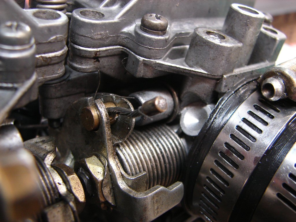
It was difficult in the confined space to try and dislodge the nipple, but having figured that I would rather gnaw my own arm off before disturbing the relationship between the three carbs I persevered until it gave up the fight.
The bracket is as it was from the get-go, so I can see why the nipple was not interested in rotating in use, let alone coming out. Needless to say it got straightened immediately.
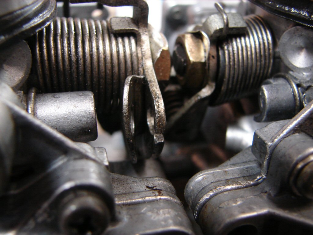
Of course the nipple of the replacement cable was too big to fit in the holes, so that had to be sanded down a number of times to get a workable sliding fit. I finally got it into place and threaded the rest of the cable up to the top of the carb.
Sorted you think - oh no, not this bike...
Neither the new or old cable adjuster threads bear any resemblance to the thread in the alloy housing, so the old adjuster had been forced in, stripping its threads on the way. As this adjuster needs to be locknutted in order to stay put, having a working thread is kinda necessary. I guess I need to find what kind of weird-arse Pongolian thread it is and find a suitable tap.
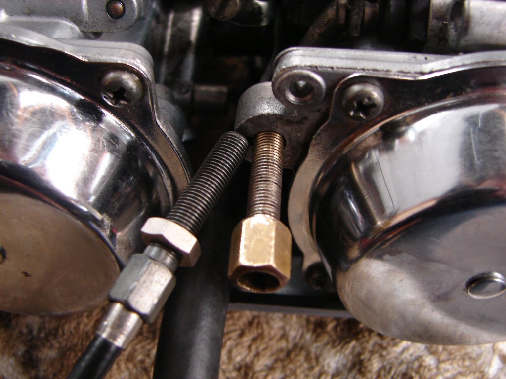
Business as usual then.
Tap located and thread repaired, so the carbs are hopefully ready to be refitted. The return spring action seems to be improved, no doubt a little oil helped, but I suspect that the frayed inner cable has been adding a bit too much friction to the plot. If the return still feels too light I shall add an extra spring to make it feel more business-like.
Today both of the new parts turned up with the same courier. One of these parts looks newer than the other...
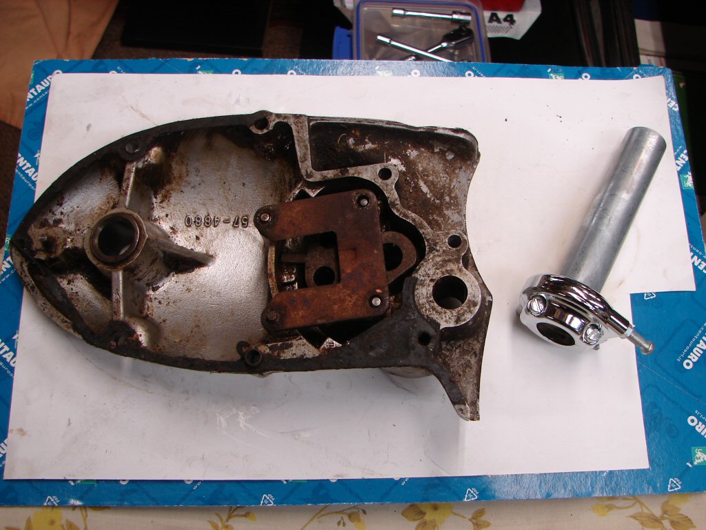
I know we were lucky to find a T160 outer cover at all, but forgive me if I am not convinced that this one marks our salvation just yet. I think I will have to drive the quadrant off the shaft of the current cover and see which of the parts we have are going to work best together.
Its a bitch that the reason for the selecting problems is still not clear, but maybe pulling everything apart that can be will reveal something I have missed once I can compare two different sets of parts.
Today the carbs went back on and then their respective filters. Nice easy setup to remove and refit so that is definitely in their favour. They have behaved impeccably throughout the brief periods of engine running so I have resisted touching anything to do with their state of tune.
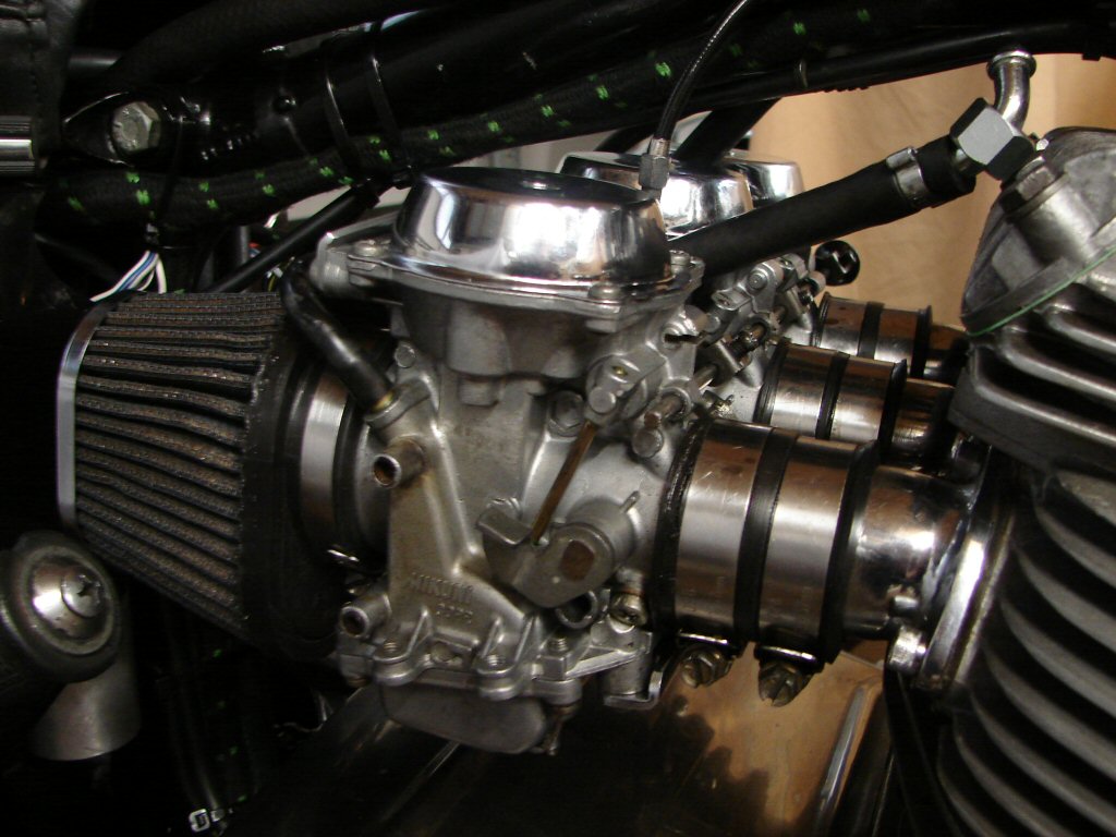
Despite oiling the new cable and greasing all parts of the twistgrip the return to idle still feels a bit reluctant, but at least it no longer opens the throttle past the stop. I now have to leave it overnight because the handgrip had to have some silicone sealant to retain it - seems the new twistgrip was slightly smaller in diameter than the naff one.
This motor has enormous torque - I reckon it would idle up the side of a tall building given half a chance - so we cannot allow the return to idle to be anything but decisive. If it has not settled down by tomorrow I will add another small return spring between the flat tab you can see on this end of the throttle spindle and the empty threaded hole below it. It is close to acceptable but not quite there yet.
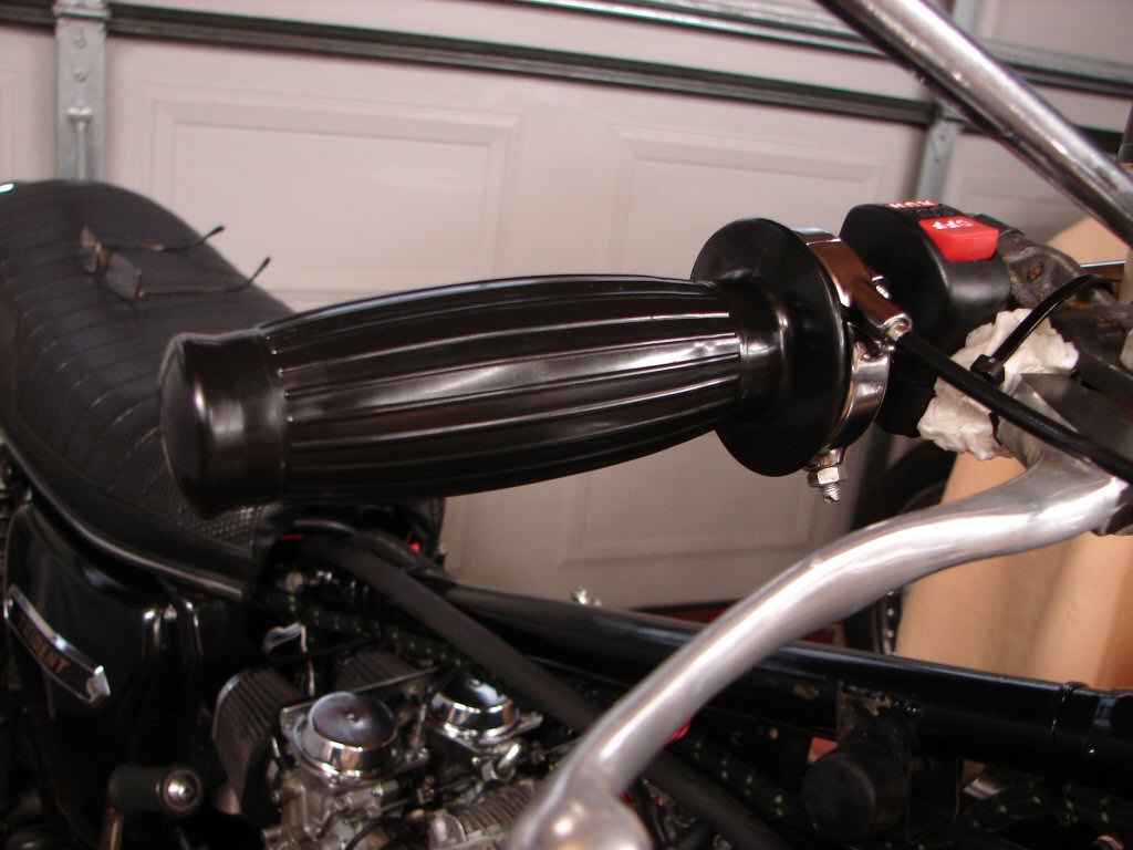
All the time I had today was spent getting all these parts back on and working properly. The new twistgrip had some issues with the handlebars and I found that there was a hole drilled through the handlebars at the very outer end, with a raised edge that was fouling things. The time all these stupid small things add to the mix makes doing this work an unattractive proposition if you were ever hoping to make a living from it - which I am not - but I only have one standard of workmanship which is what I would apply to my own bikes.
Problem is that there are very few bikes that come my way that are anywhere near as well preserved as my bikes, so it is a very uphill battle. With the increasing scarcity of the most common wearing parts it seems inevitable that I will be unable to do this work for much longer at all.
However - though this machine has challenged me something wicked I am still determined to beat it into the correct shape, as I feel that it deserves no less. The motor is nothing short of magnificent in my brief experience of it, but the riding experience is only ever as good as the worst single part of the mix, so they all have to be as good as each other.
In other news, and with all respect to you Alex - friend I have never met - I am drinking tonight, after some years of abstinence, because life on this planet is about to change dramatically for all of us and I decided to have a 'What-The-Fukk' evening.
I cannot begin to explain how unknown the future has suddenly become, hence my assertion that I intend to finish this bike to the highest standard, but beyond that, anything is possible.
There is a storm coming. A mother-of-all-storms that will challenge each and every one of us, so whatever we thought we were going to be doing next is now up for grabs. I could not even begin to explain to anyone who was not already waking up to the real nature of this world what I mean, but Donald Trump has just saved our arses whether we like it or not, and now we have to get with a brand new plan.
Our world is about to change course from dark to light in the most unbelievably good way, and the message is perfectly clear in this piece of music.
This document declaring the seven new kingdoms of our planet will give you an idea of just how much the world has changed while we were all distracted by the bullshit mainstream media fake news.
Israel will cease to exist.
Trump was right about everything.
'God' was never what we were told.
A new world of real people looking out for each other.
Still gonna freak all the sleepers out to the max but.
After numerous days of freezing shed temps I managed to pick up the thread. Gearbox oil drained, rearsets and brake lever off, outer gearbox cover off, could nearly do it in my sleep. We now have duplicates of a couple of critical parts and I have cleaned one up to compare it with what we are currently using - namely, the plunger control plate. I was not entirely sure that the taper was as smooth as it should be, and the new old plate looked to be the better of the two, but also had visible wear. I shall give both another smooth and see which one performs best when fitted.
While trialling the new plate versus the two different types of return springs I found that the larger springs that were originally in the bike did not seem to foul the underside of the new plate as the original one had, so then I decided to measure the cross section of the two spring types in order to see if I can identify which type was correct factory fitment.
The new ones are the smaller cross section, and the larger ones have a small yellow paint marker, which might either mean a factory identifier or a strength rating. They are certainly the stronger of the two sets.
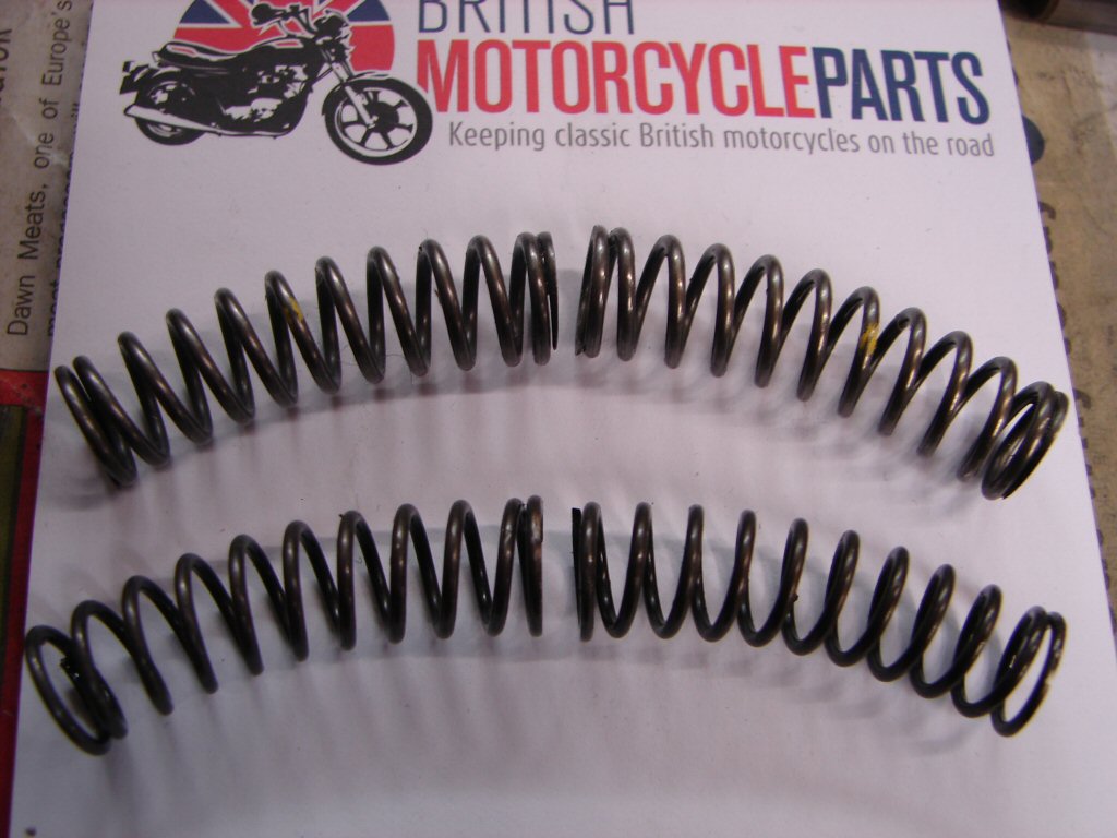
While messing with stuff going on and off the plunger quadrant I found it had significant wear in the bush that it runs in, and which I have been told others with gear selecting problems had suffered from. I was going to drive the quadrant off the shaft anyway, to see how much wear or friction there might be in that bush, but my first attempts have been in vain and it refuses to budge. It is likely that some serious heat might be needed to aid this operation, so I will prepare a jig to hold everything steady while I bash it in a wise fashion...
Meantime here are the two plates and the plungers with new and old versions sitting with their teeth matched. I get the impression that the original plungers have a steeper profile on the back, which might make them release a bit more easily, but harder to depress. It is all a bit nitpicking to a large degree, but something here simply does not work properly.
The plate on the right is the original which I had previously filed and sanded to polish the working surfaces up. So far I have only given the new old one a bit of a file, so will see how it responds to a bit more treatment. It seems to work better where the springs seat, having a deeper tab that the inner ends of the springs seat against.
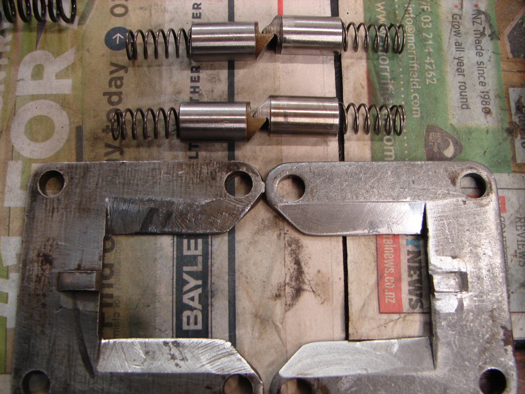
But after numerous polishings, fittings and swappings of every combination of the parts we have, it turned out that the original plunger plate had the best wearing/operating surfaces, and with the larger springs refitted gave the best centering action we could manage. Both plates have score marks from the springs, so that now appears normal.
Today I also found that the Triumph parts manual number for the return springs is wrong, so the new springs I was supplied are for a T150V. The springs for bikes with LH gearchange were uprated because of the extra friction introduced by the cross shaft - fancy that...
Despite some fairly heavy artillery I could still not budge the shaft/keyway/quadrant relationship and was figuring that I might have to farm it out to someone with a hotter flame than I have. Then I looked at the inner end of the shaft and remembered that it fits into a bush in the inner cover, so I trial fitted the outer back on and can detect no play whatsoever in the complete assembly, so I shall not disturb those reluctant parts for now.
But...
You get tunnel vision.
I mentioned that there were now duplicate parts so comparisons could be made. The small link that fits on the end of the cross shaft and engages with the quadrant shaft has a flat sided bush that has to slide slightly in the U shape of the outer end of the quadrant shaft, and one side of our bush was badly rust pitted. This would not encourage an easy 'slide'.
And then you see it.
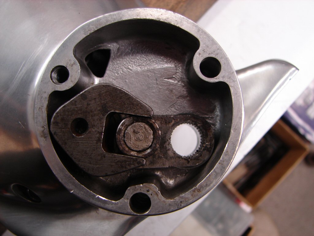
What the absolute phuque.?!
I do not recall having ever noticed the offset pin arrangement before - so I located my new item to see what it looked like.
Well stuff me.
Could it be this bloody stupid..?
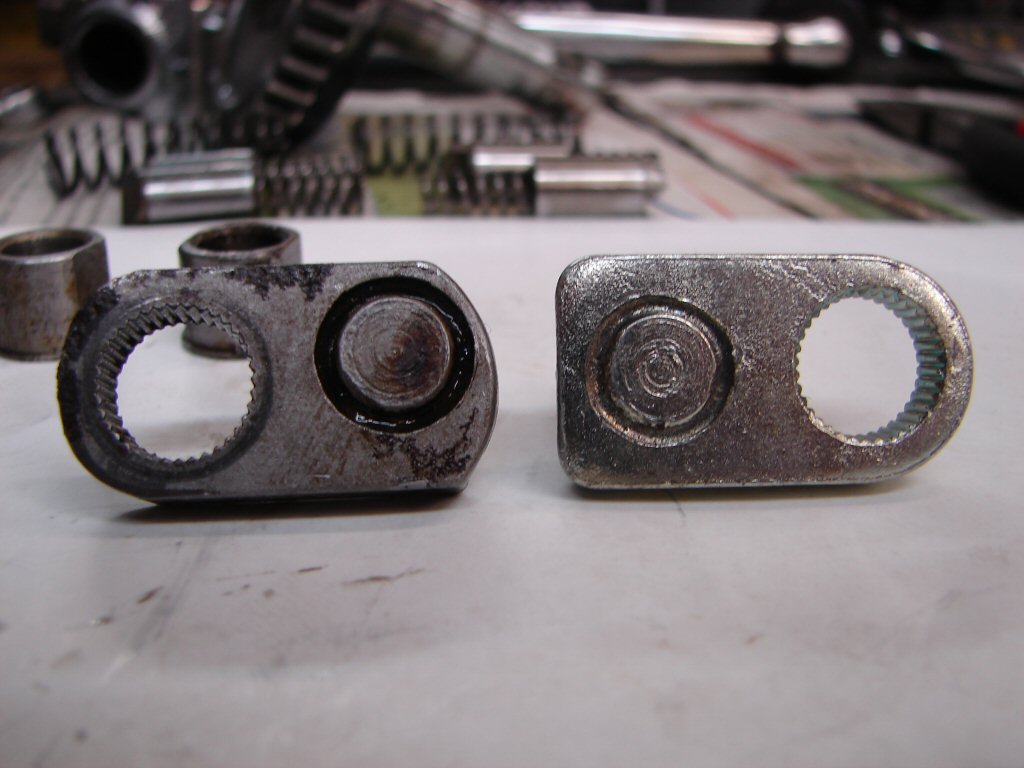
The offset link was in the bike - or someone's bike - for a long time before now, but looking at the photo of it sitting in place you can see that there would be rather limited movement available before the lower edge of the link itself collided with the retaining screw boss of the alloy housing. This would surely limit the amount of gearlever travel.
This photo tends to agree that it would.
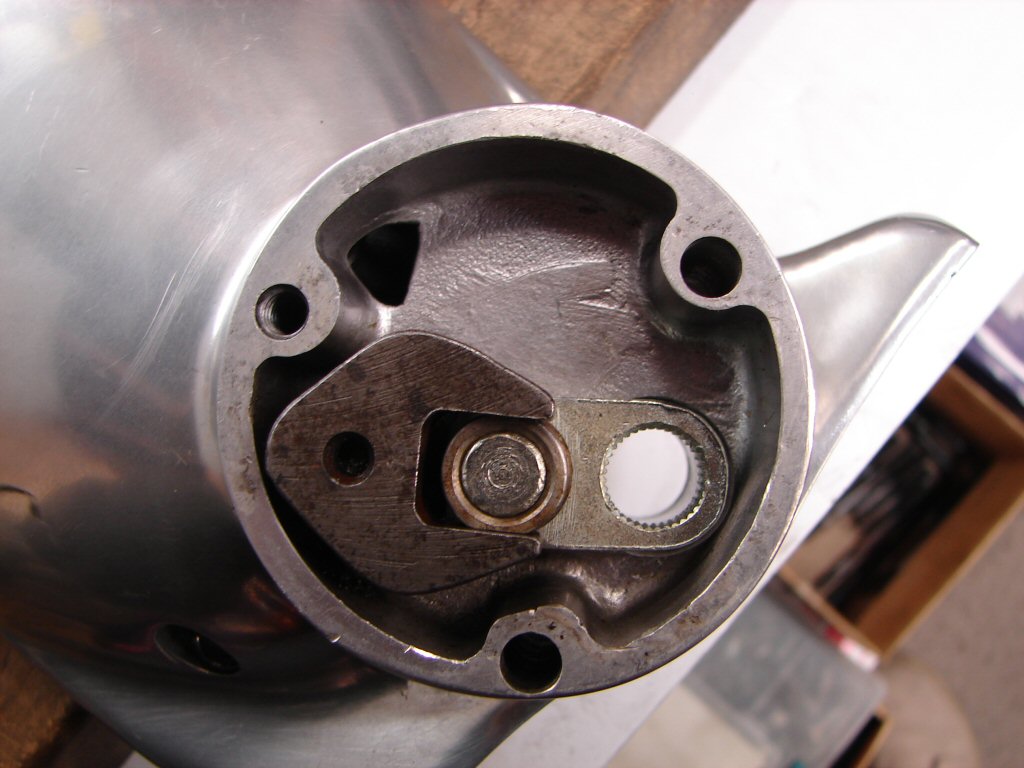
Once again, we know that not all spare parts - factory or aftermarket - are made identical, but that offset seems most abnormal and potentially problematic.
I am well past declaring that here we have the problem, but it is not as it should be in my mind, and I am now going to pluck the small inspection cover off another T160 for a third opinion right away...
Checked another T160 and the link has the pin central, so the odd one seems to have been a manufacturing error that got used anyway. 1975 quality control not the best ever...
Perhaps there are other T160's out there with offset link pins as yet undiagnosed. When altering the relationship between the gearlever - which has stops - and with the odd link fitted, it seems likely you can end up with working upchanges or downchanges but not necessarily both.
We expect to find out.
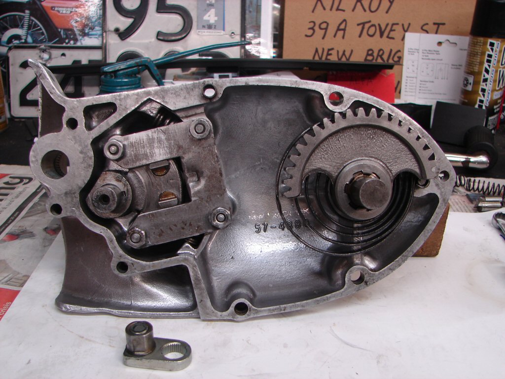
So with the original plunger plate in an even more highly polished state, the new plungers were fitted along with the proper T160 return springs, and the whole lot was bolted together. Both plungers can be seen to operate as they should as they leave the edge of the plate, and all moving parts have been treated to a coating of grease.
I considered leaving the kickstart lever off, but it is necessary in order to pretension the return spring while assembling, so I shall refit it for the time being. New link and bush lightly greased and ready to join the mix.
Taking no chances this time around, so the primary cover came off again and the cross shaft was removed to see why there was some lost movement. Sure enough the foot was moving on the flats of the shaft, so I found which way gave the best fit, then made several punch marks on both flats, after which the foot had to be wound on by the nut as it was too tight to fit by hand.
Exactly what I wanted.
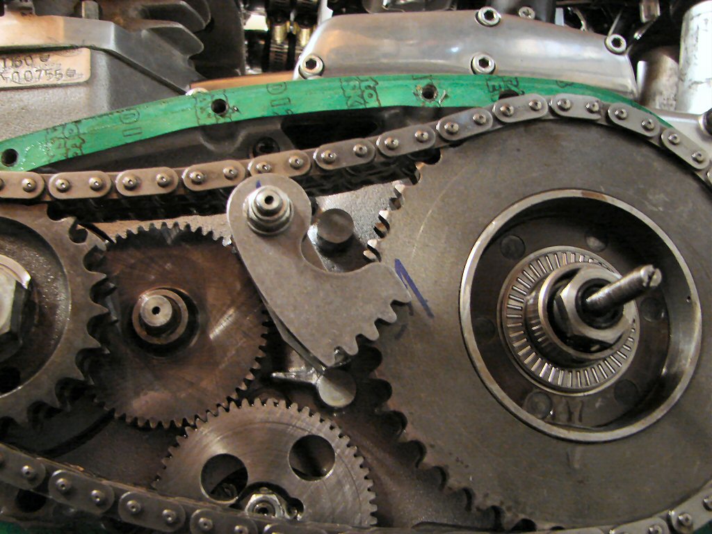
I made marker lines where the edge of the foot would be so that I could check the timing of its mate in the primary cover, and that worked as it should. I have never bothered to be this precise when assembling primary covers before, but I can't give this bike one more chance to trip me up if I can possibly avoid it.
The gearbox outer cover was introduced while the primary cover was still off, so that I could engage the new link while the foot was in exactly the same position as you see it. I shall be checking the travel of the link and its captor for the full range of movement afforded by the gearlever, during which process I should be able to select all the gears in both directions.
That would be a first...
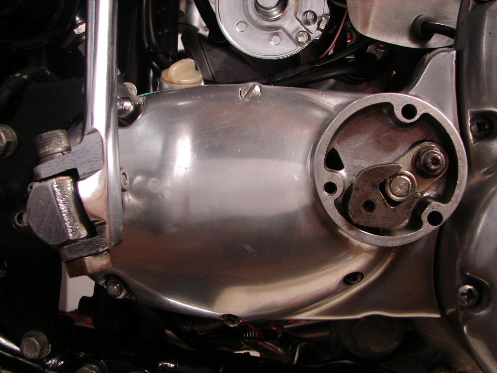
It would have been but wasn't.
The changing down problem persists - not impossible but a real fiddle. After disconnecting the rearset linkage to the gearlever it feels obvious that there is too much friction in the gearchange overall, so the ability of the selector quadrant to return to centre is being thwarted. When the outer cover is off everything feels quite normal as far as that part of the operation goes, so something about the mating of the inner and outer covers seems to be introducing the problem. The gearchange quadrant in the inner cover can be used manually to select each gear, and each position has a positive stop, so it appears that the shaft which the selector quadrant is a part of is tightening up when it is captive between the two bushes in the two covers.
So this time both covers will come off and get assembled without the rest of the gearbox.
Meanwhile I have had two vehicle breakdowns and a new laptop I was loading for a client suffered a battery failure during its initial setup. Nothing is making much logical sense at this particular time - least of all me.
Crazy times indeed.
In the process of removing the cover and looking at everything with a suspicious eye I found another problem, which has no doubt been adding to bad behaviour, although I do not give it credit for being the main issue.
I have mentioned this "thing" before, as it shares no parentage with the Hyde rearsets, but is a mongrel part of them now, and has presumably been fitted at a later date. I am sure that the proper part had dimensions which would have allowed the gearchange to have similar travel to the factory gearlever, whereas the current geometry causes more and tends to exceed the normal amount a rider's ankle can manage.
Besides this, it now turns out to be making contact with the clutch adjustment cover and may be at least another small part of the problem. There is a prominent alloy weld near the head of the pinch bolt which was the contact point, and has now been filed smooth. The lower part of the arm is also bent, so I will see if I can straighten it without enough energy to snap it. I imagine that drilling another hole at half length would reduce the gearlever travel but as we seem to have too much friction in the system I will wait until that is solved before adding any extra loading.
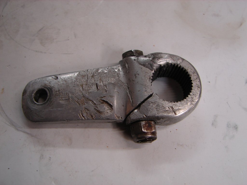
Not sure how many other faults we might end up addressing before solving the real issue...
In the search for potential sources of friction I removed the plungers from the selector quadrant then trial fitted the outer cover. Having removed all of the issues which had been guilty of causing lost movement I wanted to see how difficult it was to operate the gearlever fully between its limits of travel.
The good news was that it felt very compliant, and there was no free play anywhere that I could detect.
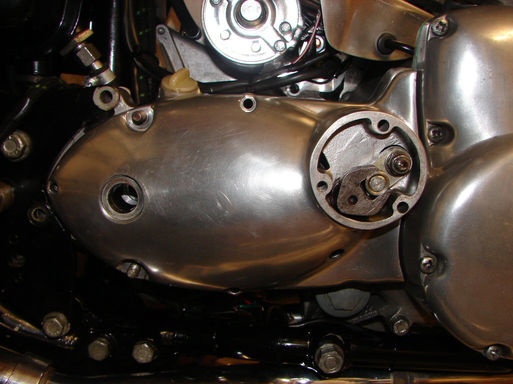
This now points the finger at the quadrant and shaft behaving badly when under load. The plungers are new but only have the same spring pressure as the originals, so it seems most likely that the amount of obvious play in the outer bush is causing some sort of lockup as the shaft gets forced sideways when the plungers push against the gearbox quadrant.
There is no way to rule this out other than to replace the bush. The bush in the inner cover is a bronze type and displays no play that I can measure, but the outer allows quite a bit of play in all directions. So I found a new bush.
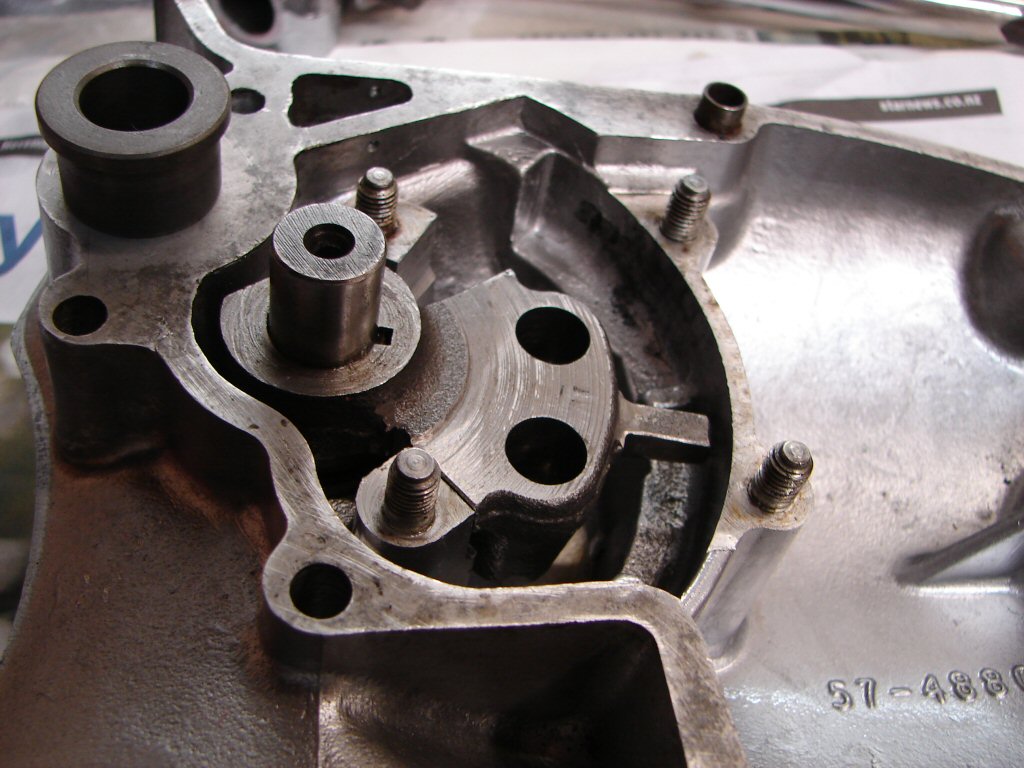
I was surprised that the new bush was not bronze but made from a harder material. That suggests that this bush was known to be intended to take the bulk of the loading that was going to be experienced in this piece of the gear selecting process.
I now have to drive the shaft through the selector quadrant to separate the two parts - an operation that I was unable to make any impact on the first time around. There is no other option now and it has to come apart. I am reluctant to farm it out as that will involve delays that I cannot predict, so I need to get clever...
Well - after several days of hard frosts and the shed a sweltering 4 degrees I managed to get enthused enough to try getting clever. With trusty butane bottle in hand I gave the quadrant a few well aimed kilojoules and then some hefty blows with a 5lb hammer and it began to move at last. I had things arranged on blocks of wood in order to avoid any damage to the alloy cover, and it seems it went that way.
The first thing I then discovered had been glaringly obvious if I had managed to think about it. This is the wrong bush. This is an inner cover bush, which means the replacements for this part have been remanufactured in the same material as the the correct bush would be, so perhaps Triumph found that these parts were wearing faster than was anticipated.
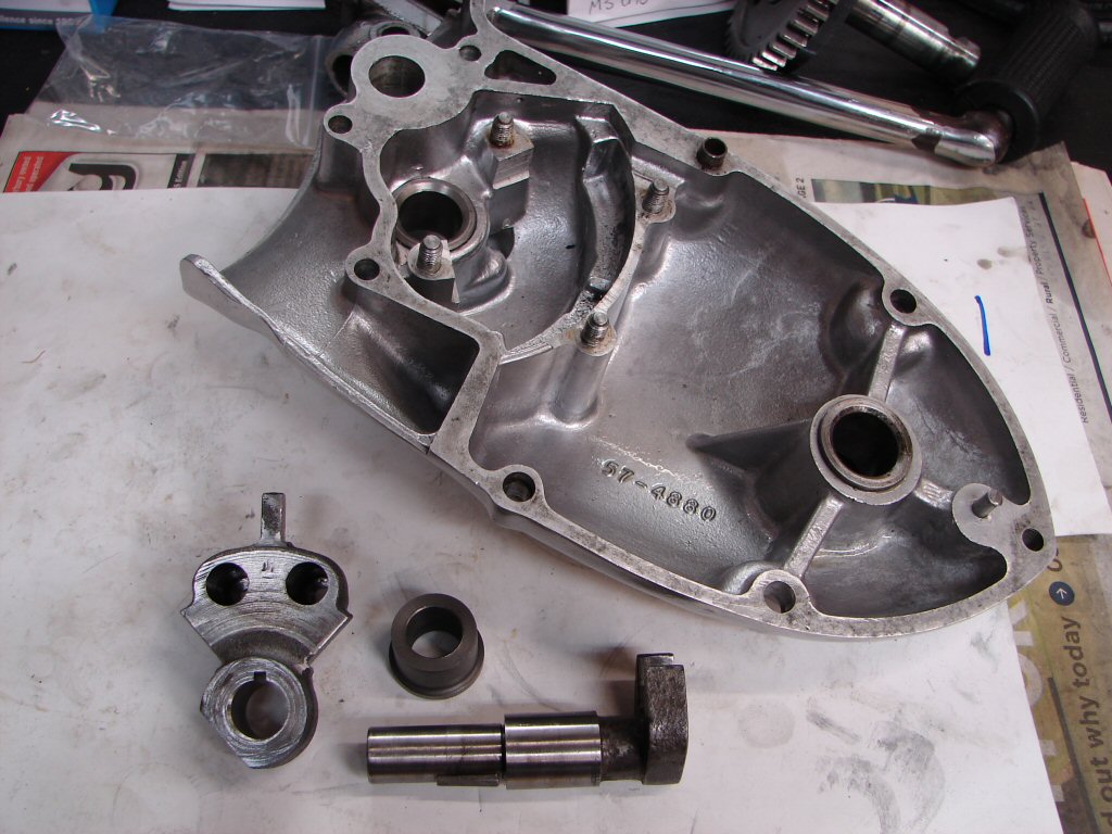
Perhaps I now also know why I have the wrong bush. There are none of the right bushes in NZ going by my usual providers. Then I found that L P Williams neither have the bush in stock, which begins to suggest that they are getting rare. I searched further and found not only a supplier in Australia with one - but more than 10 of them. Maybe they scooped the world stocks, or even had a batch made.
Oh. I now notice that these are NOS parts, so they have probably acquired stock from some business closing down.
Anyway, I was very impressed with what other stuff these guys have on hand, so have added them to my preferred list pronto, and sent them an email expressing my thanks for keeping the supply lines flowing. NZ parts people do very well with most things that are usually needed, but the limited market here does not warrant spending lots on getting parts made, or scouring the world to accumulate stocks they may never sell.
I am going to add a link to their website now for the benefit of the audience - go here.
The shaft cleaned up well and seems to have very little wear I can measure, so it will now be a wait until the new bush arrives. That should allow me time to devise another non-destructive method for now removing the original bush. I figure it will involve boiling water, but the correct drift will be the main trick...
Five years later...
With the case heated the old bush drove out easier than expected, so that was a good start to the operation. I cleaned all the parts up with emphasis on the shaft and quadrant, and as the key was firmly wedged in the shaft I left it there. The exposed parts of the case now got cleaned up too.
The new bush from the Gold Coast arrived in fairly good time, which is an improvement over past purchases from Oz. I checked and measured all the various bits and readied the new bush for its imminent fitting to the case. Once again, boiling water will be used to ease the procedure.
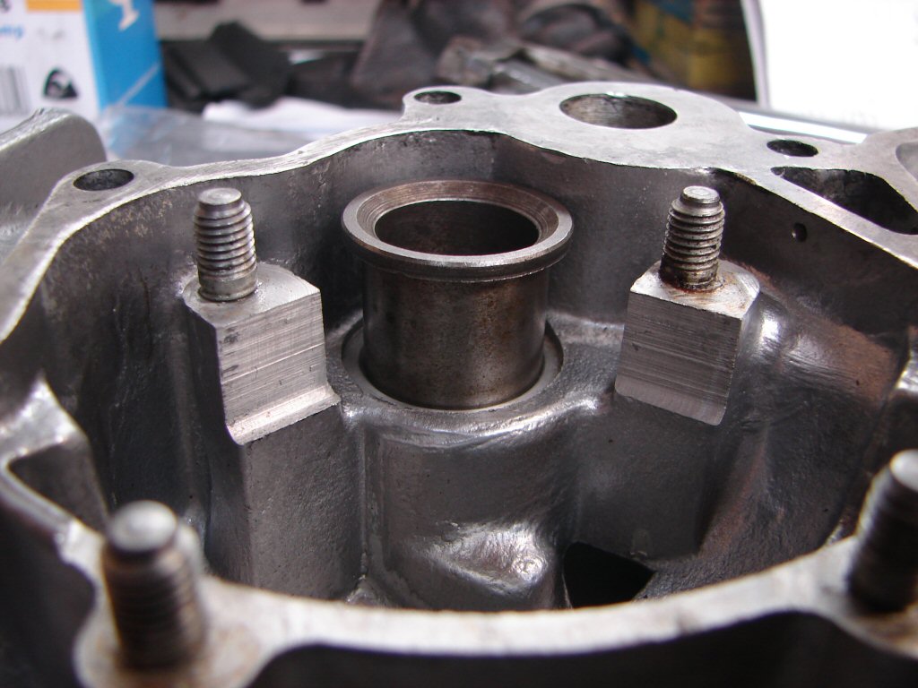
It took a lot more effort to drive the new bush in than the old one out, but it finally went all the way home, and I was pleased that the drift I had assembled was both centred and held in place so no damage was done to the narrow rim of the bush.
The bottom of the quadrant bears against that rim when in use as the pressure of the springs inside the plungers loads it that way.
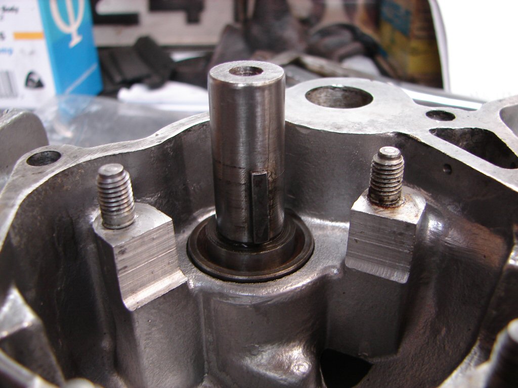
Because I was able to sit the outer end of the shaft on a block of wood on the deck I would be able to give the quadrant some pretty decisive whacks with a hollow drift, so I decided to try it without heating. It began to move so I persevered and convinced it to go all the way home.
I then found that the shaft key was right at the top of its slot in the quadrant, which it had not been before. This would suggest that whatever clearances exist either side of the bush may not have previously been quite right and now will be.
During this long and arduous challenge I have found and improved many things that were not as they should have been, but none has yet been the magic bullet. At least there are a fair few new small parts which will at least now take a longer time to wear out than you and I will...
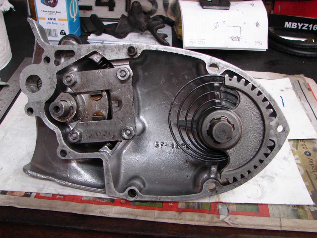
Before I fitted the kickstart shaft I had trial fitted the outer cover with and without the plungers so as to ascertain how free the gearlever assembly would move, and it feels as free as you would expect it to be. Selecting gears was possible but difficult as the rear wheel needs to be swung back and forth to allow the gears to mesh, and the gearlever is a long reach from the right side of the bike.
That plus the fact that the cover was not bolted up meant I had at least proved that I could find all the gears at rest, but that seldom relates to what happens when everything is traveling down the road.
One thing that did become apparent when trying to find neutral - so that the neutral light came on - involved a lot of up and downing as the gearlever pressure needed to overcome the drag of both the neutral light switch and the camplate plunger caused it to overselect in both directions, but not enough to engage either first or second gear.
That led me to another thought.
While I have ridden many T160's that displayed the same behaviour, it was still possible while riding to find neutral, you just developed a technique that suited the bike you were on and used considered pressure on the gearlever.
But...
While I have had the camplate plunger out numerous times in order to drain the gearbox oil - because the drain plug is hidden above the exhaust system - I have noted that the end of it is smooth and evenly rounded, so I assume it is the correct shape but have no other to compare it to. I figure I should get one or liberate one from another bike to do so.
It is certainly worth considering that the false neutrals I am finding are due to over-selecting rather than under-selecting. Either problem leads to the gearbox quadrant stopping in an abnormal position whereby the plunger teeth are not able to engage with the quadrant teeth. There is nothing above suspicion at the moment..
There has been an interruption to work due to life and the need to maintain it. I have a real job besides motorcycles...
During the down time a slight leak has appeared from the outer case gasket - I guess it has outlived the number of times it can be removed and refitted - so a new gasket will cause the cover to come off again.
I did manage a brief ride last week and found that while I could engage all gears the changes were not precise and some overselecting led to the need to change twice to get the gear required. This feels like the rearset linkages are managing to transmit too much effort, and the extra length of the actual gearlever may be exascerbating this. I have found that if I fit a standard gearlever I should still be able to reach it with my toe with my heel on the peg, so am going to try that next ride.
Searching through the spare gaskets I keep for my own use I found a pair of outer cover gaskets made of a black material and of perfect dimensions. What a treat.! Secure in the knowledge that I had a gasket I drained the oil and plucked the cover today. The heavier springs in the selector got coated with lithium grease as did everything else involved in the gearchanging process as it went back together.
It feels more like a final fit when the gasket is so obedient and fits perfectly...
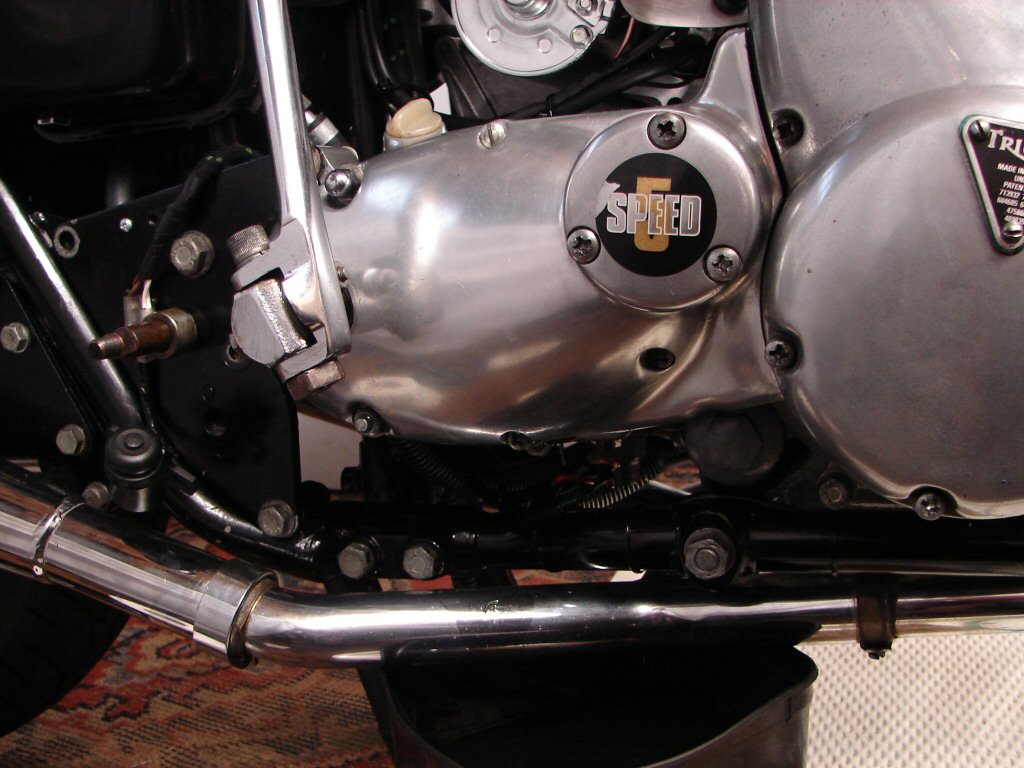
I shall swap sides now and remove the gearlever and linkages while leaving the footpeg in place. I am going to borrow the gearlever from one of my bikes to see what difference it makes. When comparing the change action on a stock setup it is obvious how much more travel there is with the rearset setup due to the length of the lever, and I had thought that moving the hole for the front of the link rod further towards the shaft would reduce the travel of the lever at the expense of it requiring more effort to do so, but I may try that if the normal gearlever works properly.
I imagine that a bit of simple geometry might even give me an idea of the ideal place to add another hole, but we will see first. The stock action feels so right, while the rearsets feel the opposite, so the design was sadly lacking in my humble...
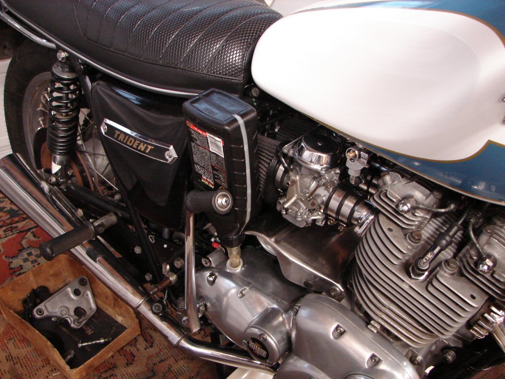
I reckon I must have nearly reached the service limit of this oil simply due to the number of times it has been in and out..
There will now be a slight pause while I ensure that there are no leaks, though I am very confident that there won't be as the new/old gasket is made of the proper stuff, to the proper dimensions, and even felt like it should - New Old Stock stuff is a real joy to rediscover.
I was wrong. There was an oil leak - but it was not from the gasket. The new neutral light switch was the culprit, and is leaking from where the switch body is crimped to the metal base. Well, I guess everything else has failed to perform properly - why would this not...
I removed the left side rearset assembly and then found a set of nuts and bolts with which to bolt the engine mount plate to the frame, as the rearsets do that with different length bolts. Then I fitted both the footpeg and gearlever from my T160.
I wish I had just tried the gearlever first. From the first test of its movement it was very obvious that there was far too much friction in the gearchange action, but the longer lever on the rearsets had not made that obvious. I dismantled the outer cover slowly to see if anything improved in the behaviour as each thing got removed, but it still felt wrong all the way.
Much as I hate having to do such things I drained the oil from my standard T160 gearbox and pulled the outer cover off it. I immediately found that it contained return springs which were the same as the new pair I bought. Even though various online experts assured me that the heavy springs with their white paint code were the right ones which had been introduced at a later stage when selection problems showed up, all three of the other T160's here exhibit a much lighter action and I am betting they have these lighter springs. Wish I had not persevered with the heavy type for so long as I repaired other bits.
Although I had found ways to reduce the friction between the heavy springs and their interaction with the quadrant assembly, they kept returning to a slightly offset rest position, which was about one half tooth displacement from where they should park. I suspect that this is why I could change in one direction but not the other. At least it has allowed me to compare two covers to compare their behaviour on the bike. It has also allowed the comparison of the effort required to select all gears by using a lever on the edges of the inner quadrant and they feel pretty much the same.
T160 gearboxes - a local specialty - or not...
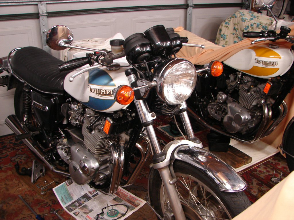
I have refitted the new springs I acquired, which have the same part number for both T150 and T160 and are exactly what the stock bike also had. The springs removed from this bike are much larger diameter coils thus were not free moving in the housing. I had originally thought that their physical size was causing some of the excessive friction to the gearlever, but got talked out of that by people whom I thought should know best.
We shall soon find out if they were right or not.
The lower case is my one which is the perfectly working sample, and our one is going back together in exactly the same configuration, or was until today's play was interrupted.
Seems to be happening a lot lately - in case you have also noticed in your life..
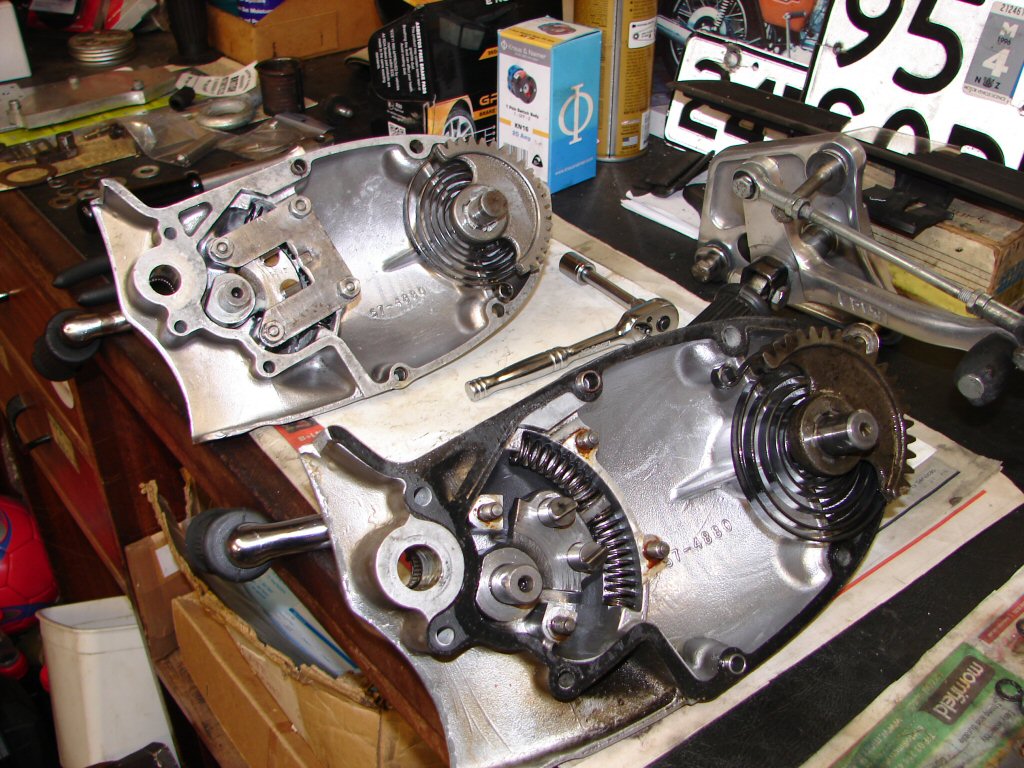
So everything got buttoned up in both covers and they feel totally similar in their action as far as effort required to gain full movement and their repeatable returning to centre after each operation.
Looking carefully there is a mark that can be seen on the selector quadrant of the furthest case - for this bike - which designates the centre position, and it is perfectly aligned with the dimple in the retaining plate as it should be. With the large springs this was always offset favouring changing up over changing down.
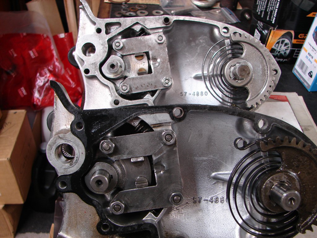
Next step will be to attempt repair of the neutral light switch to stop its oil leak. One step forward - one step back...
A friend had a thought about the varying spring ratings, and wondered if there might be an uprated spring which was not as large as the springs this gearbox came with. I can see the sense in having stronger springs considering all the extra moving parts that the rearset linkages introduce, so I found the part number for the factory uprated jobs and ordered a couple. It will be another possibility to sound out.
With an accurate vernier I found that there was an approx two thou difference in the original spring cross sections from my gearbox to the new pair I had previously bought to put in this bike, with the newer being the smaller, although I could not feel the difference when operating the quadrant directly.
Having received the uprated springs I carefully measured the sizes of all the versions I now have - factory std, replacement std, replacement uprated, and those fitted to this bike. None of the four type have the same dimensions, but are smallest to largest in the same order. Replacement std are slightly bigger than original, but as I figure we need the uprated type to overcome the extra friction of the rearsets I was more interested in those. Sure enough the fitted springs were the biggest of all, but while having a greater cross section they have the same number of coils, being 11 compared to the 10 coils of the factory fitted jobs. The fitted springs are slightly bigger diameter coils which causes some interference within the housing, so I have used the new uprated springs in the current assembly.
The neutral light switch had been leaking down the threads rather than between switch and body, so I used some thread tape and we will see if that cures it.
When I removed the rearset linkages from the left side I had found that the alloy weld I had filed had broken due to the weld being virtually only surface deep, but I thought that the pinch bolt was still holding it tight on the spline. Trying a refit showed that it was not tight enough to prevent some lost motion, so that would have been limiting the amount of travel available when changing gears the last couple of test rides. I have given the offending part to an alloy welder who reckons he can make a better job of it.
It is now all back together again except for the welding, so hopefully it will be dealt with promptly.
With the footpeg and gearlever from my T160 fitted I found that I could select all gears in both directions. I was expecting the operation of the stock gearlever to feel quite a bit heavier but it was not too much so. The return to neutral position between changes now feels more consistent, but until it behaves like this when in use I still lack confidence that this assembly method has changed enough be the final solution.
I don't know that it won't be either though...
The oil drip from the gearbox seems to be resolved, although the neutral switch may yet need further adjustment once the engine is at operating temp. As the weather had decided to play ball today I figured it was time for the acid test.
Previous cold starts have all been made using the electric start, but even with the Mikuni choke applied it has taken quite a few turning overs to catch. Today I decided to adopt my Amal method, so turned fuel on, choke on, kicked the engine over three compressions quietly then went to lock up and gear up. On my return I got aboard and hit the starter and the engine was running immediately. Within seconds it let me know that it did not need the choke any longer either, so that went off and so did I. First gear engagement felt 'normal' for the first time, and once out the gate second came up and felt the same. I had changed up to top before the end of the street and back down to first before stopping. I was then able to select second then nudge the lever down to give me neutral and the light.
Astounding.
Confidence growing I headed for the nearest 80km zone. Speedo seems to be well on the happy side, but often so is the rest of the traffic. Neutral was selectable at all the traffic light stops while standing still - which is pretty rare. Then we had some 100km road and the engine pulled clean and without hesitation. Backing off quickly gives signs of rich mixture, which may also be responsible for the instant throttle response at moderate revs, but overall the performance is impressive. Front end feels like it has fork oil which is too heavy, but brake is now predictable and not scary. No obvious negatives and every gearchange positive and precise. Hard to believe it is the same bike that has put up such a fight.
Once home I checked around for any signs of leaks, and there was some sign of a small leak at the head gasket joint on the left side. This was the first ride during which I considered that the engine had gotten hot enough to warrant retorquing the head bolts, but now it is definitely time. I would think that the valves will also need opening up a bit if things go as far down as I reckon they will.
Back in the shed and tank off for work to begin when it has cooled.
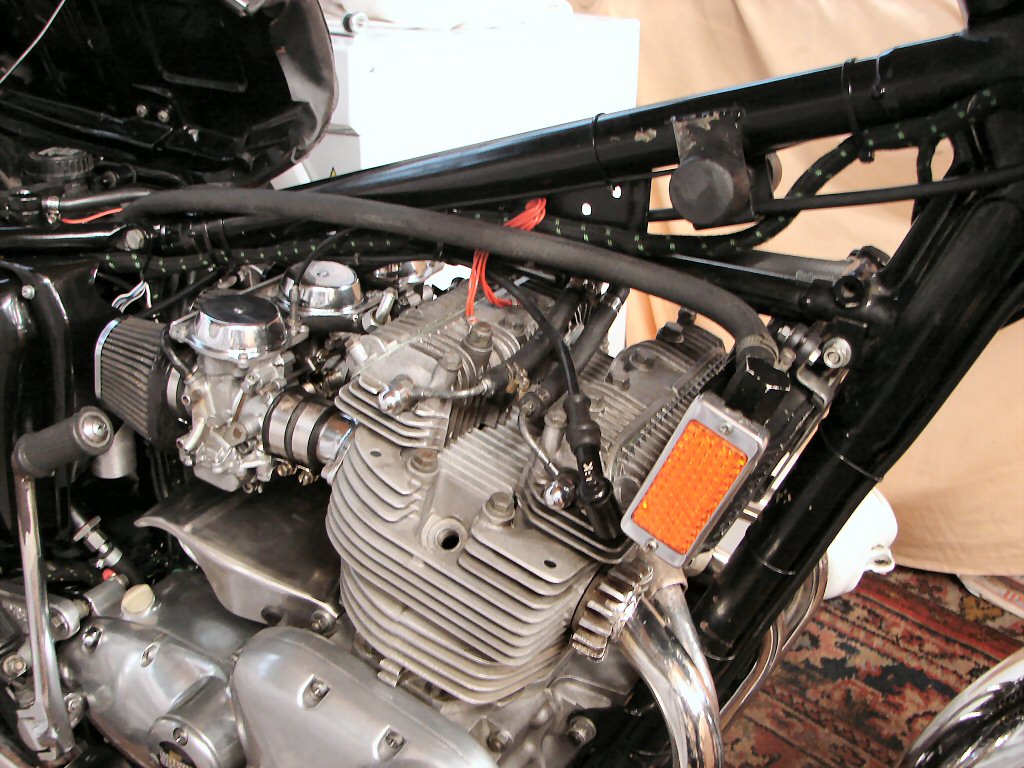
I pulled the plugs and all three are equally sooty - definitely fuel and not oil, and there has been no smoke visible at any time thus far, so rings are working their way into a good seal already. Looks like the carbs need a tune and I have no information on these carbs at all.
It seems a fair bet that these are Mikuni BS34 models, and apart from slide height settings, the only adjustment is via a small screw mounted in an upward facing recess between the slide and the cylinder head side of the carb. There is reason to believe this is a fuel adjusting screw rather than an air bleed, so the adjusting will be in the reverse sense to an Amal
I shall enquire on TOL if anyone can verify this.