November 2024
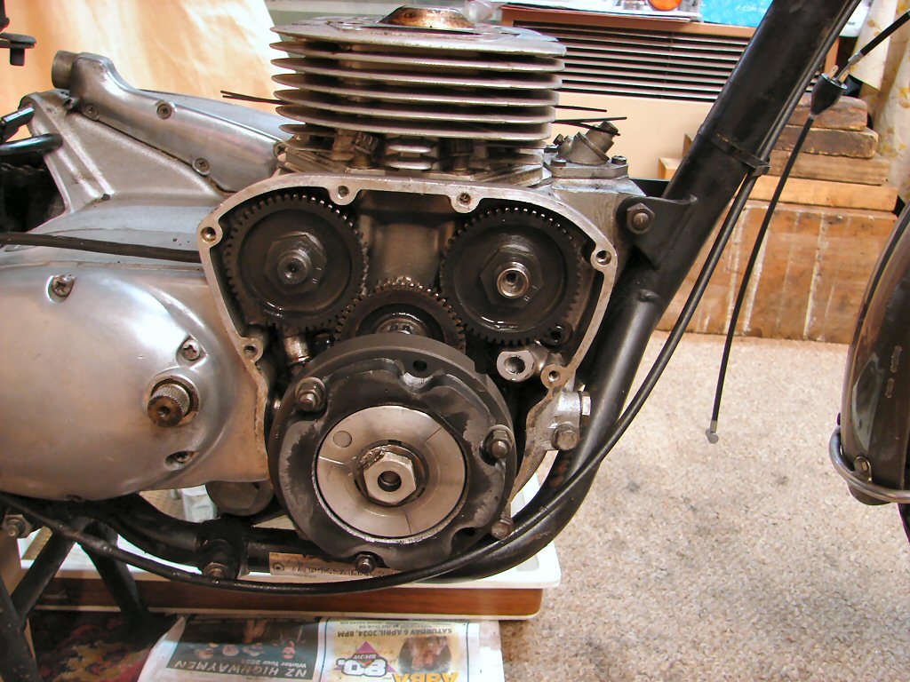
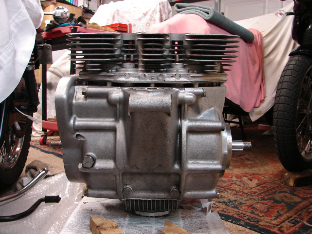
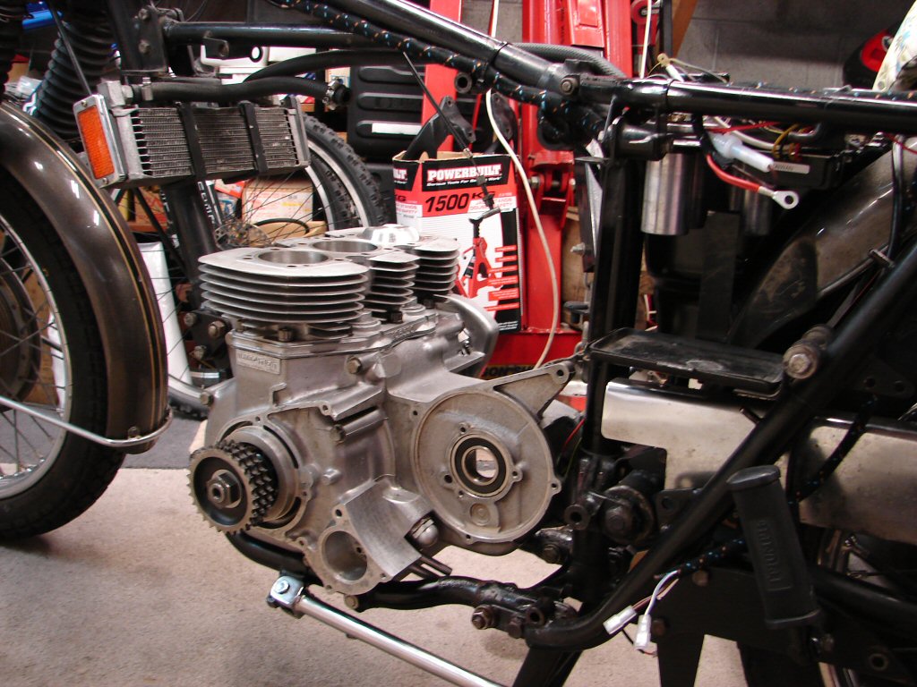
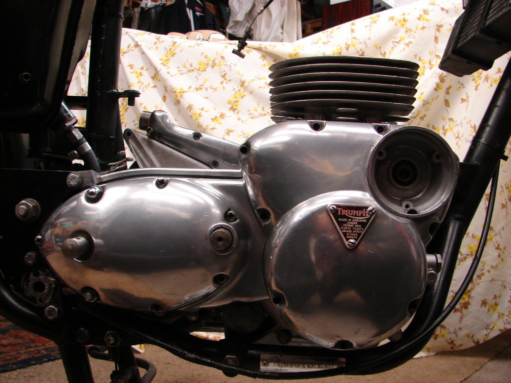
1968 Triumph Trident 750
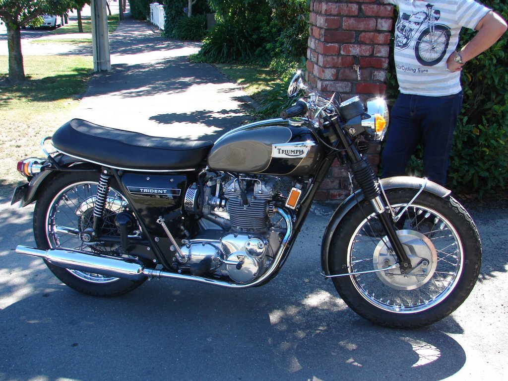
A friend acquired this bike circa 2010, and we rode some miles together on various runs in the mid South Island back then. It is a rare bike being a very early Trident with build date October 1968, although probably not sold until its model year of 1969.
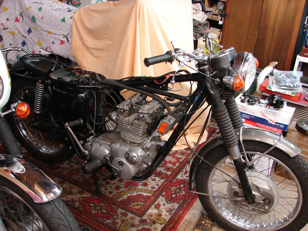
The current owner bought the bike from my friend around a decade later, and it is now in need of some attention in several departments. He delivered the bike to me from Blenheim and in very little time I had whipped quite a bit of its gear off.
Prior to undressing it I attached an oil pressure gauge and ran it briefly, discovering that it only managed 60psi oil pressure cold, which indicates quite a lot of wear in the bearings. Apparently it exhibits quite heavy crankcase breathing, so the bores may be reaching the end of their current state of oversize, which may in fact still be standard.
I then gave it a compression test and was surprised to find it managed 150/150/145, way better than I was expecting, and looking down the inlet tracts after the carbs came off showed the inlet valves looking reasonably dry, so possibly some head work has been carried out in the intervening years.
Regardless of who is doing what, the bottom end will have to be sorted before beefing up the top end, as it would be inviting disaster not to do so. As this means the entire engine has to come out we will be faced with addressing whatever else we may find, and from the sound and feel of the primary drive the cush drive rubbers will be one thing.
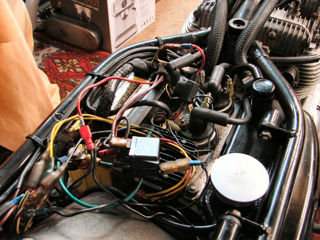
The owner supplied a new wiring loom with the bike, so the electrics will get a spruce up too. There is a Trispark ignition fitted so I am not expecting any issues with that, but I will fit an ignition relay if I find there is any significant voltage drop in the ignition circuit once everything is in final shape. Current relay is for the horns, one of which has lost its mounting bracket off the frame, so we will see if that can be welded back on.
After a long break of being involved with a prior build I am finally back on the case with the beauty kit. I am removing most of the old wiring as it is to be replaced and its removal makes all the other work easier.
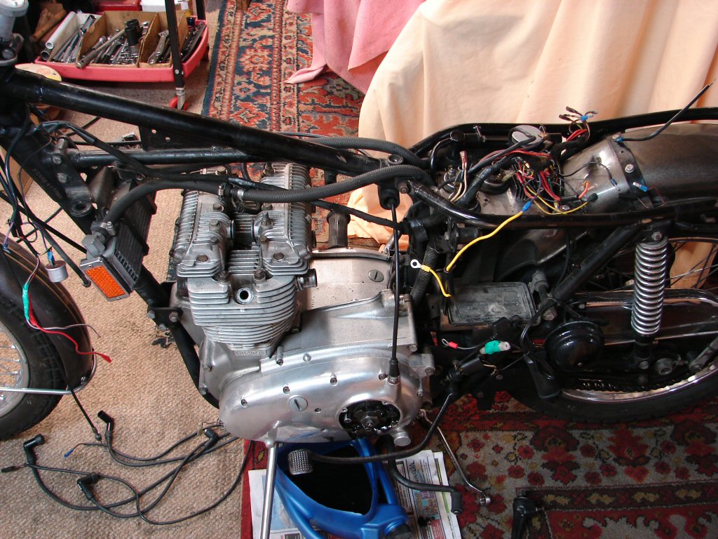
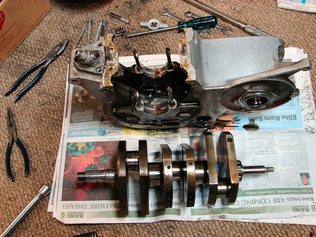
Removing the primary is one of the early tasks as it is necessary in order to strip the gearbox, being part of a total engine strip to attend to the crankshaft journals and bearings. After ascertaining what undersize of bearings will be needed depending on the condition of the crank I bolt the new bearings into rods and centre crankcase and have the crank ground to suit those dimensions.
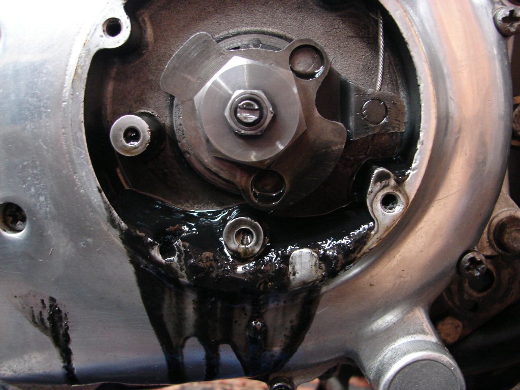
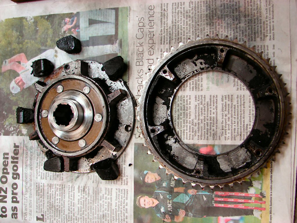
The very first reveal is this hideous looking sludge, which indicates that the cush drive rubbers have turned to mush.
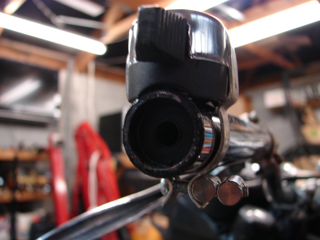
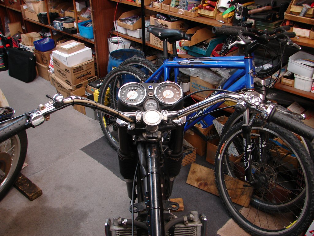
There are new handlebars to be fitted as well, and they will need to be drilled to accept some of the old switch units, plus the mounting bushes need some attention. I decided therefore to remove the 'bars early in the piece so that I can move around the bike without getting a bar end in the eye from time to time.
When removing the aftermarket indicator switch I was reminded that I think differently to some other bike mechanics...
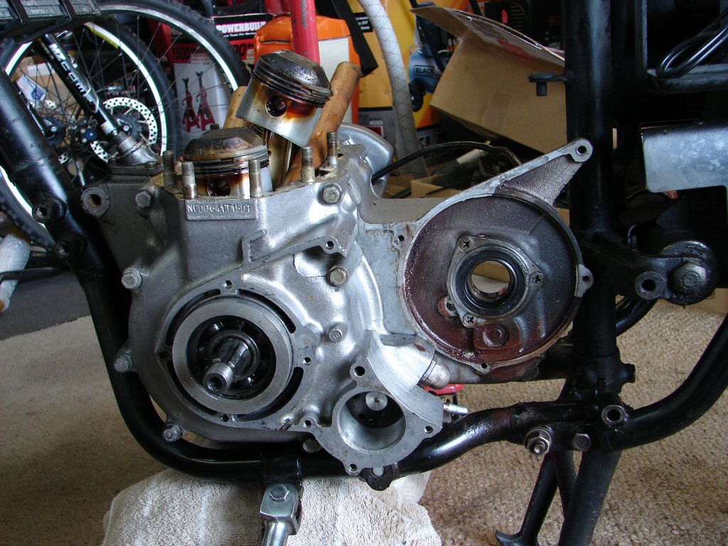
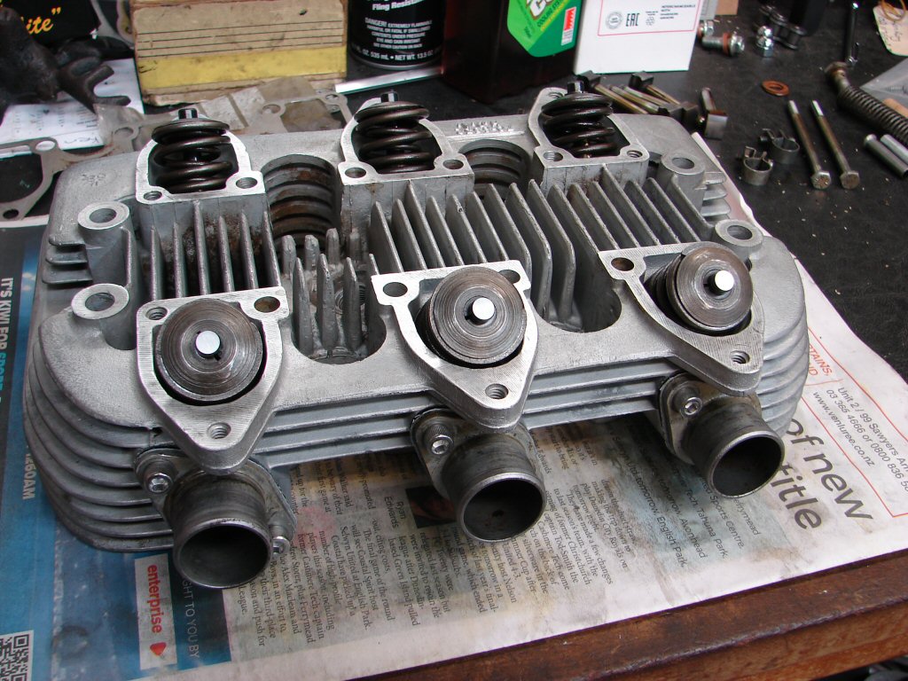
Removing the cylinder head is the first step in actually pulling the engine itself apart, and there were a few disconcerting discoveries. Besides a few stripped threads I discovered some previous repairs on the rocker box where a stripped UNC thread has been repaired with a UNF helicoil, which is seemingly already heading in the same direction as the original. Not sure if there will be enough meat left to put it right.
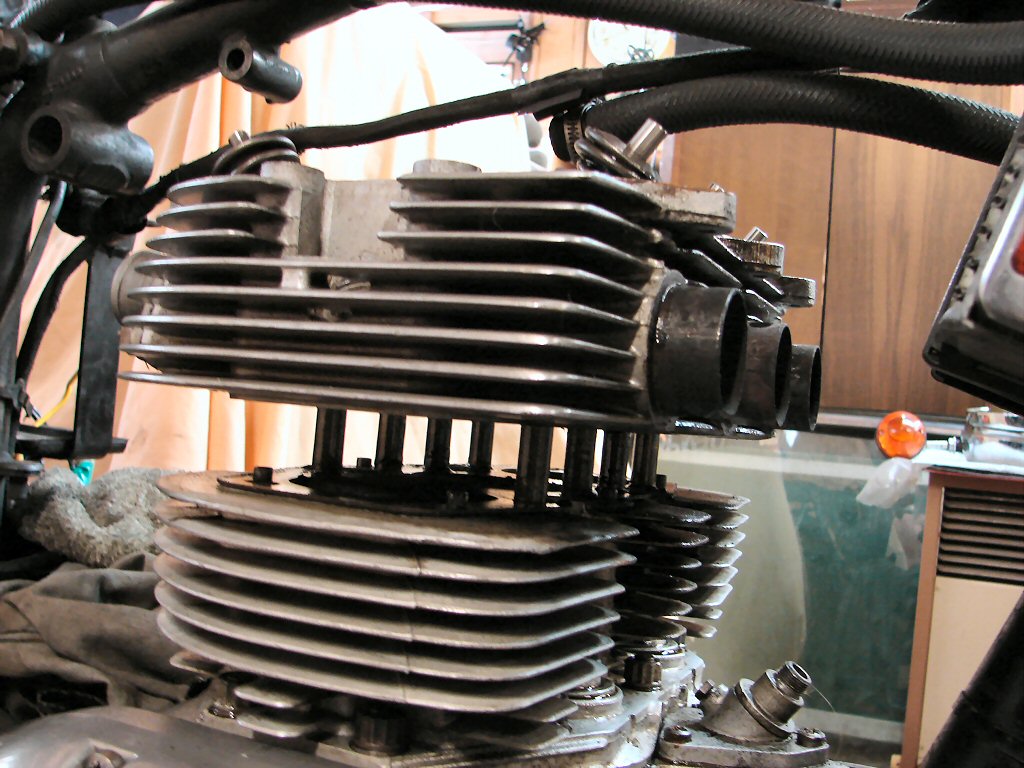
The cylinder head is putting up one hell of a fight, and for the first time ever I had to use a car scissor type jack on top of the breather housing to lift a wooden dowel inserted in the inlet port to even break the seal of the copper head gasket, after which judicious tapping with a massive drift beneath the exhaust ports has only gotten me to having the head still firmly stuck about half an inch up the pillar studs.
I see we also have another kickstart cotter pin fitted the wrong way around. Easy fix for a worthwhile improvement at least.
At close of play I had the headlight off while disconnecting obsolete wiring, and had found a few issues with the wiring which makes me pleased we have a new loom going back in eventually. The indicators are a later addition to the bike, so will not be acommodated for in the new loom unless it is also intended for later models, so I will likely be making a separate loom for those.
The main reason for the strip being total is because of low oil pressure, and I had commented to the owner that if the oil light had been working he may have gotten a flickering oil light at hot idle. A bit of a worry then to find that the oil light had been disconnected at the switch.
Hmmm. Makes you wonder. Perhaps we will find that the switch is faulty.
The head continued to fight all the way. With "first, do no harm" playing in my head I continued to tap my way round and round the base area of the inlet and exhaust ports, where there is adequate metal to avoid any incidental harm it inched its way up the pillar studs.
Even at this stage it was still stuck as a stuck thing..
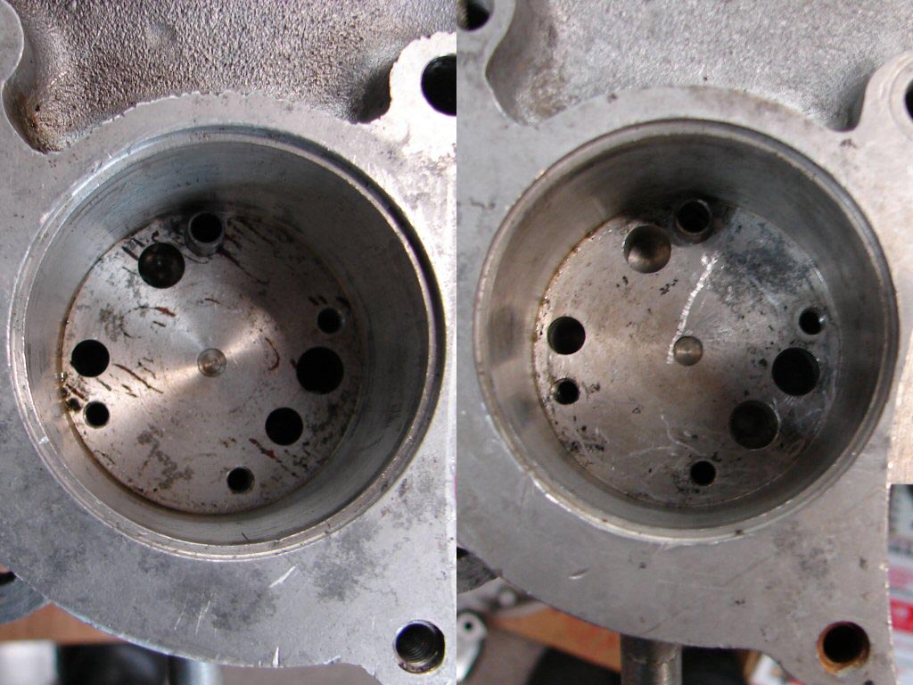
As the pillar studs cleared the head it finally agreed to play ball, and revealed one very black pillar stud and copious amounts of oil everywhere. The main offender was one of the two centre exhaust studs, and it appeared to have sauteed oil coating which had presumably baked to the head. I will check at a later stage if for some reason this head is particularly tight on all the studs, as it seemed that was the case.
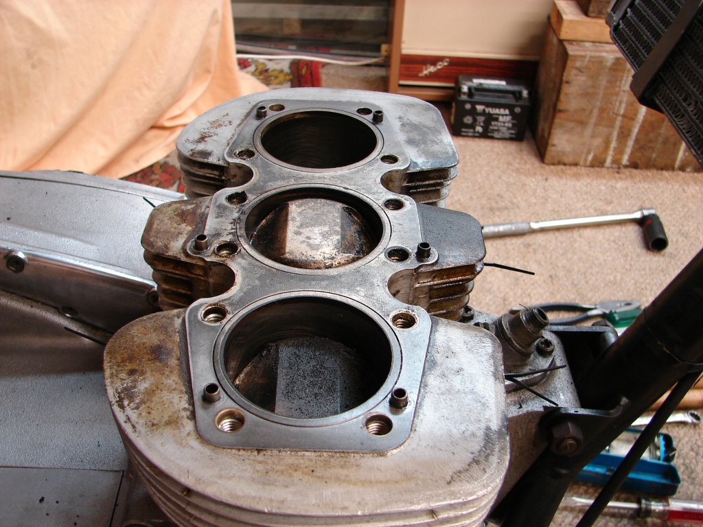
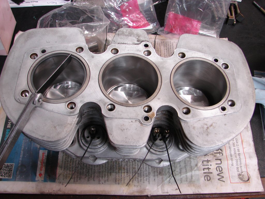
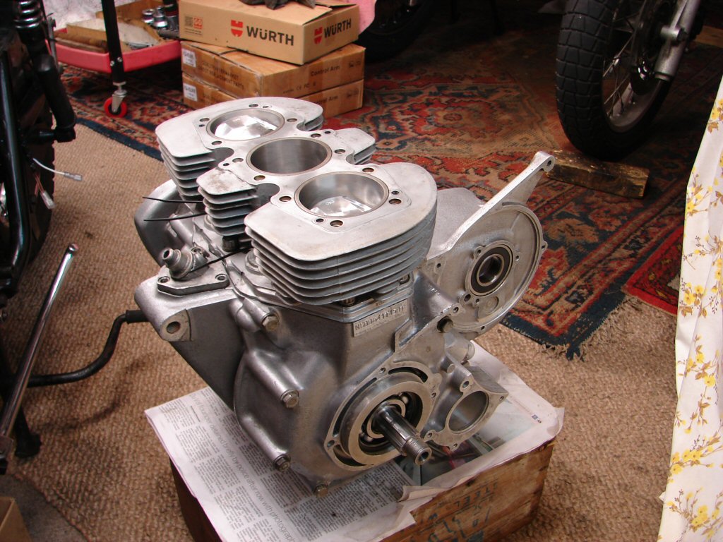
The pillar studs all came out with no trouble at all, and if anything were a bit on the loose side, but all the threads look to be intact, which is a win. I cleaned the oil up and gave the centre piston a rudimentary clean to reveal 'STD' on the crown, so the motor has never yet been rebored from standard. I can rock the pistons considerably in the bores, so it is definitely needing a rebore now. I imagine we will get away with +.020" which are the smallest oversize pistons available these days.
Evidence of a persistent oil leak around the area where the troublesome pillar stud lives.
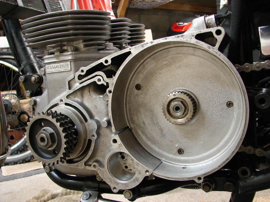
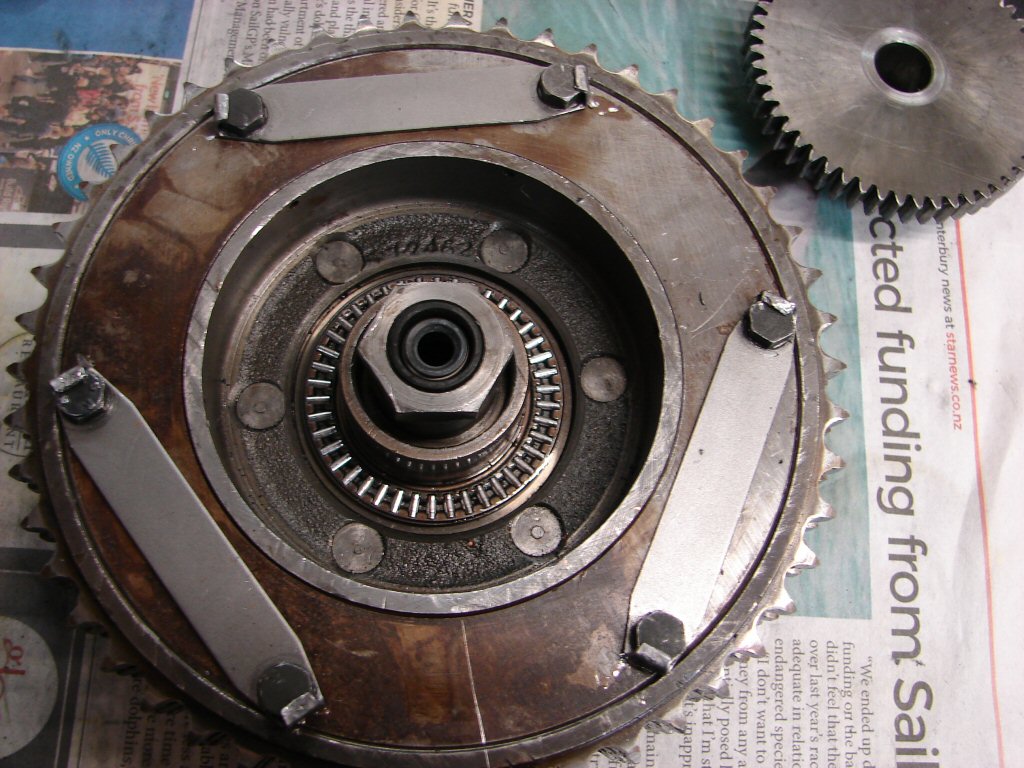
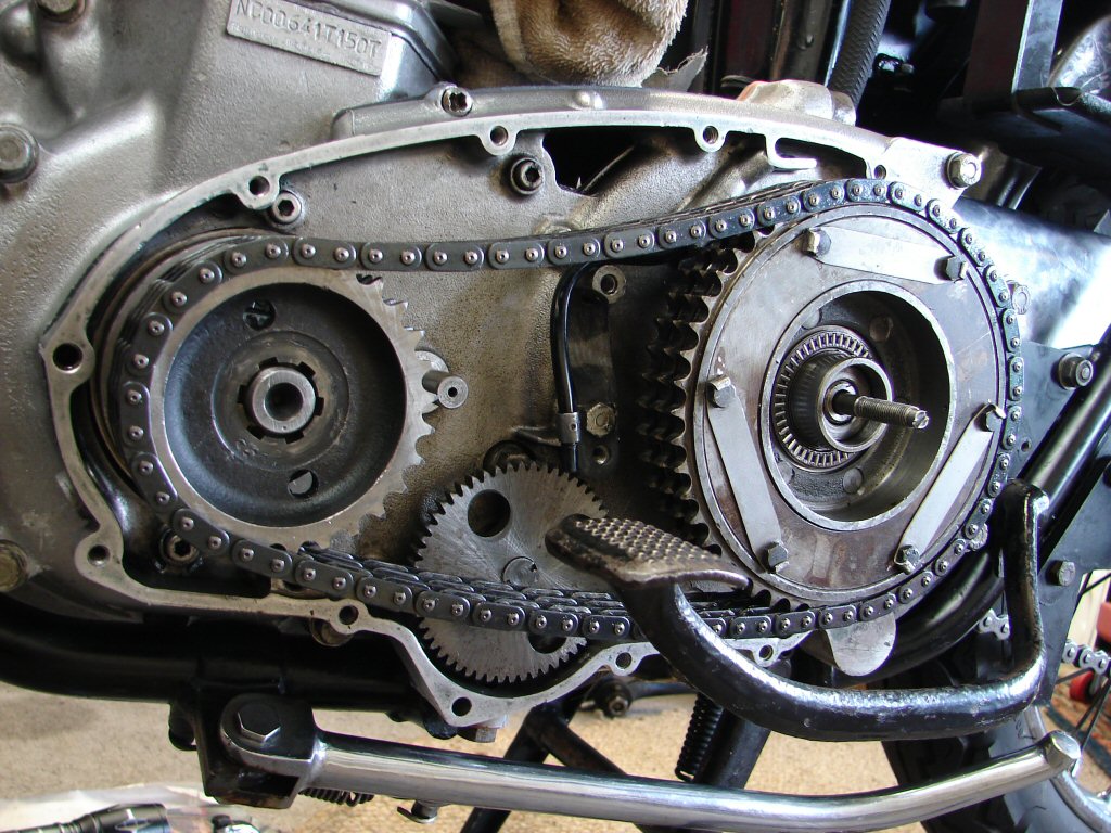
I turned my attention to the primary drive, as it is easiest to undo all the heavy duty nuts on both ends of the crank while the pistons are still supported. I had to use an impact driver on every one of the original phillips head screws, but the colour of the gasket indicates that this has been apart in the not too distant past.
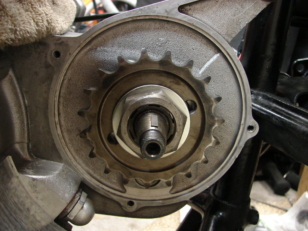
I resurrected the rear brake expecting a fight from both the cush drive and front sprocket nuts, but they turned out to be only finger tight, or perhaps finger loose. The sprocket nut had been prevented from falling off completely by its locking washer which saved much destruction.
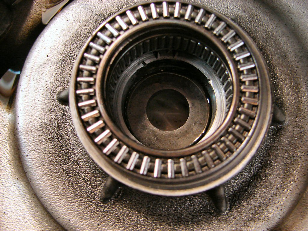
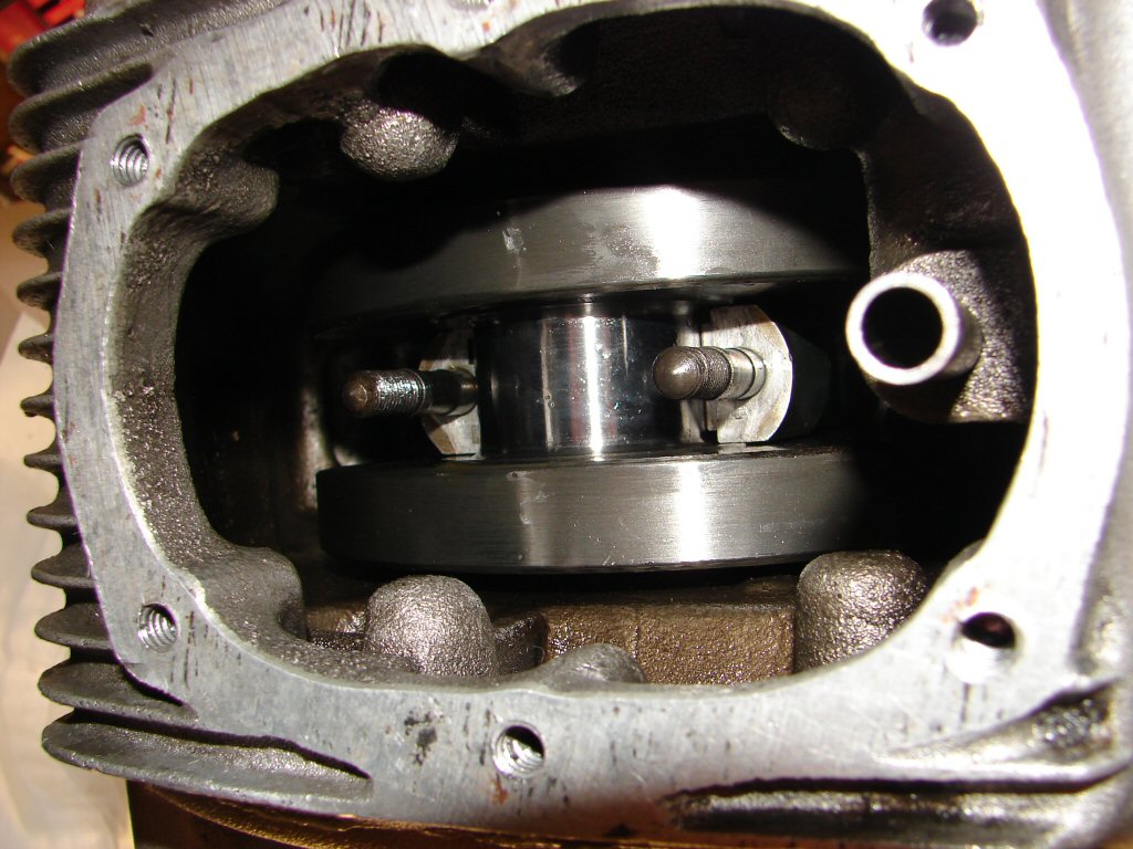
Meanwhile the cush drive nut had loosened as far as it could go, which is right inside the outer needle roller bearing and sees it colliding with the alloy housing behind the clutch ramp. Some damage to the flats is visible in the above pic.
The housing does not appear to be too concerned which is nice, although I shall examine the needle roller carefully to make sure its diet of alloy grit has not aged it unduly. Nice to know we are going to be effecting quite a number of improvements however. The cush drive rubbers alone will make a world of difference to the smoothness of the drivetrain, and we shall see how the clutch has been coping when it gets outed.
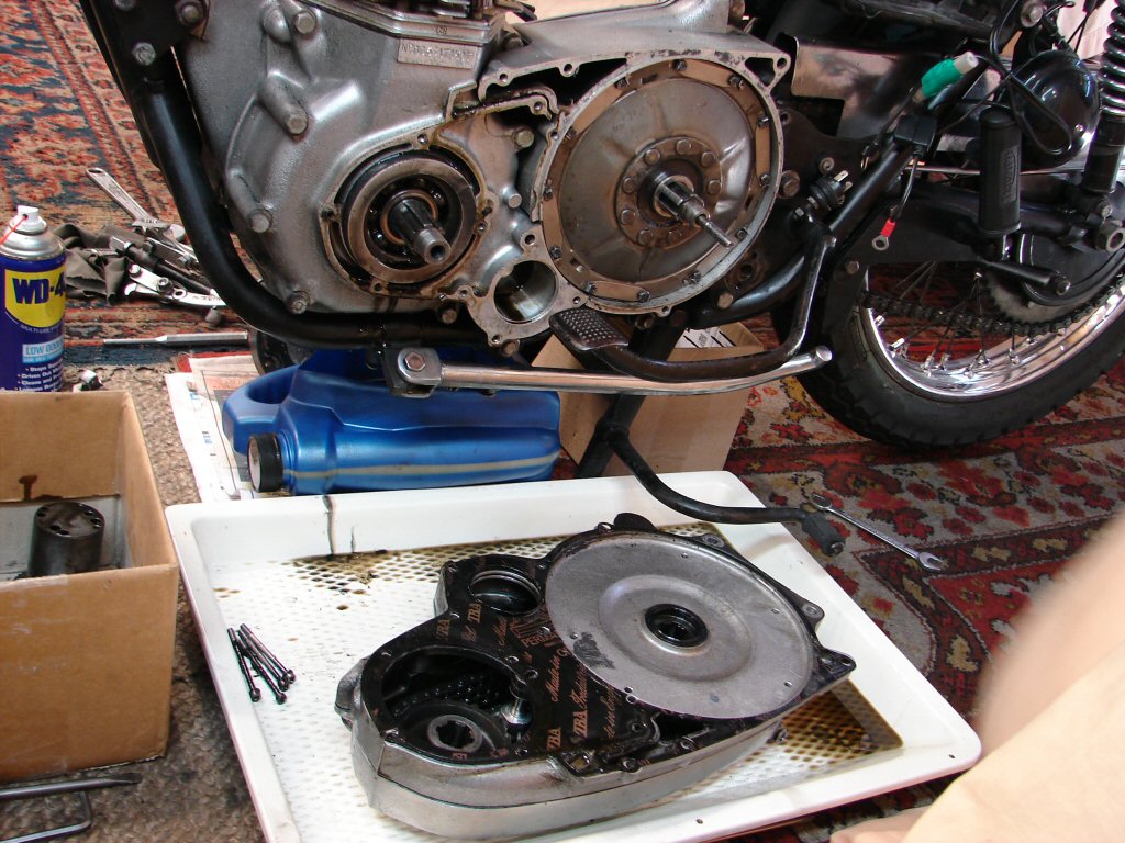
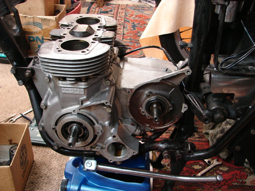
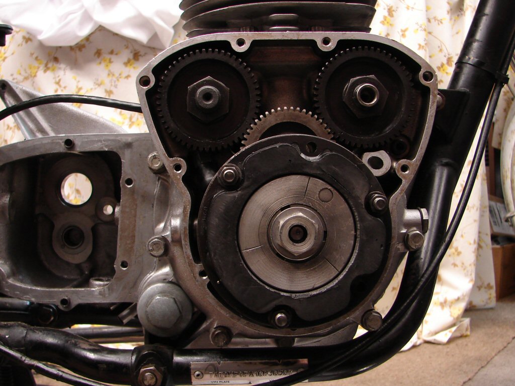
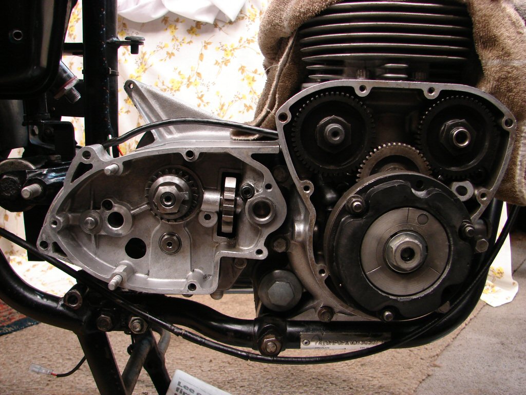
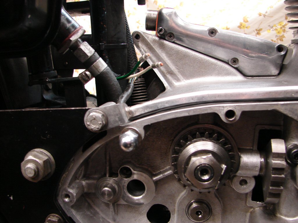
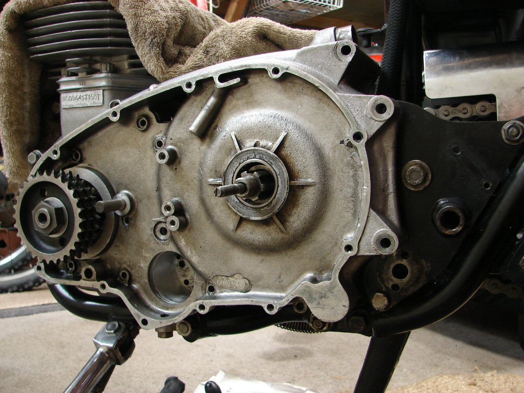
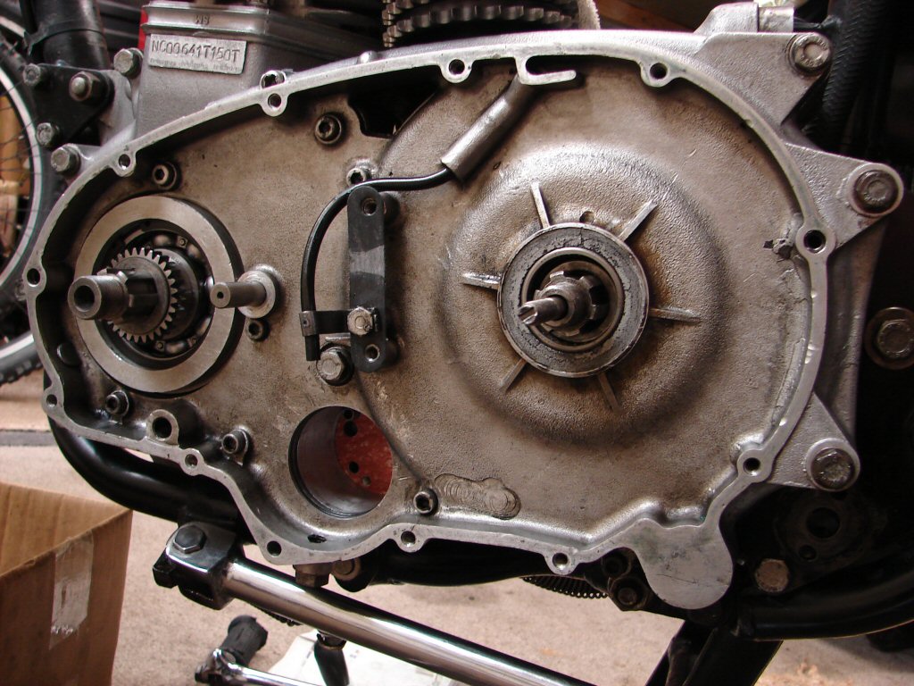
Timing cover comes next, as the alternator rotor nut usually takes some persuading, so the primary chain and rear brake must remain functioning to facilitate that process. The Trispark pickup plate comes out first, along with the rotor, which they happily did.
There is always a bit of oil that pools in the bottom of the timing cover, so the oil draining device was positioned appropriately and all went well. The oil was equally black to the primary drive side, as of course it has been circulated around the entire engine. Apart from that everything appeared to be where it should in the timing case.
That is - until the oil repository was emptied into my waste oil. I drain old oils off slowly lest there be anything significant therein which might give clues as to things untoward. And indeed there was.
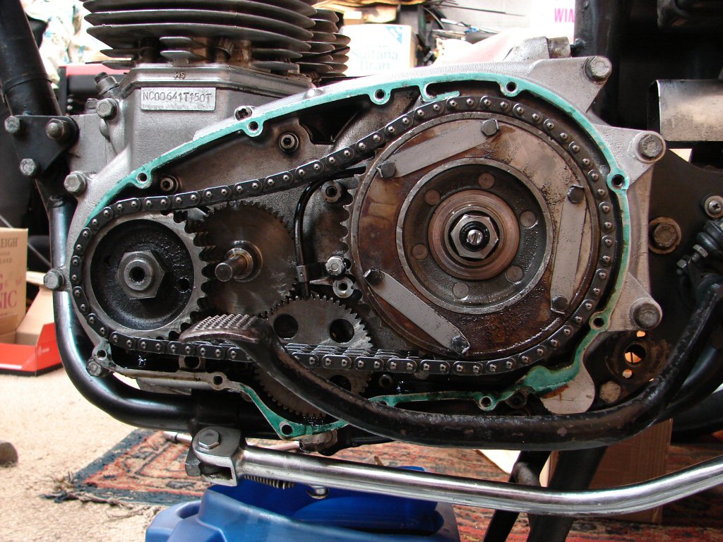
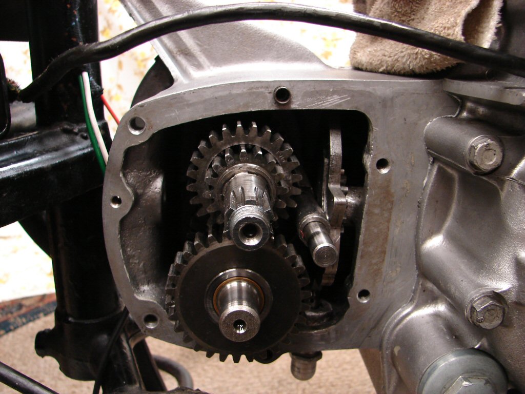
It is quite a shock when one finds things that spell some sort of disaster, however large or small it might be. Although I had drained oil from the lines plus the crankcase before the timing cover, as soon as I spied the two broken teeth I figured that they were from a timing gear. Sure enough, and at least one was visible in the previous pic if you were looking for that sort of thing...
Although it will not be exposed until the alternator is removed, it seems that neither teeth are from the camshaft gears which is a blessing. It does not rule out the crankshaft pinion but all will be revealed in due course.
Not sure how difficult it might be to obtain such a gear, as I have never had the need, although I will also explore collections of previous wreckage to see if any such thing may already exist here.
For a growing number of reasons it is becoming increasingly obvious that we have intervened in the life of this engine not a moment too soon.!
Fortunately the errant teeth were both from the intermediate gear, but with no evidence as to why they decided to leave town. Checking the mesh of good teeth with the pinion did not reveal any major wear, and using a magnifying visor I could not detect any gouges that might result in a stress failure. We shall consider the pinion fit for another tour of duty.
A replacement gear has been purchased and is on its way, so the only major consideration will be to accurately check that the cam timing is spot on despite whatever timing marks may be on the new gear.
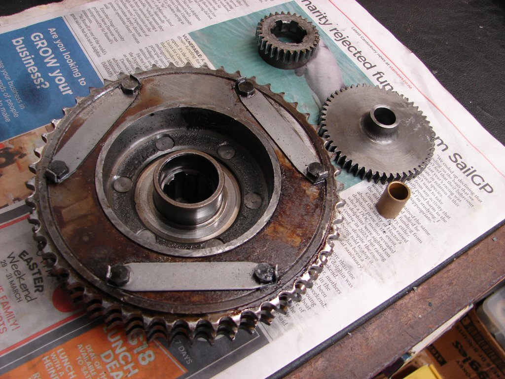
The primary drive was next to be removed, and both sprockets pulled away easily having been running slightly loose. As is often the case the oil seal in the cush drive retaining nut was reversed, so there may be a bit of oil inside the clutch when we get there.
The oil pump came out without a fight, as did the inner primary case, as none of the screws were particularly tight. I get the feeling that someone has been inside the primary not too long ago. The clutch assembly also looks kinda clean, so maybe that has been tended to.
Sure enough, we appear to have a new clutchplate installed not too long ago, so the reversed oil seal has not had a lot of time in which to leak. There is a self-aligning pullrod fitted and the bearing feels very good, so I think we have a major win in the clutch dept.
The clutch hub put up quite a fight, which is a good sign, and trial fitting it in the clutchplate proved a good firm fit. Excellent. These two parts alone would add $450 to the cost of this rebuild using what is currently available.
The clutch housing required the impact driver treatment to release, after which the engine plates joined the growing pile of bits in boxes. Rear brake lever arm was quite loose - its a trend...
The front sprocket nut was finger tight and only retained by the locking tab washer. Removing the chain to get the sprocket out revealed that the chain is totally shagged, with numerous tight spots as well as being at max adjustment. We sure are going to make this bike a happier unit. The sprockets look to only have travelled the mileage indicated on the speedo, so they may be original fitment if that is genuine.
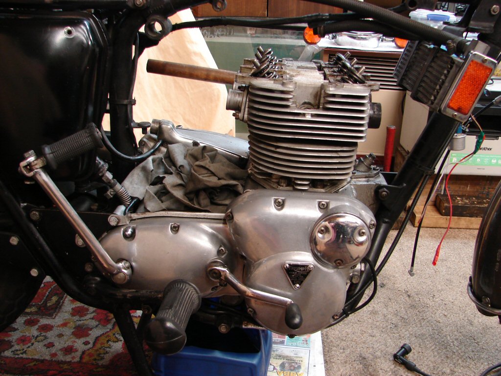
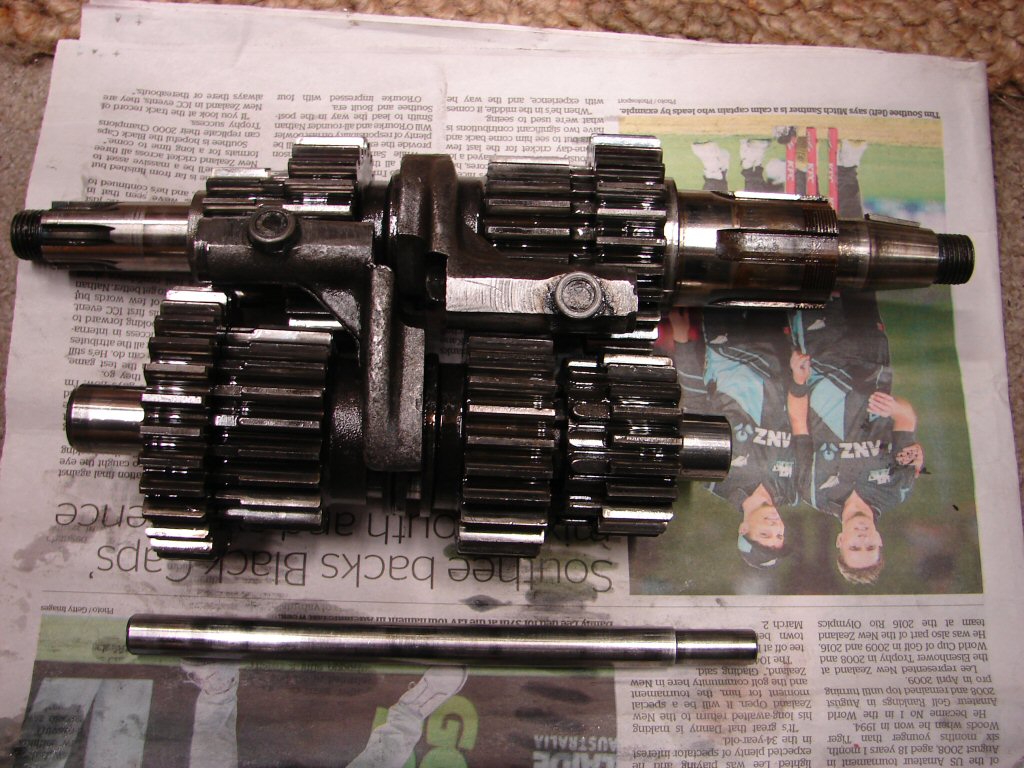
Next step gearbox strip, after which the barrels can come off and the motor leave the frame. Pleasing to have made such a huge visual difference today.
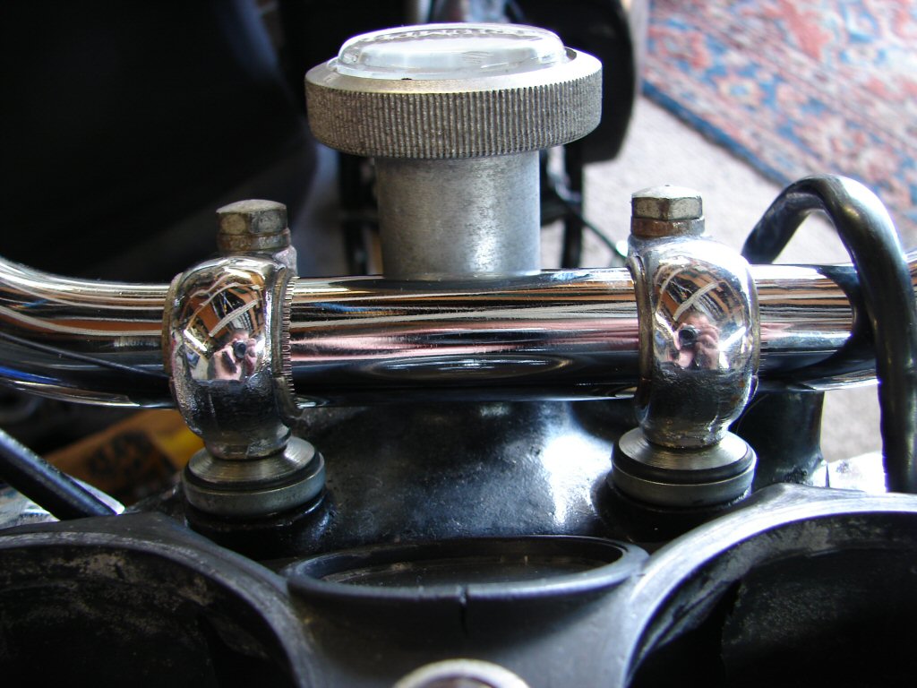
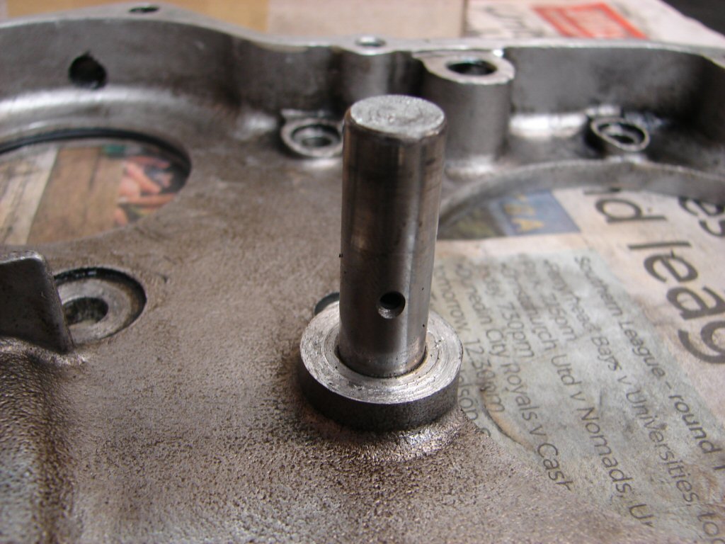
It just occurred to me - the sidestand is rather awkward to extend as it catches at half travel, and looking at this photo explains why - that minimal bolt head is intended to be underneath, and is made that way so that the stand return spring can clear it when operating either way. I guess they wanted the polished bit in view, but it shall be leaving...
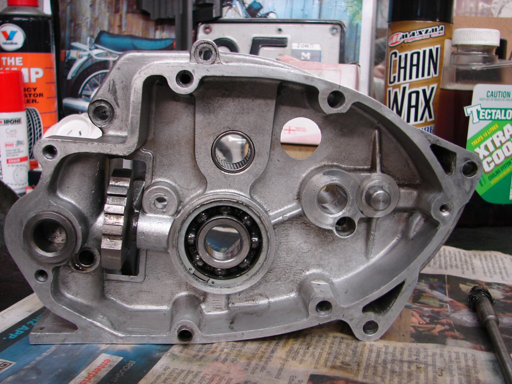
The gearbox cover came off happily, but then I spied the kickstart ratchet nut and remembered that they are torqued up pretty tight, and I now had nothing on the drive side I could lock the mainshaft with. I decided to loosen the locking tab anyway, whereupon I found the nut to be only finger tight. Whoopee.
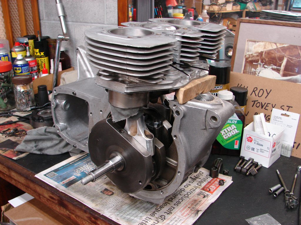
The engine now only requires front and lower mounting bolts removed and it is able to be lifted out, although having the trolley jack beneath it makes swivelling it around to clear the frame a breeze.
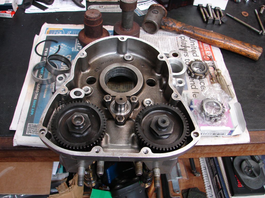
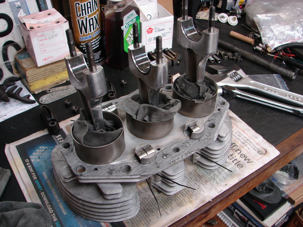
Pistons were first off so the rods could be protected, then the timing side case removed with camshafts in place. This will allow static timing the new gear before the engine goes back together.
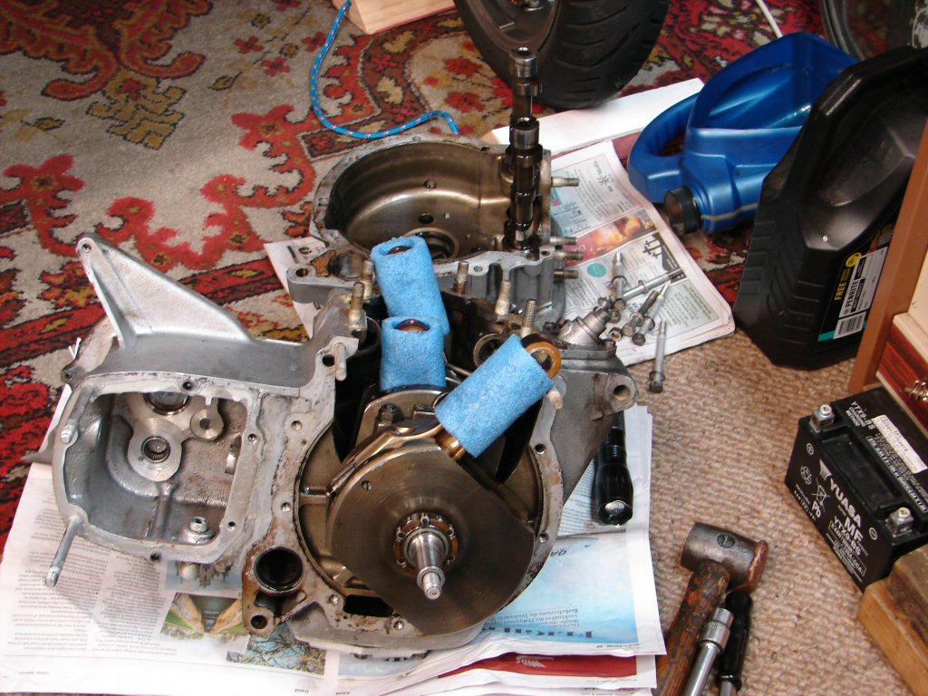
I have seen the horrendous damage an errant conrod makes on its way out when the rod has either broken or the cap has come off, and always wondered how long it takes for say, a loose nut to result in a fractured cap and the "irresistable force meets immovable object" scenario plays out.
Well, as a personal first, the first conrod to be liberated was the timing side No.1, and both nuts were loose. The self-locking mechanism had thus far kept the nuts at the top of their thread. but no doubt they would have capitulated over time. The centre rod was torqued correctly, but No.3 was the same as the first, and the nuts wound off with little resistance. It seems my former comment of intervening just in time bears more fruit.
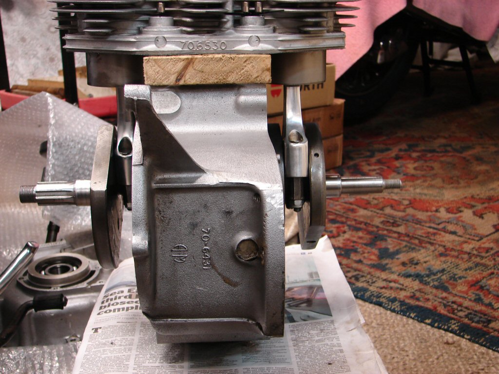
All the bearings are copper/lead and standard size, so these were fitted by the factory in 1968 by my reckoning. When I released the bearing caps, the shells just fell out of the rods and caps, when usually they are quite a firm fit. I figure that they have lost so much metal they have also lost their strength somewhat, and perhaps this is what has caused the big end nuts to become loose. It hardly seems likely that the factory could have failed to torque two rods which then lasted another 54 years without failing.
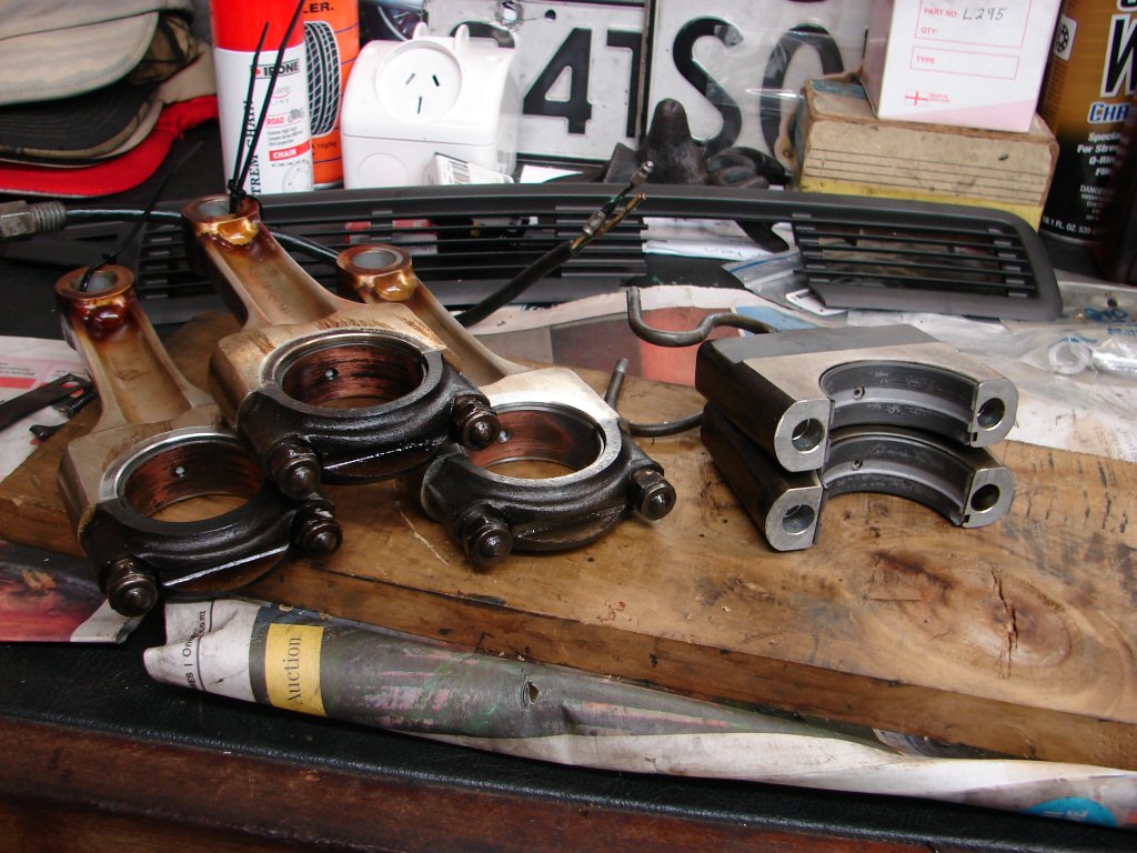
The lower main shells do all the work, so they too have lost their lead and are down to the copper base. This is also the first time I have stripped a triple which still has its cam follower oiling pipes in place on the main bearing caps. They were done away with fairly early in the piece as these will now be. I think the fact that the triples thrive on revs made sure that everything inside got plenty of splash. I have always ridden any triple using 3000rpm as the minimum engine speed, and mine is still on standard bearings and cam gear after 64000 miles. Best not to dawdle...
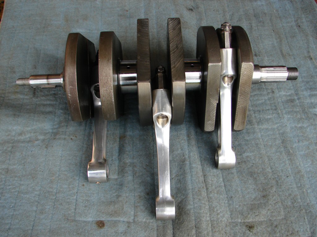
The crankshaft looks to be in very good shape, and if by any great luck it does not need grinding I still have sets of copper/lead main and big end shells amongst my stock. This would be a wonderful new home for them.
I will make another observation. In both this engine and my own, which I first stripped at 41000 miles, while the bearings were down to the copper, the crankshaft journals had survived in very good shape. I think the now scarce copper/lead shells were more forgiving as well as longer lasting than the current white metal type. Yet another diminishing quality trend. My T160 is 20 thousand miles into its second set of copper/leads on standard journals and runs excellent oil pressure still. It would be great to secure the future of this engine with some too.
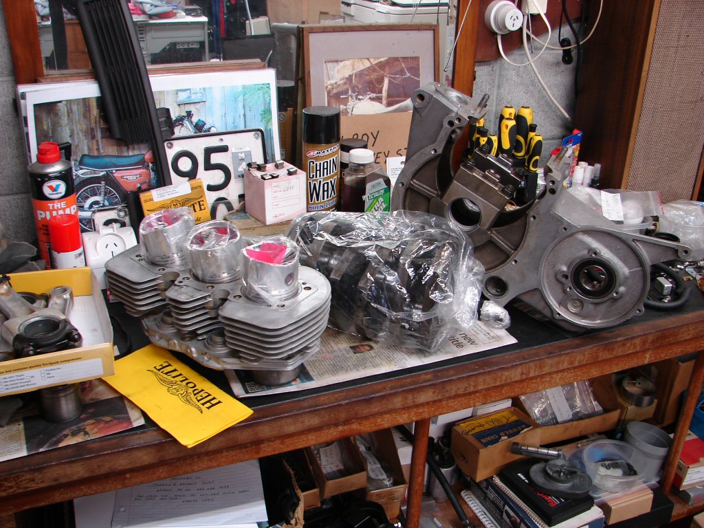
The crankshaft, barrels and pistons went off to Glen for measuring. I'm guessing +.020 rebore and pistons, but the crankshaft I remain hopeful that at least one set of journals will not need grinding. That would be a great saving plus a better result. Whatever the outcome, it will enable the first major order of parts, while they still exist.
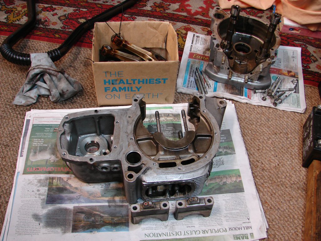
Meanwhile the cleanup begins - a least favourite job but a very necessary one. This includes running taps and dies over every thread so that nothing is left to chance during reassembly. Yet another first - no less than three of the barrel base studs were loose in the crankcase, and one came out with the nut still captive. Not seen this before.
The cam follower oil feeds needed to be removed from the main bearing caps, and I did that by cutting the pipes off flush with the base and fitting blanking screws into the part of the pipes that is cast into the alloy cap. I have seen some hideous versions of crimped pipes etc in order to do this job, so am rather pleased at the tidy result.
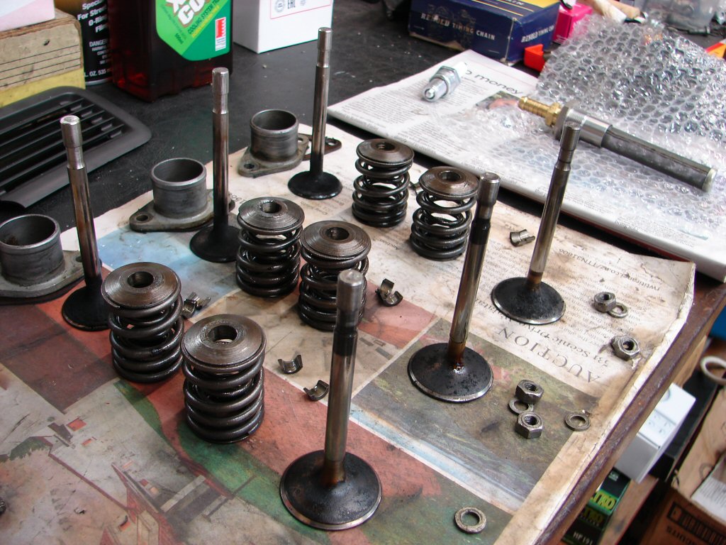
I finally got around to stripping the cylinder head. I suspected that it had received some attention since birth as the valve stems looked kind of shiny, and while there was a good carbon deposit on the back of each inlet valve head there was no wet oil. Sure enough it has already received a set of valves and guides at some stage, but the guides are the type which use seals, and there were none, so the worst of both worlds really.
Also the valve stems have worn badly already, so it shall get new versions of both. My supplier is out of early inlet valves which are longer than later type, and thus use short adjusters. The bike has mushroom adjusters fitted, which have worn the ends of the stems in a pronounced fashion. The later long adjusters featured a flat sided ball-in-socket adjuster which floated far more easily across the valve stem than these point-contact type, and as I have a collection of such things, I am considering buying short valves and changing the adjusters. They are a bit more fiddly to set clearances on, but do a better job in my opinion.
I removed the oil tank filter to clean it, and found a hefty deposit of the same black sludge as had been in the primary case in the bottom of the oil tank. The filter too was well coated and took a good scrub to clean. That prompted me to remove the oil tank from the frame as it will be much easier to clean by swilling some kero around in it.
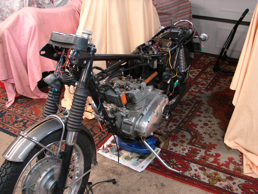
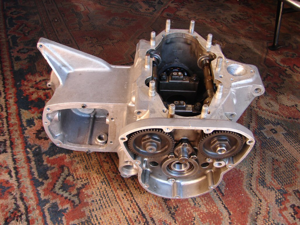
This leaves us with pretty much a bare frame right now, and while it is not the most flattering look, it will make the imminent rewiring process a lot easier. That is at least one task I can complete while waiting for engine parts to be machined.

There is no substitute for cleanliness when reassembling a new engine build, as any engine reconditioner will agree, as that is drummed into them during their apprenticeship. While one can hardly disagree that all the new parts are going to make most of the difference between before and after, a small amount of grit left in the system can immediately age a new build by thousands of miles life expectancy, and I know personal accounts of it being catastrophic.
As critical as it is, I have great trouble being enthusiastic about the process, not having a cleaning bath and all. It is just one of those necessary steps along the way, and helps to fill the time while waiting for the outwork to be done.
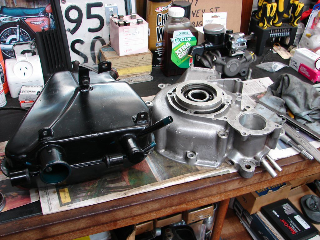
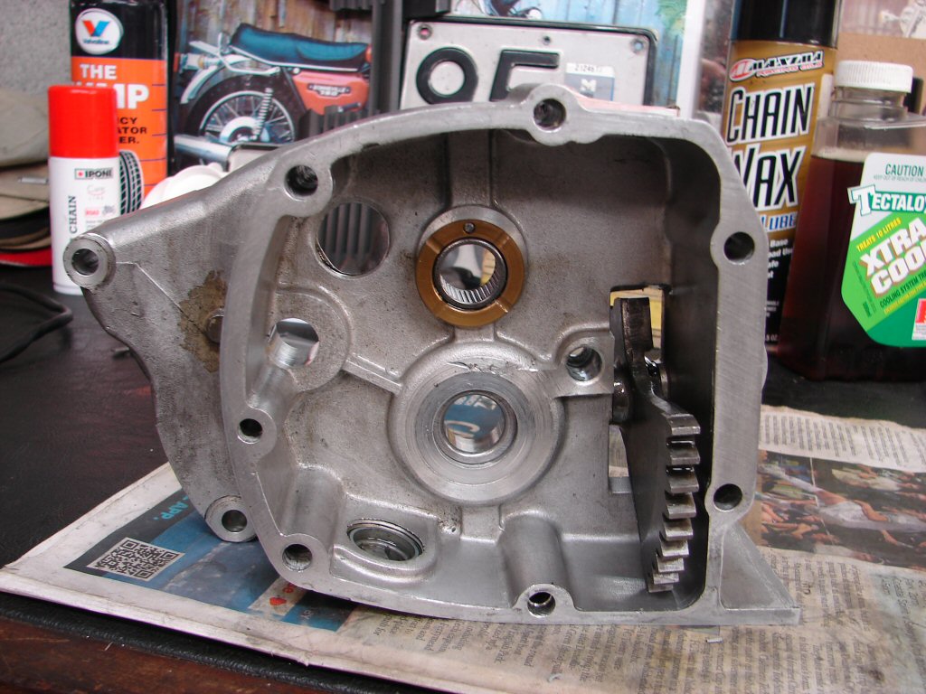
So far oil tank majorly degunged and drive side outer crankcase cleaned and repaired and now awaiting a new main bearing when it gets ordered. Interesting to note that the oil tank began its life on an aquamarine UK styled machine before receiving its 'beauty kit'.
As I have two more triples arriving tomorrow, one already in parts, the cleaning cases process had to speed up just to create some more space on the floor. Many of the threads were partially blocked with old sealant and the occasional protruding thread, so taking care of all such things now means no backtracking during assembly.
It appears that the original chain oiler may have still been in use to some degree, but as the clucth housing was in a hideous state and the chain was naff, there is no doubt that purpose made chain lube is definitely the way to get long life from the chain.
As the wiring process has now begun I refitted the oil tank and coil platform, as that is where many of the wires will go, so it serves as a guide to positioning the loom.
It is always a milestone when the first parts actually get bolted back on, so it seems as if we have turned a corner, despite there being nothing to assemble in the engine dept yet.
At an early stage of T160 production the oil feed from tank to crankcase got uprated in order to encourage better oil supply especially from cold starts. While it is not a huge job to make the mod, it requires the crankcases to be in bits, so it is usually a spin-off of a comprehensive rebuild.
As we are now doing one, this is pretty much a necessity in my book, and as I am doing one I shall do two, which means that as the precision part of the job requires honing the crankcase to effect a good interference fit for the larger pipe, and thus a degree of setting up for Glen, it makes sense to give him two at once.
The early T160 case on the right has already been drilled through to where the oil pump lives, and I am removing the old pipe from this engine to do the same. Glen will then only have to hone and fit the new pipes to both, which change from 5/16" to 3/8" and make quite a difference in flow rates. I also encourage the use of synthetic oil once an engine is run-in, as it too flows better when cold than an equivalent viscosity mineral oil, so its a win win.
Not only did this bike still have the small pipe, it was also bent, and I had partially straightened it in order to get the clips on the oil hoses undone before lifting the engine out.
The oil tank filter also has to be drilled out and a larger pipe fitted there too, but that can all take place off the bike.
I am in the process of delivering another set of engine parts to Glen for his attention, and while I understand that he is fielding a huge amount of work, he is starting to make noises about getting onto my stuff, so that will be a big incentive to get on with the other things that I can do meantime.
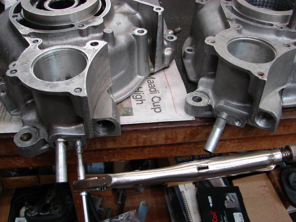
Before and after pics of the two crankcases I have been working on. The hole in question is at about 4 o clock position and the difference in diameter is clearly visible.
It is now on a par with the hole that feeds oil to the engine bearings, so the difference in flow will be significant. The third 5/16" hole is the scavenge side which returns oil to the tank from the bottom of the crankcase, but as it has larger gears inside the pump it will always scavenge faster than the pump can deliver. Good thing that..
As fortune would have it, Glen phoned today and gave me all the measurements so that I can now make what will hopefully be the final parts order, so I carted these cases in to have the larger feed pipes fitted in a precise manner.
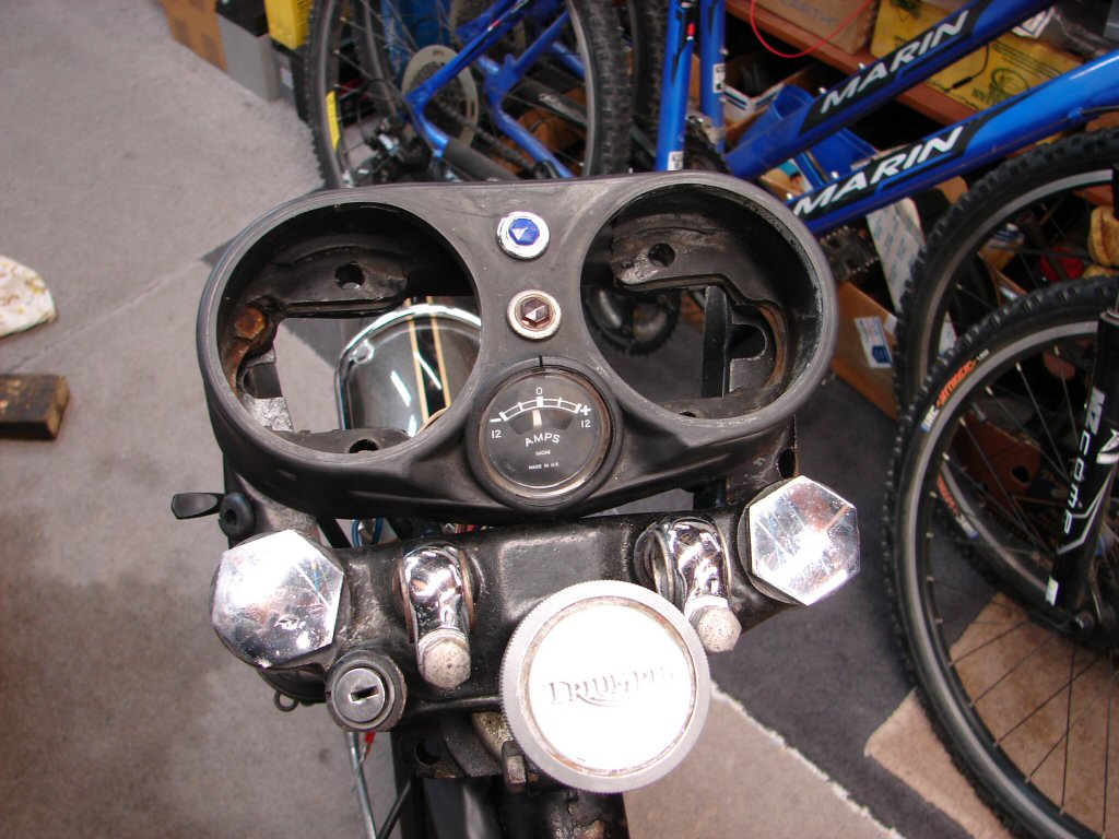
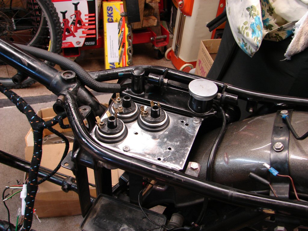
Now the focus is the new wiring, and it had become necessary to remove the headlight to gain access beneath the clocks, as well as to refit the ammeter into its housing as it was sitting a bit proud. All attempts at getting it lower from the top had given no success, so I removed the clocks to achieve that plus because the earthing connections for the panel lights are included in the new loom, and they are clamped under the mounting bolts.
The ammeter pushed in from underneath with consumate ease, which was a relief as it seems to be a plastic replacement rather than the original metal case job.
The absence of the clocks will also make arranging the wiring inside the binnacle much easier. I identified which were the + and - terminals on the ammeter so that it reads the right way, and looking at the back of the tacho I found one internal retaining screw missing and one about to leave, so that was timely.
I was pleased to find that despite the new loom being supplied as for 1969 models, it does feature wires for indicators which these models did not have, but this bike has had subsequently fitted. Makes life much easier when all the wire colours agree with the wiring diagram too, and many extra wires that were fitted when the bike arrived can be dispensed with.
The loom has now been positioned to best effect due to the various branches which feed specific devices. The sidecover got fitted to make sure that the cover goes on and off in future without colliding with the wiring loom.
As the bike now features a solid state rectifier/regulator and a black box Trispark I shall have to get creative about where everything can fit with the least problems. The original horn relay - sourced from a London bus by the looks - has already been replaced with a modern type by the previous owner, and may be able to move to the underside of the coil tray in order to fit the delicate bits on top. Only way to find out is to do it...
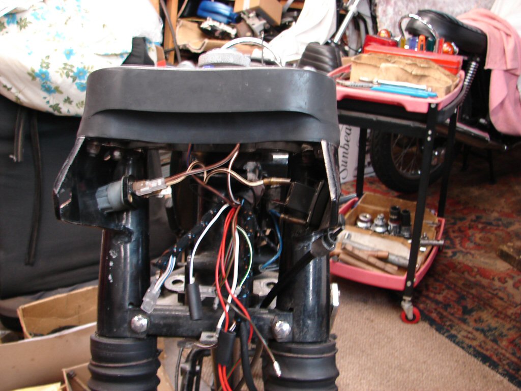
In order to connect all the wires behind the headlight the handlebar switches need to be in place. However, there are new 'bars to be fitted, and doing that required some work on the mounts for the handlebar clamps. The original setup was missing some parts which make the 'bars firmer in their mounts, doing away with the disconcerting fore and aft play that is more common than not. Assembling the spacers and hemispherical washers must be done one way only or the whole plot waggles about. This one had been missing half of the correct parts altogether. Now sorted.
The new handlebars will require a bit of careful fiddling due to there needing holes to be drilled for the horn button/dipswitch. The addition of an indicator switch has necessitated a bit of juggling for position.
It is always a split decision when rewiring from scratch with new loom and new components like electronic ignition and rectifier, where everything will end up, and will the loom agree with the plan. Consequently you have to do both in your head before committing to it. While the connections behind the headlight are still to be sorted, I need to know which wires mean what under the seat so that a meter can be used to prove continuity to each device.
For this reason I did a rehash of everything under the seat today, and laid it out for the loom to be positioned as close as possible to its intended target.
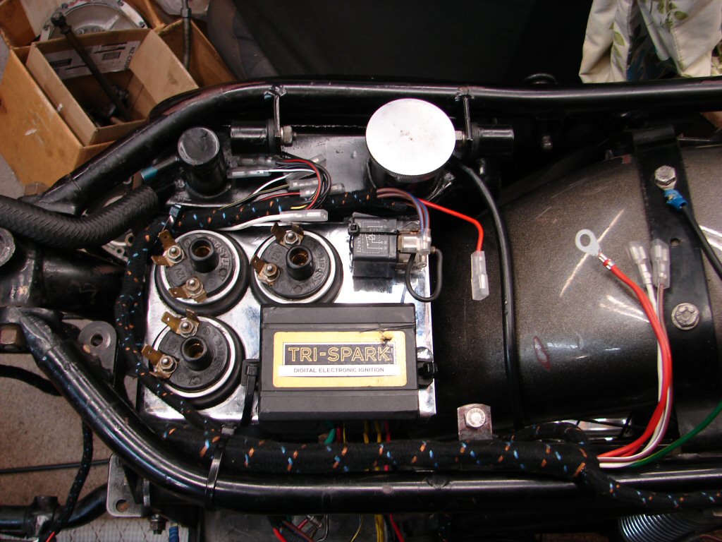
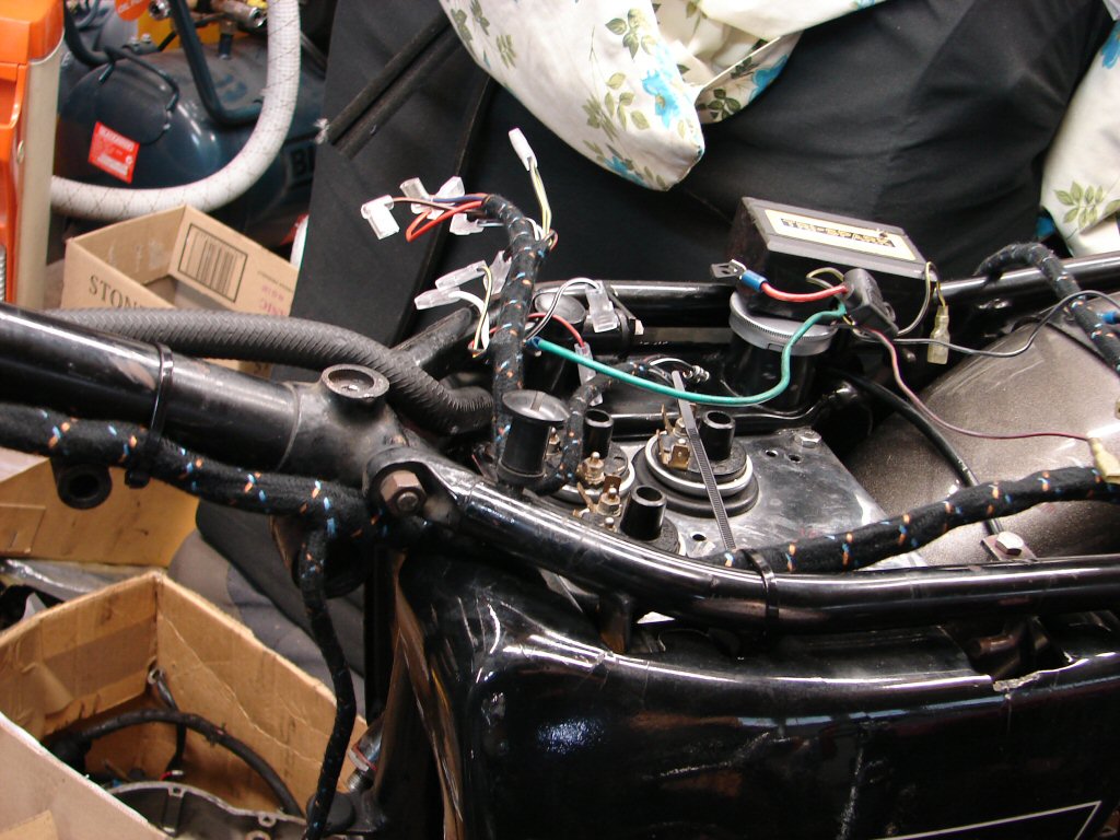
The rectifier ended up being the one moved beneath the tray, as it uses the tray as a heat sink to prolong the life of its internal components so a good flat surface is best. Its wiring now emanates below the Trispark box and the loom connections for the original rectifier are immediately to the right sitting on the mudguard, so very handily placed.
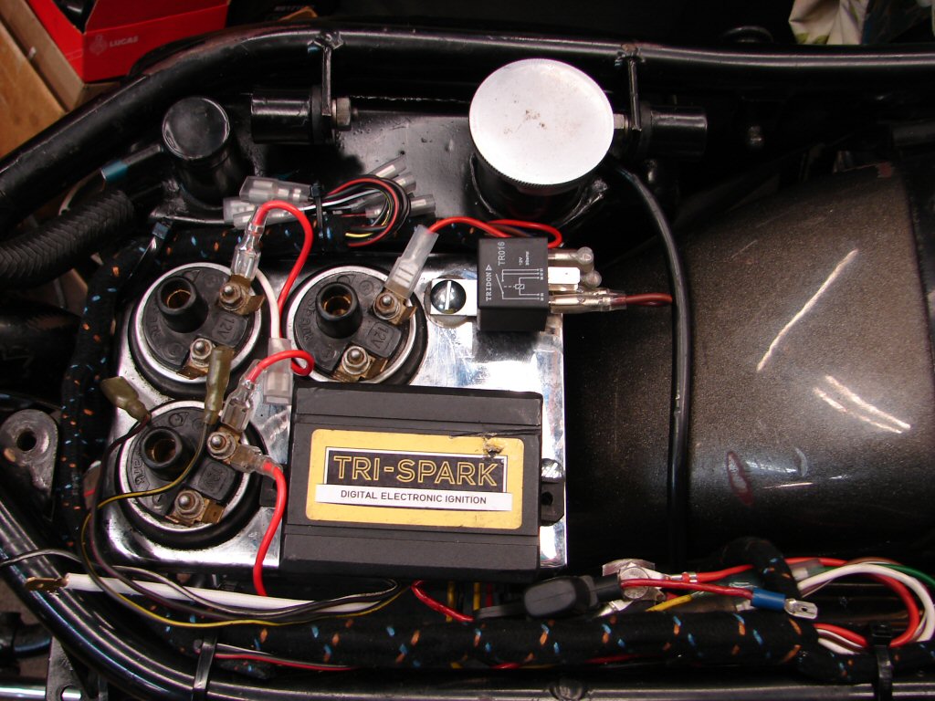
Likewise the loom's horn relay wires ended up right next to the oil filler cap, which suggested the best position for the relay. The Trispark pickup unit where the points used to be has its own loom which will hopefully be long enough to reach the box, but will easily be extended if not. That will have to wait until the engine is in place, but everything now has a location for its related wires to go to.
It is all quite logical really, but a bit of planning helps avoid time consuming rearrangements. As the Trispark had to sit on some bolt heads I mounted it on a piece of foam rubber and retained it with cable ties which are easier to cut off and replace than bolts are to unscrew, and as the entire box has to be upturned to make the connections it is going to come off at least once. The horn relay also got the cable tie treatment as it can vibrate enough to shake its innards loose if too firmly mounted.
I am thinking that there might have to be an earthing point near the relay for the horns to use, so perhaps one more hole for a stud is required.
Dang.
Having completed as much wiring as can be done without the engine in place it was time to test it. I have a sealed beam headlight from a car with a pair of wires attached, which I can use as a "load" when testing 12 volt systems. I wired this in series with the battery so there would be no fuse blowings should a short circuit show up. It didn't, but I found a few failed pilot lamp bulbs to replace. I also found that the horn relay as fitted is permanently on, as seemingly the contacts have fused themselves together. This meant a new relay had to be fitted, and as it had a steel lug for mounting I fitted a nylon spacer between the two surfaces which will insulate the relay from the worst vibrations.
All the lights, indicators, switches and brake light worked as intended, so I am happy with progress.
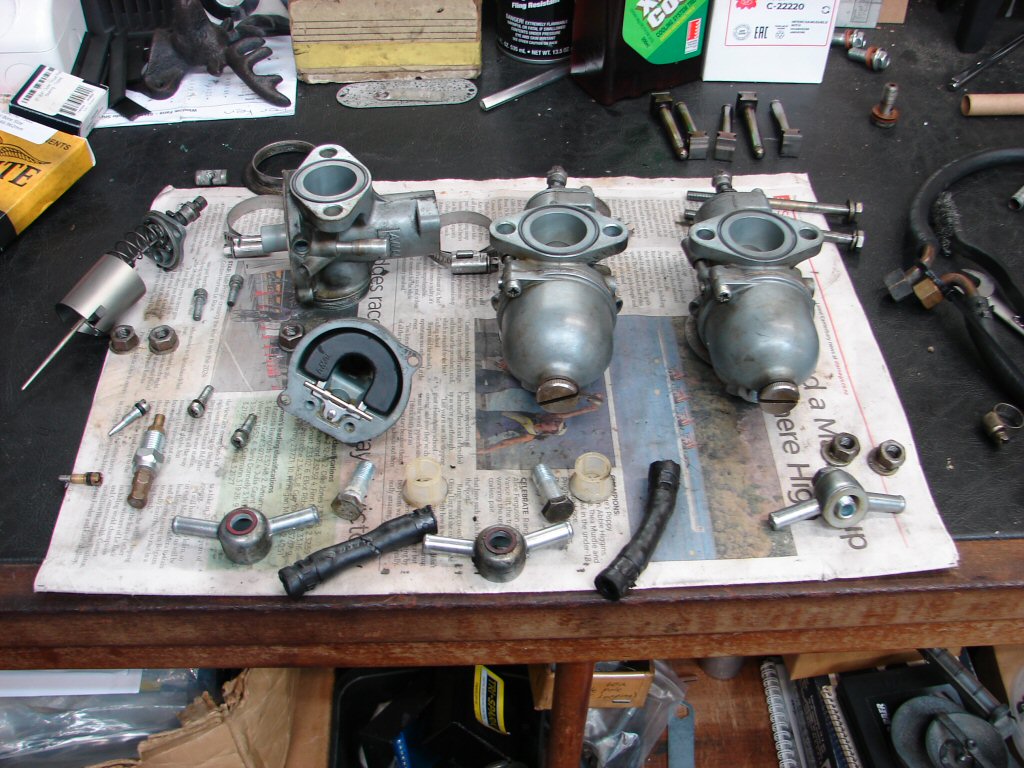
One of the assemblies that need attention before going back together is the carbs. Some of the hoses were staying put by more good luck than management, the chokes were not needed so can be removed to make everything easier to operate, the return springs are gorilla material and there is a fair bit of corrosion in the bottom of drain plugs and likely the float bowls to be cleaned, thanks to our chemically modified fuels.
So the battle began today, although I did not make much progress before being hijacked. Removing the chokes simplifies the whole setup while replacing the return springs with the lighter T160 type takes a great load off the right wrist. I have no idea how accurate the current state of tune may be, but the changes that will occur with the engine means that it doesn't matter much as it will be tuned to suit how it breathes with the new bits.
As the choke lever is in a prominent position being part of the front brake lever, I will leave the top cable in place to preserve the look of it all.
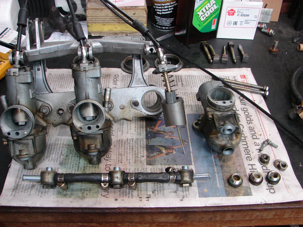
Every single part of each carb gets cleaned, checked and wire brushed during this process. Adjustments are made as parts are revealed, like the float levels adjusted to 1mm below the opposite top edge of the bowl, the needles reset to centre clip rather than top, as this is the factory setting and we have to start somewhere. Choke mechanisms removed and softer return springs fitted above each slide. Jet sizes are checked and corrosion wire brushed off them, after which the drillings are checked to be clear.
The hoses which connect the banjos were removed for replacement, one pulling apart in the process. All the jubilee clips are dispensed with and single-use crimp style used instead. The idea is to future proof these areas for as long as possible, while obtaining a better result than was previously used, and perhaps making an aesthetic improvement as well.
Its a win win win.
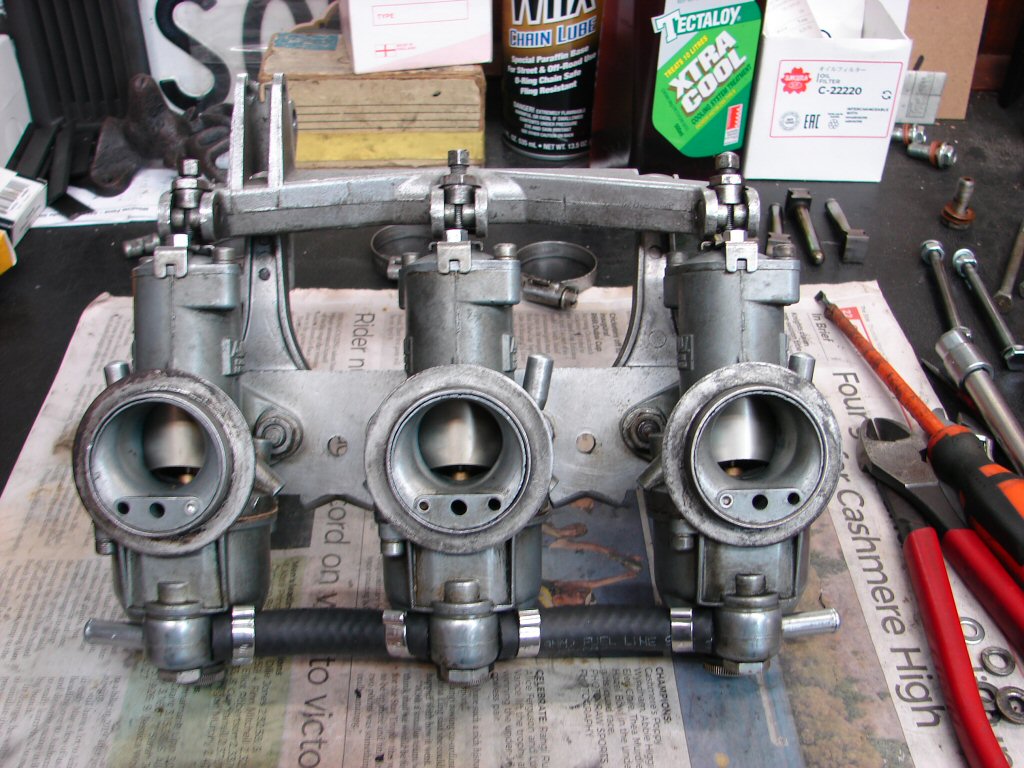
The first thing I had discovered when stripping the carb setup was that all the nuts holding the carbs to the adaptor were only finger tight, which would surely have allowed a certain amount of extra air to be getting drawn in to the inlet manifold. The slides are the correct cutaway of 3½, but I have found that the anodised slides seem to function slightly differently to the original type as far as the cutaway is concerned. It is impossible to predict how it will run when all is cut and dried, but you can only tune it to suit how it presents once running. Being all stock T150 settings, airfilter and mufflers would suggest that the stock settings will work best.
It is a relief when things start going back together, especially as the clean parts are easier to handle and there has not been anything more serious to contend with than two bolts being unsuitable for the job of retaining the airfilter as they are way too long. Usually this laborious job is really just several years of routine maintenance being condensed into a few hours, but now there are no unknowns and everything has been given the all clear. Final job will be to drop a small ball bearing into each intake and set the individual slides so that the three drop out at the same instant. This ensures that the bike will actually run straight up, and the fine tuning will be done with a vacuum gauge once that happens. With the stock exhaust manifold the two outer carbs invariably draw less air than the centre, so I attempt to compensate by guesswork at the same time as the ball bearing test.
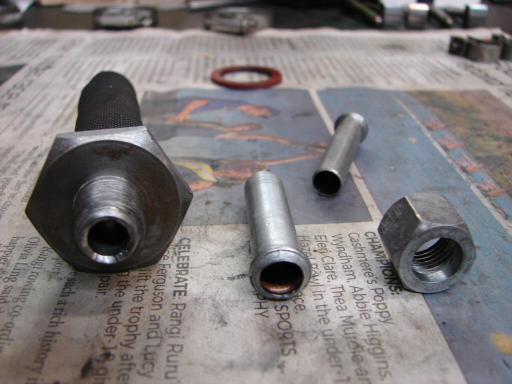
Another prep job involves drilling out the oil tank filter so that it can take advantage of the new larger feed pipe. Because nobody has any stock of T160 filters the stock fittings need to be modified to accept the larger pipe.
Once that is done the outlet from the filter has to be changed from a convex to a concave profile so that the new pipe fits into it and achieves an oiltight fit. Not a huge operation but it involves a lot of increasing size drill bits and thorough cleaning afterwards to ensure there is no swarf left inside the filter.
Feels like a good fit.
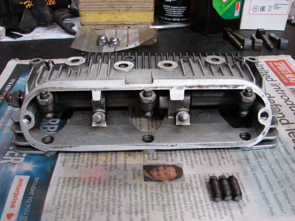
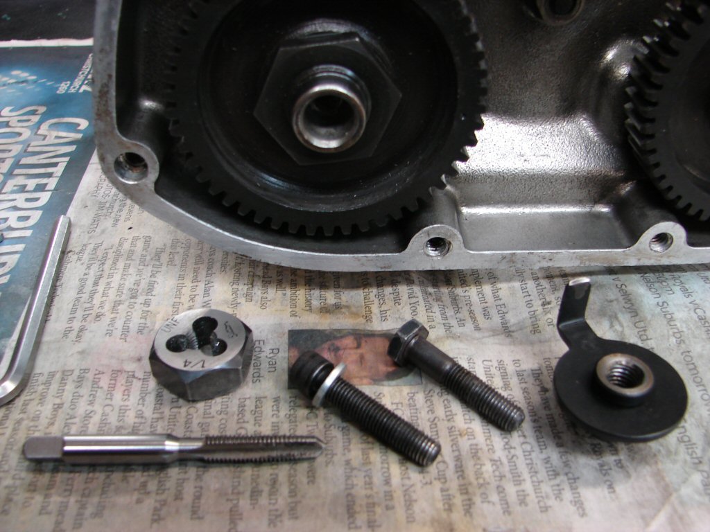
Now the rocker boxes get their turn. The exhaust rocker box had thread problems on the outer inspection cover bolts, and it seemed to have been leaking oil from the O ring end of the rocker shaft, so it got a complete strip.
I thought the threads had been changed from UNC to UNF, but in fact we shall be going the other way. It had been previously helicoiled as the UNF threads had pulled out of the alloy, but the helicoils have also pulled, so the coarser UNC should be a permanent cure.
Spot the missing threads..
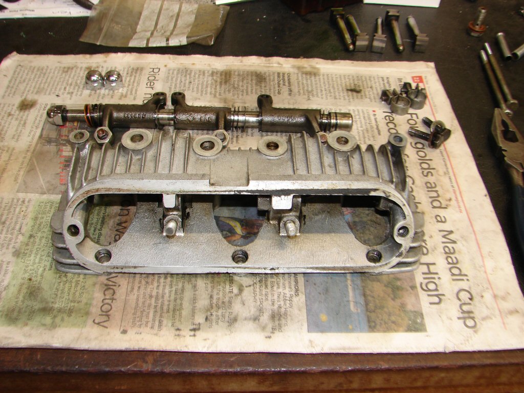
Top right in the above pic are the two oil line clamps which were fitted to the now obsolete 5/16" oil line. I straightened them and cleaned them up as I am hoping that they will accommodate the 3/8" hose, and they are well made and elegant items. They have managed 57 years of service in fine style already, so a few more decades should be a breeze.!
The stripped threads responded well to the helicoil process and all that is needed now is a new pair of bolts in UNC. The rocker shaft went back in happily enough with a new O ring lubed with silicone sealant to be sure to be sure.
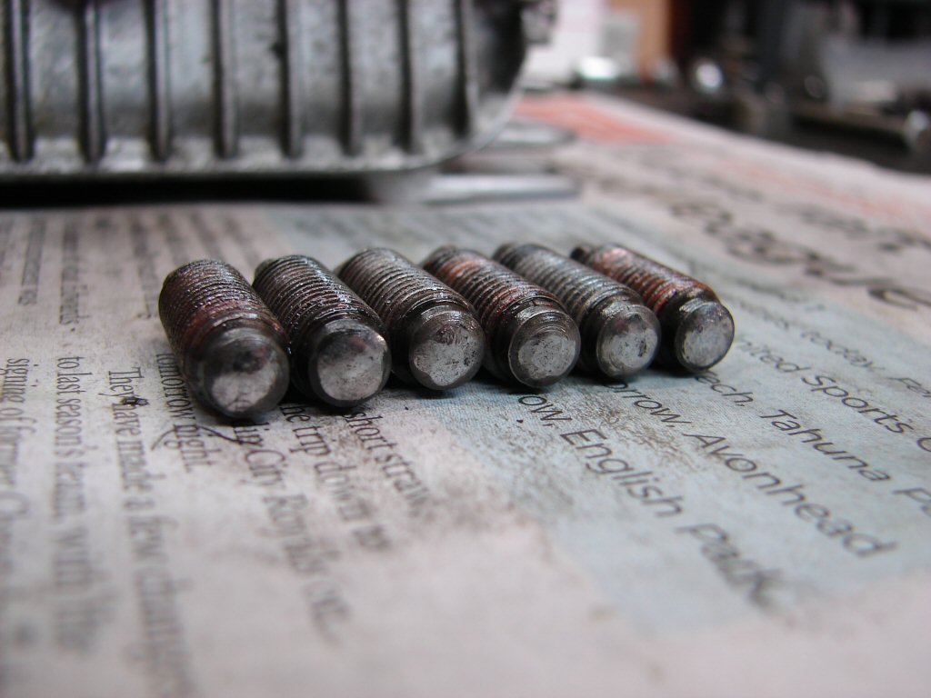
Amongst the spares currently not available have been long stem valves, as used by these early model T150's. To counter that I ordered short stem valves and have changed to long adjusters as fitted above. These are good used examples which feature the ball-in-socket ends with a flat on the ball that is self-aligning to the valve stem and slides easily across it, reducing the side thrust which causes faster valve stem wear. The longest tour of duty my T160 ever managed on a set of valves was with the original adjusters like these.
Having now had a good look at the adjusters that are being replaced I am rather pleased they are coming out. They look like they have had a hard life.
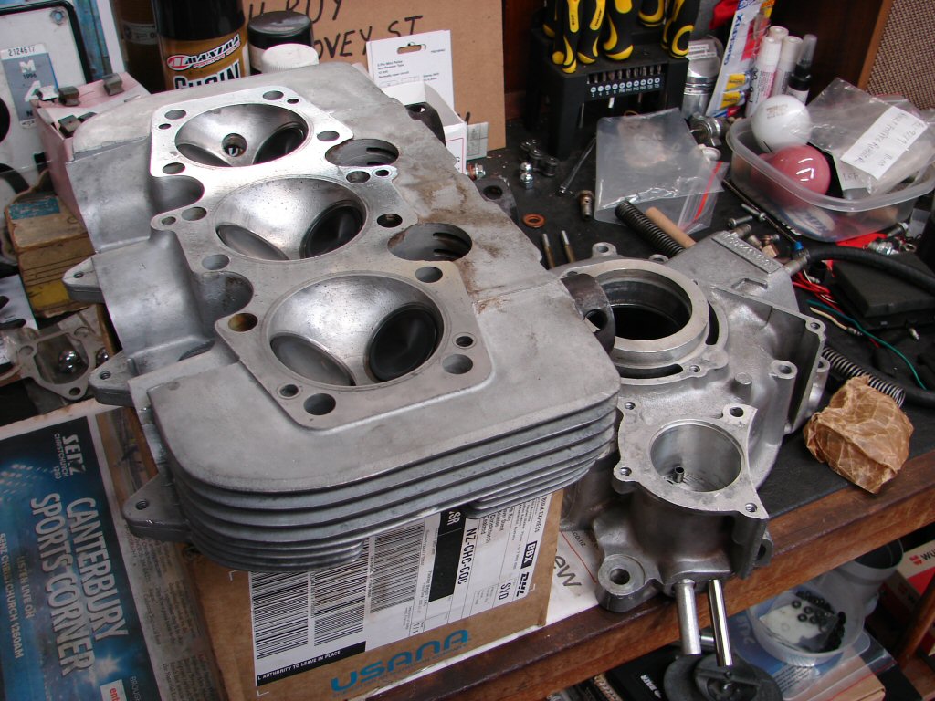
Glen phoned to say the head and crankcase oil pipe jobs were complete. He also required the new engine bearings along with centre crankcase and conrods, as the crankshaft is about to be ground to the clearance size needed for what we have, rather than what the factory specs say we should have.
So I cleaned up and fitted the shells, torqued them up then took them in, and returned with our first finished bits. This allows me to finish assembling the valve gear so the head will be ready to fit.
While the cleanliness of the combustion chambers are obvious, the insides of the inlet and exhaust ports are also exceptionally clean, which saves me a messy job. Top work. I have a suspicion that Glen understands my obsessive nature with engine builds, and that may be a very good reason why he takes so long to finish to my standard. He need not worry, as his standards are no less demanding than my own.
All the valve spring assemblies got fitted today, along with the inlet manifold stubs after they got all old gasket material cleaned off. The gaskets feature a heat insulator between two normal gaskets, and the latter are supplied with the gasket set.
After running a tap down all the threads I used the later type allen screws to retain the stubs rather than the original studs and nuts, as these leave more room for the inlet manifold rubbers and the whole arrangement is made easier to fit or remove. Perhaps that is why they made the change...
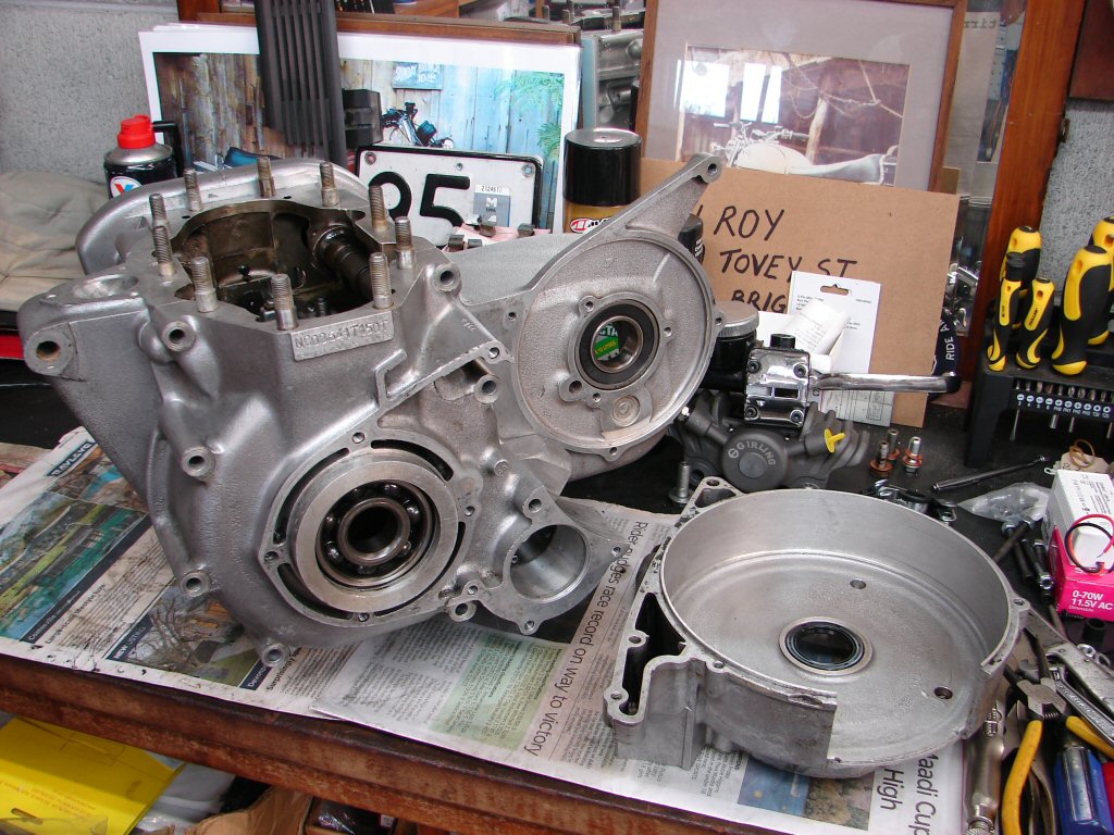
Yahoo - all the engine parts came back today, so we are back in the assembly business. It all looks as you would want it to, and the crank was ground to suit the new bearings which were already fitted to conrods and centre mains.
There is still some final cleaning of oilways to be made, lest some grit got in somewhere during the grinding process, and after that the new outer main bearings will be fitted to their respective cases and the crankshaft in the case of the roller bearing on the timing side.
First step is to check that all the conrods fit up nicely and have a firm but free to rotate relationship with their newly ground journals. They all passed with flying colours and are thus happy with their new old stock copper/lead bearing shells - a rare commodity in this day and age, but the best option for a long service.
While the beautifully machined crankshaft derserves no less, the rods are not polished for a beauty contest, but to relieve any small surface issues which could develop into a stress fracture at a later date - they are 57 years old after all.
So the shiny appearance is just a nice side effect.
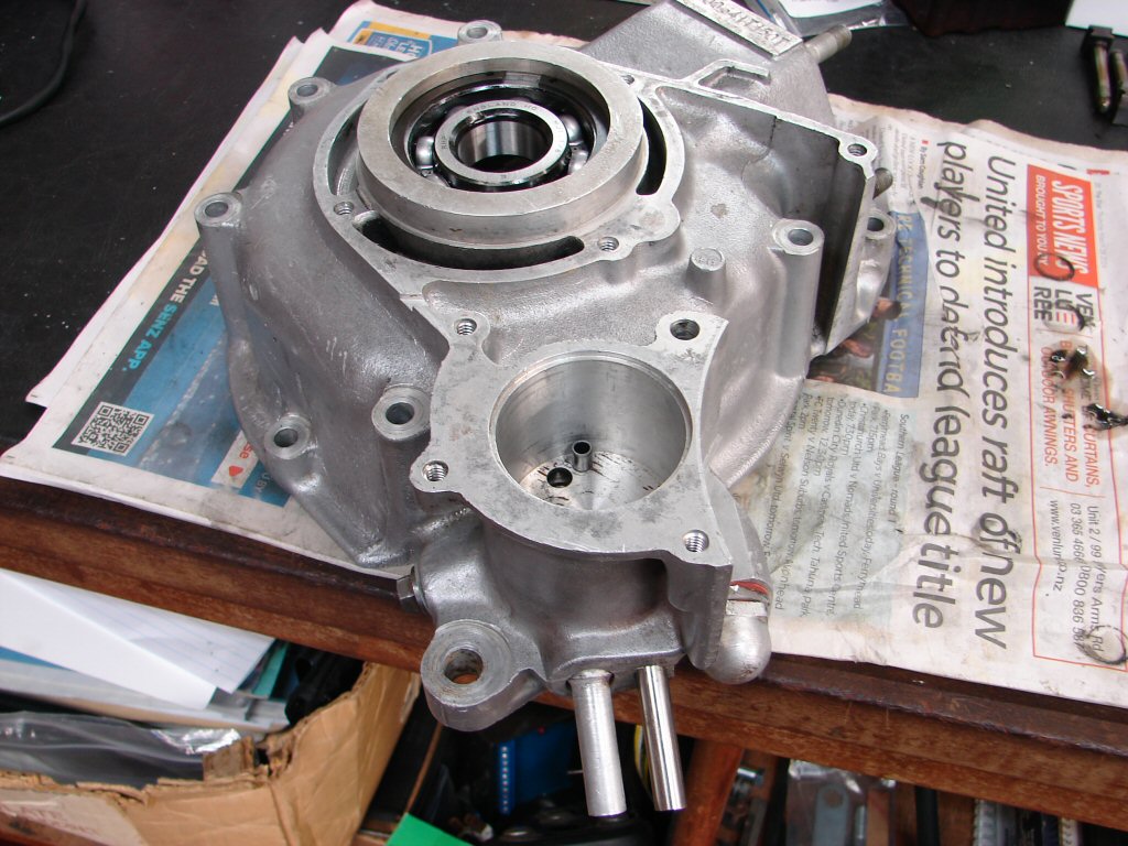
I know I repeat myself often, but you do have to look at absolutely everything during an engine rebuild as it is the best form of insurance that your money will not be wasted due to a problem you failed to see coming. These are the oil pressure relief valve and the anti-drain valve. The larger assembly uses a proper piston and strong spring which allows oil to pass by above around 85psi. As the engine was hard pressed to achieve even 60psi when cold previously the valve has probably been idle for quite some time and needs to be examined for its continued viability. Pleasingly it checks out fine.
The smaller assembly uses a lightly sprung ball bearing to prevent oil draining into the crankcase while the bike is not in use. Unfortunately the machining of the seat the ball rests against is very often flawed, so results are seldom reliable. The adoption of a sump plate with a drain plug, such as this bike has, makes it easier to drain any excess oil and return it to the tank before resuming service after a long layup if it can be seen that the tank has emptied.

Those parts got refitted to their outer crankcase section with a bit of oil to ease their return to service. The only other thing to do to this case before it gets added to the rest of the crankcases during assembly is to fit the new main bearing. As this is the drive side a large ball bearing race is used and lasts for a very long service life as long as it does not receive too much debris from the primary drive, as the oil can travel to and fro in use.
My approach with all ball and roller bearings when going in or coming out is to heat the alloy housing with boiling water first then drive them with a suitable drift. This bearing is retained by circlips, so with the inner one fitted the bearing gets driven in until the top circlip groove is clear enough to accept its circlip. I had also placed this bearing in the freezer for 30 minutes for that fraction of extra clearance and it went in without excessive force, but enough interference to reassure that it will stay put under wartime conditions.
So here we are with all of the above complete - looking good to me.
I then cleaned up all the bolts which attach that outer case to the centre case, which will happen with the cylinders perched above the centre case and the pistons already in the bores, so the outer conrod bearings can be torqued up before the outer cases join the mix. I tried this method for the first time on the last engine assembly after finding that the current oil rings were extremely difficult to coax into the bores, so the idea of trying to do that while holding the barrels in midair seemed like a recipe for broken rings. To my surprise it worked so well that I decided it would be my method from then forward. I intend to fabricate a pair of wooden spacers to fit between the cylinder base and the top of the centre crankcase instead of it sitting precariously on top of four sockets which was my improvisation to keep the cylinders above the height of the crankcase studs until the two outer cases were in place.
I have not heard of anyone else using this method before, but it makes for a far more controlled operation unless more compliant oil rings are used.
Now the replacement of the timing side roller bearing outer race happens, after the boiling water treatment. I have a selection of drifts which suit most of these bearings, but of course one needs to take more care of the new bits going in than the old coming out. The old race is out here and the inner circlip is fitted in preparation for the new outer race to enter the fray. I shall use a gas flame this time as I do not want any water to contaminate freshly oiled camshafts.
I take the process of fitting bearing assemblies into alloy housings with considered care, which includes having the time to prepare and operate without interruption, which often means that I suffer several days of down time before getting back to the job. As this is by far the job I prefer most it can be quite frustrating, but the work I have to do keeps me from the work I should do, which keeps me from the work I want to do.
So today I got to the latter, and after freezing the new outer race and heating the case, the new race went in until flush with a medium amount of effort, then using the old outer race as a drift went fully home against the inner circlip nicely. Even better, the old race which had now partially entered the case came back out with minimal persuasion. This I consider a win.
If one has any doubts about the process after it is completed, one is in for a trying sort of day from that point on...

While this case was still on the bench I checked the fit of the Trispark rotor into the exhaust cam, as the retaining bolt had a few stressed threads at its inner end. I prefer to use an allen screw such as are usually supplied with the kit, but this had an ordinary bolt which sometimes means the original was not long enough. The machining of the taper within the cam can vary from one engine to another, and this is why there is a minimum clearance specified in the Trispark fitting instructions.
Having samples of both types of bolt I tested both, and either seemed ok to do the job, but both had similar thread damage so all three threads will get a clean up and I will then choose the best option.
Having cleaned up all the threads I found that the allen screw would not bottom out in the internal thread before beginning to pinch the rotor, which means that as I am going to use a sturdy washer in the mix as well, there will be no danger of that happening.
I have previously suffered a breakdown during a test ride when a rotor such as this came loose. It did so because the thin washer which had been used was able to dish itself into the recess of the rotor housing, so tension was lost and the rotor began to slip. Thus, a serious steel washer should be used, such as the one in the pic.
Satisfied that that there would be no issues here at assembly time I moved on to trial fitting the crankcases together. The two dowels at the top of each side outer crankcase generally succumb to corrosion, and as they are a very neat fit into the centre case they can cause no end of bother either fitting together or having to come apart. I had given them a good polish and they were pleasingly firm but compliant.
Any discrepency with these dowels can lead to there being a non-uniform surface for the cylinder block to seat on, encouraging leaks amongst other things, so they are a vital part of the puzzle to be aware of. All good here.
Next step would be trial fitting the crankshaft into the centre case and bolting the main bearing caps down to ensure the clearances were accurate. The early engines such as this used self-locking nuts for these caps while later models changed to locking tabs, as not all self-locking nuts remain locked. This trial fit would include making sure that the new parts mated up happily.
As I tightened the new non-locking nuts down I encountered a bit of resistance towards the end, which I assumed might be because without the original thick washers they were encountering some previously unused thread on the studs, so I took them off to see.

While the later bearing caps have a flat surface, the early ones are raised in the centre. At a glance they look as though they will accept the locking tabs easily enough, but while the two rear nut and tab arrangements had worked as intended, the front nuts had deformed their locking tabs because the tabs had collided with the leading edge of the raised centre. Any added interference here would undoubtedly prevent the correct torque being applied to two of the most important bearings in the engine, so they would have to be modified.
This is why I do a lot of trial fitting. Parts which are from different models can be forgiven for not playing ball, but unfortunately there is also a reasonably common incidence of new parts which have not been made as accurately as the originals. One of those scenarios had now taken place.
I had to reshape the locating ends of the tabs by filing quite a bit off, and radiusing the underside to fit the caps without interference. After that everything tightened up happily and got moved to the bench for the locking of the tabs to be done.
From there I moved to the cylinder block, firstly to refit all the cam followers and retain them from dropping into the crankcases during assembly, secondly to check the ring gaps for the new pistons.
While I have yet to find a new ring that was not correctly gapped, I have seen the results of what happens when they are not, so it is a necessary process.
Gapping complete, all the rings get fitted to the pistons and the pistons are inserted into their bores from the bottom, assisted by the extended taper that Glen machines during the reboring process. The inside circlip is fitted before the pistons go in and the piston is only moved into the bore as far as the gudgeon pin hole, which makes fitting the conrod a breeze as all the rings have entered the bore. Final step is to then silicone the base gasket to the lower face so that it stays put during the rest of the process.
The big end caps and retaining nuts can be seen behind the cylinders here. These are self-locking nuts and I always fit new ones during a rebuild rather than risk a failure, which I personally experienced after a restored T150 suffered a major conrod failure and came to me for rebuilding. As these nuts really work as intended if fitted only once I use the old nuts for the whole fitting process then swap to the new nuts when the final torquing is being done.
Usual practice is to assemble pistons and rods on the crankshaft then drop the cylinders over them, but having found this method to be far more manageable I am using it for the second time to make sure it is repeatable.
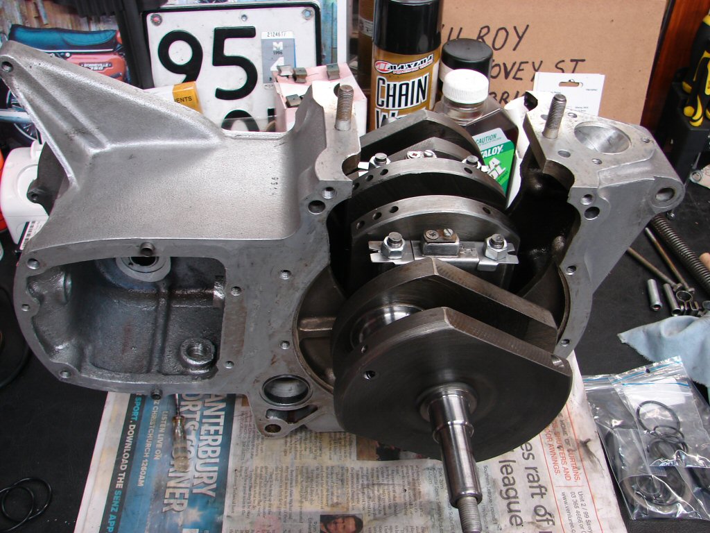
I made the two wooden spacers for the cylinder assembly to sit on while the outer cases are fitted after which they are removed and the cylinders dropped over the studs and bolted to the completed crankcase. As can be seen the two outer rods can have their big ends torqued up at this stage without any risk of the pistons coming out of the bores, and when everything else is complete the centre cap gets bolted up via the sump plate opening.
On the first build using this method I placed the engine on the floor next to the bike at this point because it gets steadily heavier as all the parts join the mix, and the whole idea is to make it more manageable rather than difficult. From being next to the bike it is just one quick lift to drop the engine into the frame once the outer cases are bolted on.
The gearbox, primary drive and cylinder head will all be added with the engine bolted into the frame, which makes the perfect engine stand. It is also just the right height for working from my computer chair, so thats nice...
So the whole plot got moved to sit upon a sturdy nail box next to the bike and before placing the cylinder on top the three big end journals got oiled. After that it was a cinch to bolt up the two outer conrods. Happy with that I removed one nut at a time and fitted the new locking nuts and torqued them up. This was more difficult than was expected because of the design of the new nuts. The early bearing caps have only marginal clearance for a socket to fit, and that is why the original nuts have their flats raised 1/4" above the base of the nut.
Not so with the replacements which are quite short nuts, so I had to resort to a 1/8 drive socket set. If the torque required had been more than the factory 18 ft.lb. I would have been in trouble. I have not struck such a problem before as the later caps have a bigger recess where the studs are.
Anyways - I won.
After that the outer cases each in turn got a smear of silicone sealant on their jointing faces and went happily home against the centre case and got bolted up using all the original nuts, bolts and studs which I had cleaned and wire brushed over the last few spare minutes spent in the shed, as the Alfa needed new front suspension arms which kept me outdoors while the weather held.
With the outer cases attached the cylinder supports are removed and the block gets pushed down the two outer pistons, while the centre rod swings in the breeze within. You can only lower the cylinder to about where you see it as the nuts and washers have to begin their threads while there is still enough room to do so.
After this we go round and round, tightening all the barrel base nuts about a turn each as the cylinder is gradually pulled down to mate against the crankcase assembly. It is a time consuming game as each bite of the spanner only gets about 1/8 turn due to space restrictions, so it pays to have some good music in the background to avoid terminal boredom.
Once the cylinder is tightly fastened the engine gets tipped on its side and the sump plate removed in order to guide the centre rod to its journal by pushing the piston all the way to the bottom of its stroke.
I was rather pleased to have gotten a clear pic of this scenario before bolting the cap on for its first fit prior to the new nuts and torque wrench. I am expecting a bit of a fiddle with the locking nut/socket/torque wrench jiggery pokery, but that will have to wait until the next foray as darkness has come to town. It often pays to start fresh with any sort of challenge - rather than press on when mental focus is waning.
Had to take a pic of the plot as it now stands though. This has been a huge step forward in overall progress with the engine assembly, and after a few hopefully small details which need to be attended to before the engine goes into the frame we are going to be looking well along the way.
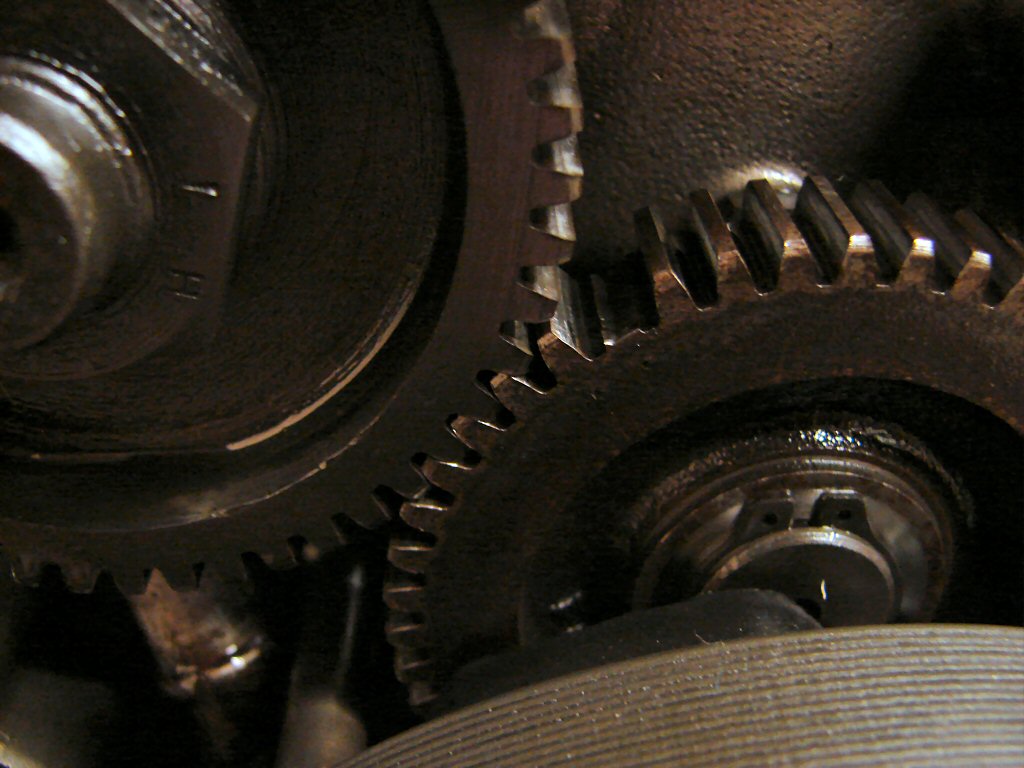
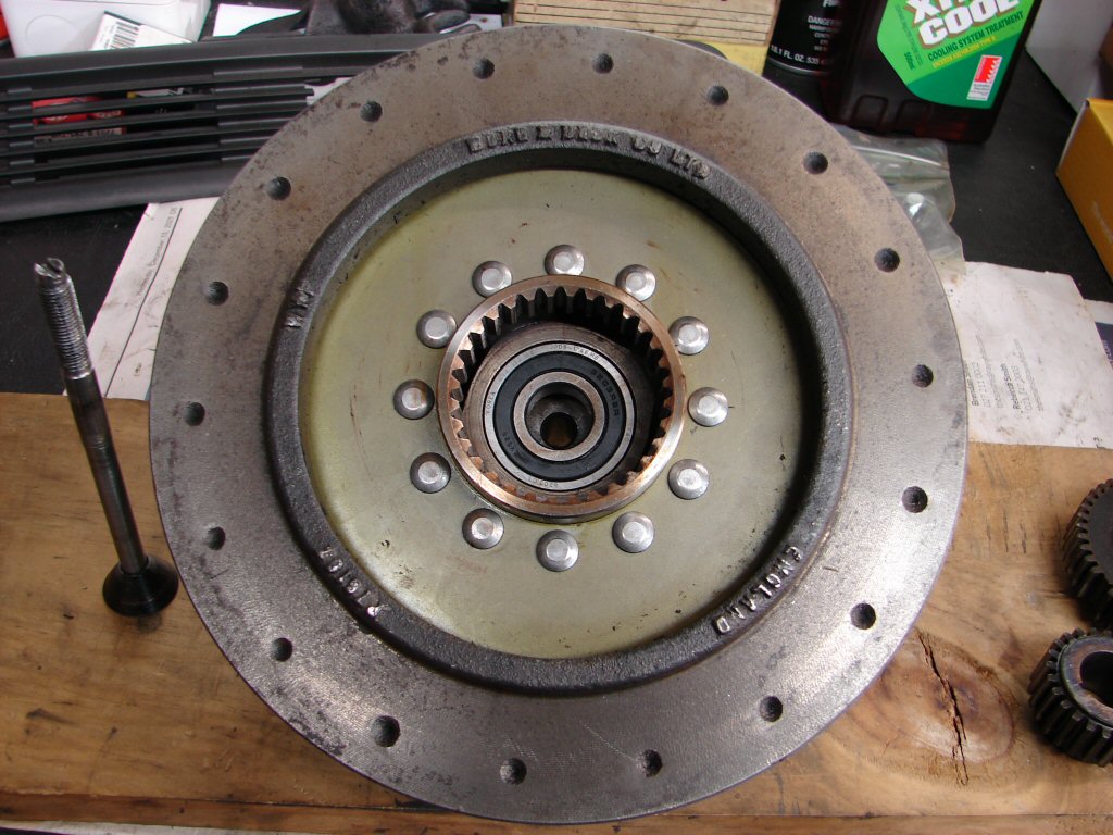
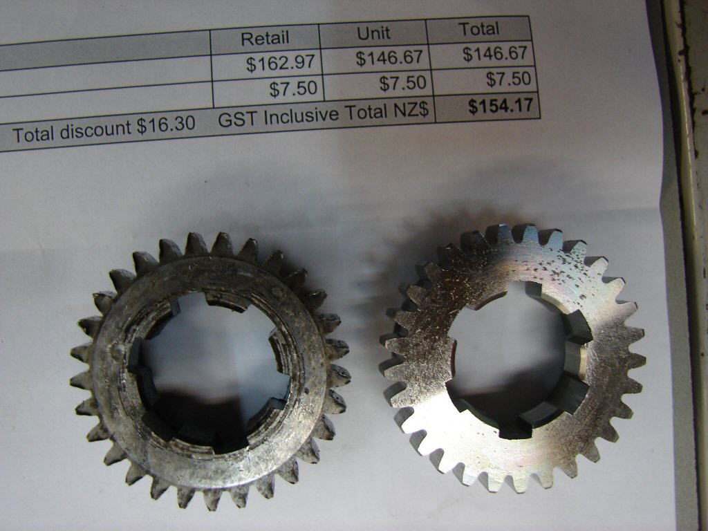
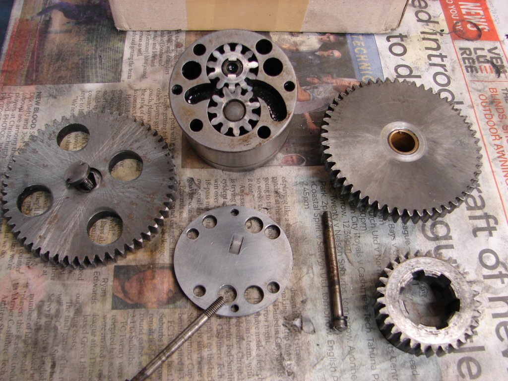
While looking for the parts to go on each end of the crankshaft I gave the two gears a good inspection. I was suspicious that the timing pinion may have either been responsible for, or damaged by the loss of teeth on the intermediate gear. It is definitely worn, but not looking too much so that I would not re-use it. It does however question the recorded mileage of the bike as 22,000 miles should hardly have worn them to any great extent. The real surprise was to be the oil pump drive gear on the drive side of the crank. It is so badly worn that the teeth look hooked in profile. Luckily this crank gear is only half the size of the intermediate and oil pump gears, so they have not suffered anywhere near as badly. The only logical reason for such wear, which I have never seen before, is that the bike has covered some reasonable miles without oil in the primary drive. Usually there is enough oil to ensure that everything inside the primary is well oiled and wear is usually negligible.
This means I will need to find a replacement gear, although I can continue assembling to a certain extent without it. Meantime I stripped and rebuilt the tacho drive which is often a source of leaks, so best check it out before it gets the chance. All looks good and has been refitted, as that is much easier before the engine is installed.
Well, we knew it was coming, but it is still a surprise to reach the point where it is now ok to install the engine in the frame. Admittedly it is only half an engine in its current state of assembly, but it feels like a turning point in the whole game up until now.
I fitted a few more parts before dropping it in, the primary sprocket which I use to turn the crankshaft to and fro when checking the cam timing, and the timing pinion on the other side as it establishes the base point for beginning timing the cams.
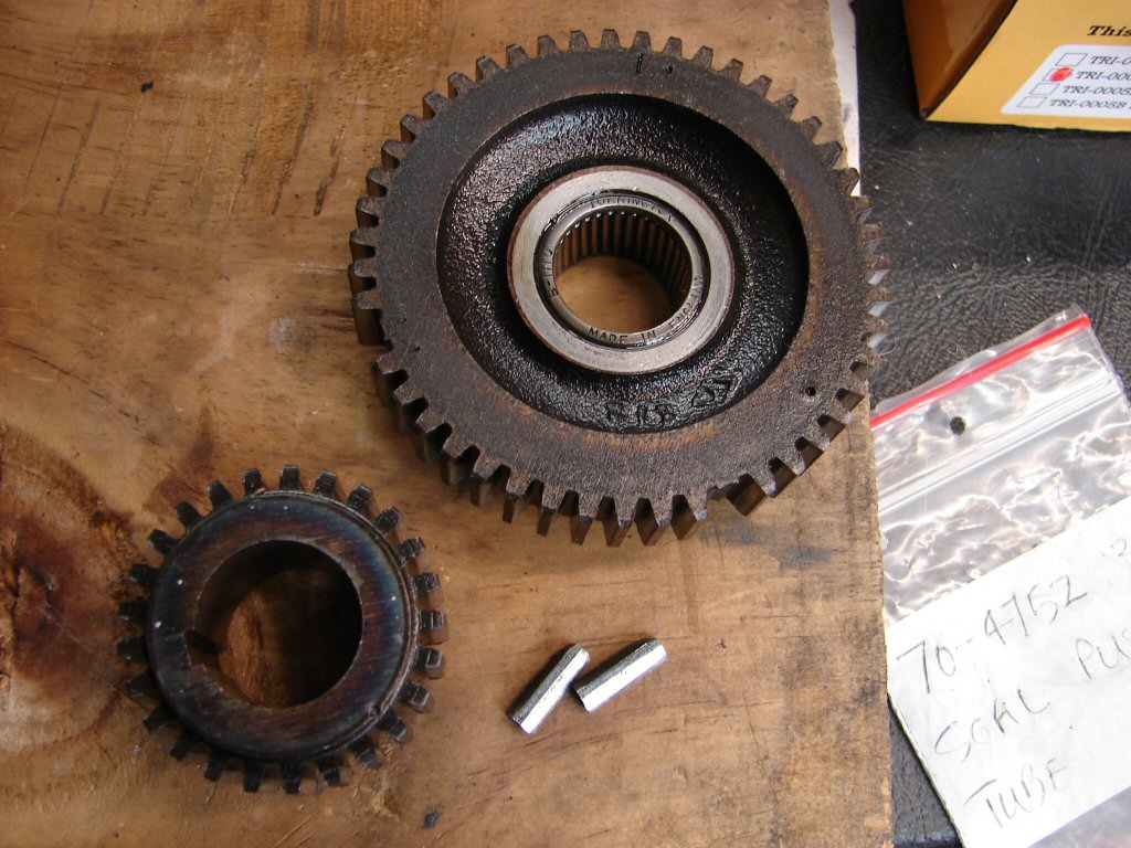
While I used the worn out oil pump drive gear behind the front sprocket, because it is a nice loose fit and will be off and on a few times, the new gear turned up this morning so I took the opportunity to get a pic of the two gears together so the state of wear of the teeth can be seen.
The amount of steel that has gone missing from every tooth suggests that this was a prolonged condition of accelerated wear taking place, and the only reason I can think of is that there was a total lack of lubricant. While the primary drive maintains its oil level via the main bearing through to the crankcase, it would take a very long time to get the necessary amount of oil back to do the job properly if the primary missed out on getting refilled after an oil change.
It is not the cheapest gear you ever bought, but hey - it was available here in NZ and I received it in two days. We are extremely well catered for, which was not the case back in the day.
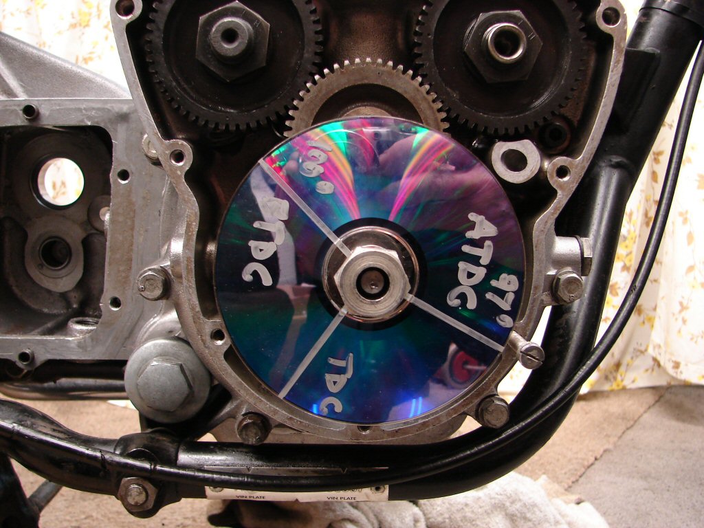
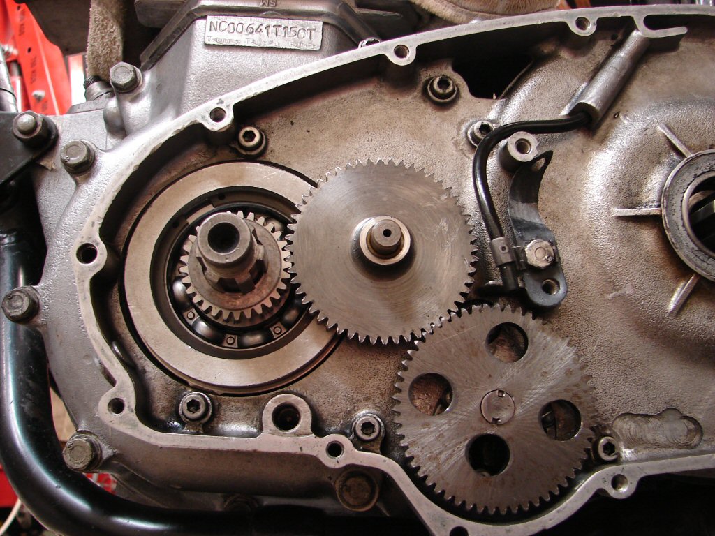
After bolting the engine in place the first job undertaken is the timing of the camshafts. We have a new intermediate gear in the mix now, and while all the gears have timing marks on them, they are interchangeable so you can not risk taking it for granted that they were correctly timed prior to now. I use 'centre lobe' timing to do this job and made up my own disc with only the necessary marks on it.
First we establish top dead centre by rocking the crank sprocket backwards and forwards so the piston can be seen dropping in both directions, then halve the difference to find exact TDC. The accuracy of the method is made evident by being able to repeat the same results time and again. With TDC lined up the exhaust cam lift is now checked for its highest point by placing a steel ruler on top of the cam follower and watching it rise to its highest point. Once again, the rocking to and fro leads to finding the centre point between rising then falling, which means you are at the centre point of the cam lobe operating the exhaust valve. This should take place at 100 degrees before top dead centre, and as can be seen, the existing timing marks gave a result that could not be improved on, as the '100 BTDC' on the disc lines up with the slot in the screw head.
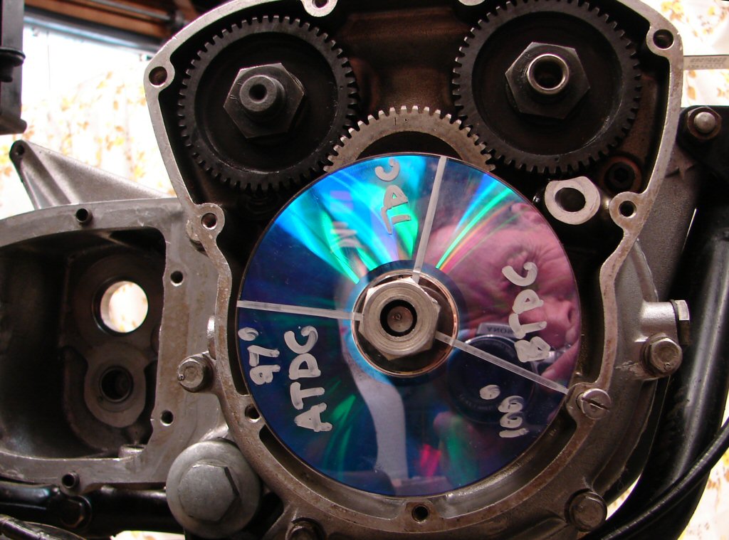
The inlet cam gear has two possible timing marks on the intermediate gear, one being a dot and the other a dash, which is one tooth more advanced. The single dot on the actual cam gear can be aligned with either of these and I have found both being used on different engines. I chose the dot first but had to go well past the 97 ATDC on the disc to reach lobe centre, so I moved the gears by one tooth to the dash mark, and ended up with the cam probably 1/4 tooth more advanced than perfect.
I consider this to actually be perfect, as it is not always possible to get them right on the mark, and I always use the advanced result rather than retarded, if a compromise has to be made. The later T160 Trident had the inlet cam deliberately set one tooth retarded in order to meet the increasing emission standards in the USA, and I perfected this method in order to correct them. I then subsequently found that so many cams were not timed accurately that I now do this procedure on every engine I have the opportunity to do so.
With cam timing sorted it is time to refit the alternator, which mostly involves trying to thread 57 year old rigid wiring through a devious passage in the alloy case. I had to cut the bullet connectors off to do this, but as they are the solder type I can re-use them.
The rest of the process is relatively easy once that is done, though there is a large threaded nut which has to screw in beneath the inlet camshaft gear which the wire also passes through. That seldom provides any grief and didn't this time either. The rotor nut will get tightened when the front primary sprocket is also being done, as one tightens against the other.
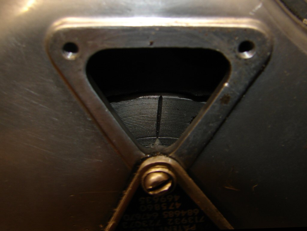
The alternator rotor has different markings on each side. One has the 'Lucas' stamp and a single timing mark, while the reverse has three timing marks to suit the triple.
This does not mean that any of the marks are going to be accurate, so you have to make sure. There is a drilling in the crankshaft webbing that is visible through a plugged hole in the front of the crankcase, whose head can be seen to the right of the alternator at about the middle of it. A philips screwdriver and an eyeball are technical enough to centre the drilling after having set the crankshaft at the firing position of any cylinder.
The timing cover got cleaned up then trial fitted, showing that our timing pointer is spot-on the mark, so using a timing light will make setting the ignition accurately a simple task once the engine is running.
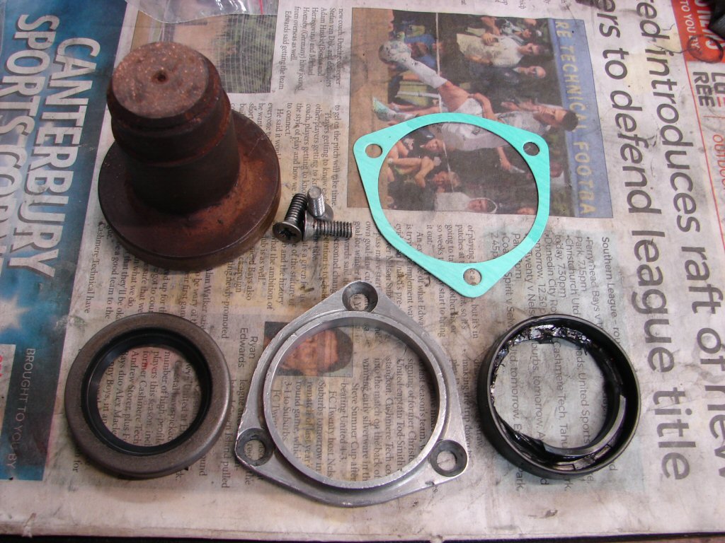
You can never predict which parts of a rebuild are going to create problems, although there are certainly areas that are prone to it. The high gear oil seal is not one of them in my limited experience. As it is the first part which gets fitted during the reassembly of the gearbox I went there first. When looking at it during the obligatory cleanup I noticed that the oil seal and gasket seemed to be in good condition, such that you might be tempted to whack it back on and save yourself some bother. However, we had both new seal and gasket, and the mere thought that we might have to find our way back in this far if it ever decided to leak is sufficient horror not to take the chance. But it just would not come out.
The workshop manual states that the closed end should be pressed in until flush with the outer surface, at which point there should be a slight recess behind the plate as the seal is not as thick as the housing. However, the old seal was in fact thicker than the plate, and therefore was not the correct seal to begin with. I am not sure if it had some form of sealant added to the mix, although I did clean some off the outer edges, but this thing was firmly wedged into a rather slim alloy housing which would crack or deform if you gave it an excuse to.
Using a hacksaw blade I cut through the inner layers until I had nearly gone through the outer edge, knowing that if I did there would be damage to the surface. I then attempted to curl the cut edges outwards to relieve some of the tension, after which I used a punch to begin coaxing it out the way it had gone in, from the front.
Eventually I won.
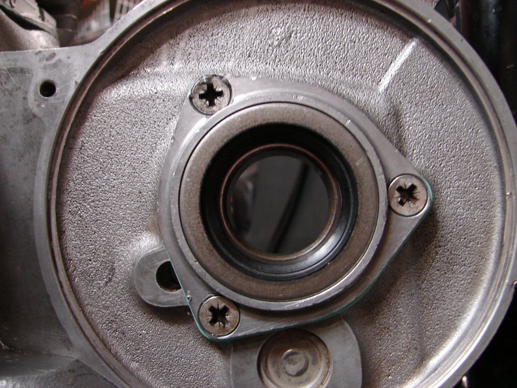
Unlike the old seal, the new one had plain steel outer surfaces and was significantly thinner, but it still felt as if it would be needing some serious convincing to go in. Fortunately I have a very serious drift which is just large enough to overlap the seal and raised surface around the seal cavity, so my only extra precaution would be to heat the alloy plate before attempting the fit, and the seal would go in the freezer for 15 minutes to get the max expansion/contraction scenario I could muster.
Boiling water straight from the kettle works brilliantly on alloy, and with that and the super heavy drift it went in perfectly right down until flush, without the slightest disturbance to either component. It feels smugly satisfying to turn a hazardous situation into a controlled one and get the perfect result.
The gear clusters now got the tenth degree inspection for any signs of excess wear that might indicate that trouble was on the way, but none was found. As can be seen, the teeth all have nice squared outer edges rather than the profile offered by the old oil pump gear which shows that life has been hard. The four speed Trident gearbox is not the knife through butter sweet changing device that the five speed is, but I get the feeling that it is a lot stronger. Having said that, when I stripped the gearbox from my T160 during a full rebuild at 41,000 miles everything was so good that I put the whole thing back exactly as it came apart, and it is still a delight to use 25,000 miles later. I figure this one will be too.
The idea is to mesh all the gears together and fit both mainshaft and layshaft at the same time, while trying to prevent the selectors from falling off and threading the shafts into their respective bearings on the far side of the case.
It is a three handed job and there is only room for one hand inside the case...
It took several attempts to get all the gubbings happily inside the case, as the selector forks kept disengaging from the camplate, until I had the idea of inserting a punch from the drive side to support the innermost selector, after which it all behaved.
I then trial fitted the outer case to make sure it would fit up happily. It did, but as I removed it the selector rod came out with it so I had to start again. Third time it was a well learned process and we ended up with all where it should be.
The sprocket was then fitted to the output end in order to hold the mainshaft in place, though the new lock washer needed a fine file around its inner edges before it would take up its rightful place. Another unfortunate comment on the fact that many new parts are not quite accurately manufactured.
The tightening of the various nuts on the ends of the shafts can be done by either waiting until both ends can be done together, or by fitting the rear chain and using the rear brake. The latter would require refitting engine mount plate and brake lever plus the new chain which requires shortening, so I figure it will be a "both ends" scenario.
I had noted that there was no gasket on the inner gearbox case when it came apart, and checking the gasket set there was only the outer one present. I figure I am the first person to be inside this gearbox since the factory, so I took a look in the workshop manual and sure enough, only sealant is used on the early 4 speeders, unlike the 5 speeders that I am more familiar with which have gaskets in both places.
As expected, there was plenty evidence of a grey sealant all around the inner case which put up quite a fight before leaving. All the bolt holes were equally infected, so this ended up getting as much attention as the crankcases usually do to make sure that nothing interferes with the ability to make it oiltight. Nice to see it looking like this before it goes together though. Shame nobody but me will get to see it...
The outer side has benefitted from the same level of attention, and all the threaded holes have had a tap run down them, while drill bits were used to get the majority of the old sealant out of the holes for longer bolts and studs.
I am not sure what the original sealant actually was in 1968. It seems far more serious than the silicones we now use, and while they do the job adequately, there are times when I could use some of that old stuff. Fortunately the surfaces of these cases have not seen any action until now, so there are no major surface scars which could torpedo our aim for a leak-free Trident. They have copped enough flak over the years for this very thing, so I make it a major consideration to do everything possible to prove it can be done.
After another careful test fit which went smoothly I treated the inner edges of the case with silicone sealant and pushed it home while holding the gear quadrant in the centre position as advised by the manual. Because the gearbox internals begin with the camplate in exactly mid position the quadrant gets timed similarly, and with only 3 dogs present for the gearlever to engage with it is the simplest ever to know you have it right.
The nut on the kickstart ratchet requires a torque of 42ft.lb so it has to wait until something happens on the primary side that allows me to lock it. As this nut was only finger tight when I removed it I can see why they go to extreme figures for insurance against accidental loss. I may be able to use a large open end spanner on the rear sprocket nut to be sure nothing flies off while tightening, and as it will need to be in gear I will get to check the gear selection first.
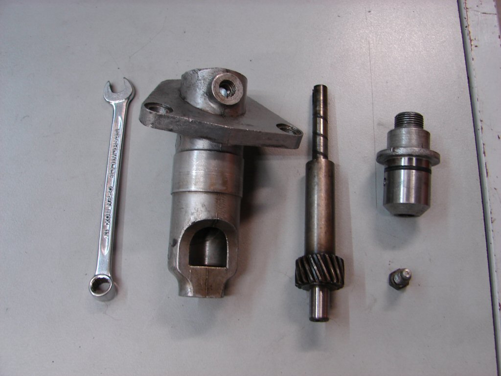
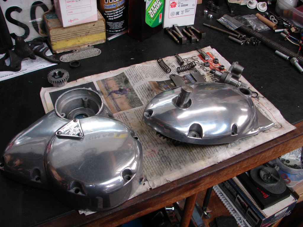
Preparation for the next step involves stripping the kickstart and gearlever shafts from the outer cover in order to replace their respective oil seals. Because this is the only time when the entire outer surface of the cover is going to be free of obstacles it is the ideal time to give it a polish. The timing cover got one too, as both covers are the last parts to get fitted after the critical nuts inside are fully tightened and locked.
The kickstart shaft has a proper oil seal which comes with the engine gasket set, so that was easily completed and refitted. The gearlever shaft uses an O ring, which can be seen just to the right of the open bush, and it was much the worse for wear. It is a very small cross section oil seal and was not included in the gasket set. Dang. Having not dealt with any other 4 speed boxes lately I do not have any, so immediately ordered a few so this does not catch me out next time.
As this means a slight delay I turned my attention to readying the rear wheel for its new chain, and the fitting of the oil lines. These are a bitch to fit due to the limited space where they join to the crankcase feed pipes. I had to shorten the new oil tank exit pipe as the larger hose now needed will not bend as tightly as its predecessor did.
While neither hose is under extreme pressure, they run at high temperatures, and I have found several in the past which had migrated along the pipe towards freedom, despite having the correct clamps in place. As a precaution I now place a cable tie around the outside edge of the two clips so that neither can move unless they both do. I figure that is highly unlikely and it is a very simple measure to fit anyway.
The major time factor in this operation is the fitting to the new feed line of the original protective spring which saves the line from harm as it is in the firing line from the front wheel, but as the new line is larger the spring really doesn't want to comply.
Mumble mumble...
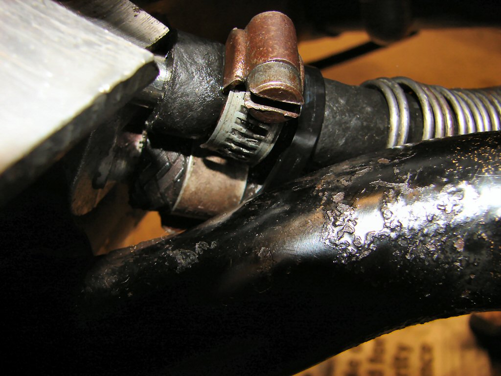
Sheer bloody mindedness wins. The original ubiquitous jubilee clips have been re-used even though I am of the opinion that they are seldom pleasing to use, but I admit that they usually do the job well enough.
As there is more room at the tank end, and as it is on full display, I reused one of the original clamps which are both nicer to work with and much more elegant. Despite the hose being larger it was possible to slightly reshape the clamp and it complied perfectly. I guess the names tell the tale - one is a "clip" while the other is a "clamp". Which sounds more serious.?
The ratchet nut and the front sprocket nut got tightened after finding that all gears did select properly, so the locking washers have now been applied on both sides. I also ran the new drive chain around its sprockets to see how much it needs to be shortened. Only one link will have to have to be removed in order that the wheel ends up as far forward as it will go, and thus give the longest life that decent oiling and adjustment can deliver.
The O ring for the gearlever shaft arrived but was a fail. It was simply too big in cross section to fit inside the bush, so it ended up looking like the old one. Funny that. So today I visited my O ring guys and bought a supply of O rings with a smaller cross section and had immediate success.
That meant I could reassemble the rest of the outer case and fit it to the gearbox. Using the gearlever I was pleased to find a very sweet changing box despite the lack of oil in it yet. I do lubricate such parts with a smear of engine oil when assembling, but the real deal synthetic oil will go in tomorrow.
The drive chain got shortened and fitted to the sprockets. That allowed the clutch housing to also be fitted, and the clutch hub is in place while I arrange a method of tightening the nut successfully.
While I cannot fit the engine mounting plate completely until the inner chaincase goes back, I will half mount it so the rear brake lever can be used. There is no lock washer arrangement for the hub, but the gearbox shaft is tapered and there is a keyway which securely locates the two, so there is no real reason why the nut would want to come off. I do however take the precaution of adding a smear of silicone sealant on the thread and also to the three screws which retain the housing. This is far less serious than using loctite which makes future dismantling a problem, but it discourages any of these well buried fasteners from even thinking about leaving.
So thats nice...
The engine mounting plate got fitted and will be able to remain in place from here on. The brake lever was fitted up and adjusted, and this allowed final tightening of the clutch hub nut. The clutch assembly now got a non-standard O ring fitted to the inner end of its spline, which prevents oil from the primary case from creeping along the splines and entering the clutch cavity.
With the entire clutch then fitted on to the hub, the inner primary chaincase can be fitted, but as it has not been touched since things came apart a considerable clean up was needed to remove old gasket, the remains of the defunct cush drive rubbers, and general old oil sludge. It has now been trial fitted prior to running a tap down all the threads, fitting a new oil seal for the cush drive and new O ring for the oil pump.
While cleaning the inner case I found something else which has been a problem until now. There is a small spindle which carries the oil pump intermediate gear and which has drillings to convey oil to the bush inside the gear. I figured that it should have its oilways cleaned, but the end hole was missing.
After a brief search the hole was found at the other end, which is in a blind cavity, whereas at the outer case end there is a small reservoir which collects oil thrown up by the chain and feeds it to the bush. This means that the gear has suffered from oil starvation since things were last reassembled, so I shall be checking that they are still a viable pair, though the shaft at least looks to have survived with a good surface.
I also realise that this could have been the cause of the excessive wear on the drive gear, as the oil pump gear runs in oil and will supply an amount to the intermediate gear by their relationship, but probably little of it would reach the drive gear. I would guess this mistake has been made in more bikes than just this one.
Although the spindle was reversed, the oil delivery hole had been correctly positioned at the top, as the intermediate gear is loaded at the bottom due to both of the other gears exerting an upwards force to this one, so oil can enter most easily from the top. All of these engineering principles can be deduced by careful inspection, as despite the sorry tales, the factory designers knew their stuff and everything is where and how it should be for good reason.
Finally, with all threads cleaned out and new seals in place the inner case was able to enter the fray with its freshly greased gasket already in place.
Now is the time when the final step in the enlarged oil feed has to be carried out, so the oil pump got stripped and cleaned. The back plate which contains the hole that has to grow bigger has a tendency to develop wear at the end of the two gears in the cavity behind it. There was very little evidence of this but as a matter of routine it gets a polish anyway. The freshly drilled hole is where the screw threads are pointing.
This was also the best time to have a good look at the gears. The first drive gear lower right is already replaced. The oil pump gear with the screw in retainer is definitely in good enough shape to carry on as is. The intermediate gear is the dubious one, and was displaying quite a lot of sharp edges where the teeth had been worn outwards, but it seemed to otherwise be a good risk, so I dressed both sides of the teeth and gave them all a good wire brush to dislodge any grunge.
The pump got reassembled and installed in the crankcase and the gears trial fitted. And then we found the answer. Having already come up with two possible explanations for the excess wear the real answer now looks very much to be version #3. Due to the oil starvation the intermediate gear bush has worn a great deal. You can see the obvious clearance between the bush and the spindle in the following photo.
This wear allows the intermediate gear to wobble side to side a considerable amount, and it seems most likely the odd wear on the edges of the teeth I had to file are evidence of this. With that in mind it is now possible to explain the state of the teeth on the drive gear, as it has been subjected to a lot of angular wear which is spread around a lot less teeth than the larger one, so is in far worse condition than that is. There are no gears of this type in NZ to be had, and it is quite possible that finding one around the planet is not guaranteed either. However, one local supplier has a new bush, which I promptly ordered, and which is of course a fraction of the cost of a complete gear.
As the spindle does not show any signs of excess wear I trust that this is the last hurdle and we have no more annoying discoveries...
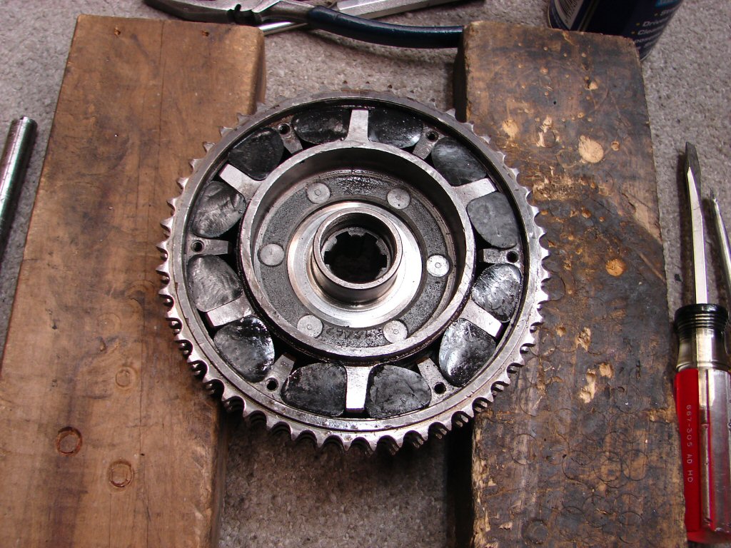
The next step in the primary dept would be the cush drive, which had already announced its need of new rubbers so there were no other surprises lurking there. It was exactly as it came out and appeared to have suffered some rust from a long period of storage at some time in its life. However, the locking tabs were looking quite recent, so it was possible that rubbers had been fitted at the same time as the new clutch plate and modified bearings went in. If so they had been bad rubbers, having failed so soon.
I chose to also remove the worn out bush from the intermediate gear while waiting for its replacement, as there was no other course of action that could be taken to arrange a suitable set of gears for the oil pump. Happily the bush came out in an agreeable fashion, suggesting the new one will go in the same way.
Sure enough, all the rubbers on the compression side of the equation had failed bigtime, and only powdered rubber was left of them, while the less stressed rebound rubbers had survived nearly intact. There have been periods of time over the last few decades when some very unsuitable rubbers have entered circulation, many of which did not last six months in service before turning into black goo. I once fitted a set of such to my T160 and when they failed catastrophically I thought I had run some bearings due to the deep knocking noises it made.
Apart from the mess and lengthy cleaning process though, the cure is straightforward and assured of total success.
Inspecting the remaining old rubbers I found them to be quite easily compressible in my fingers, which they should never be. The new items I have been using for some years now are, if anything, a total bitch to fit because they not only completely fill the available space but are virtually incompressible other than by using screwdriver blades and drifts in order to coax them into place. I also apply a coat of WD40 to help them slide against the coarse surfaces of their enclosure, but it is a real struggle to get them in as far as they can go.
I fit all six rebound rubbers first, then use vicegrips to force the spider to compress them as much as possible while inserting the compression set. Using two screwdrivers together seems to afford the best leverage around their edges, as any corner which has not entered its cavity will get sliced off if you give it half a chance.
Despite all the above, the best two tools are patience and uninterrupted time.
It is always a great relief to be happy enough with the fitment that the cover plate can be bolted down. I work my way around the tiny bolts bit by bit so it all gets compressed at an equal rate, then back it all off again to see what happens. If the plate wants to rise up again there is some trapped rubber which needs further attention. None did this day so I gratefully added the locking tabs and retightened the bolts to a firm but not overly tight tension. I have never snapped one and am aware that the major reason for them to stay in place is the locking tabs and not a herculean grip. The locking tabs get folded right over the bolt heads, as space is quite limited in this area and any contact is to be avoided.
I then removed the upside down oil seal from the cush drive retaining nut and drove a new one in correct side up. Seals always fit with the oil to the spring side of the seal, and the oil here is in the chaincase not the clutch.
Being at a point where the oil system is mostly complete I add some oil to the tank and crank the oil pump gear by hand to circulate oil through the engine. I begin with the oil filter removed in order to get a little oil to where I can see it well enough to purge any that looks manky, and as it was nice and clean I fitted the filter and continued to pump further. When pressure begins to build up it is clearly felt by resistance in turning the gear, shortly after which oil can be heard escaping from the crankshaft bearings. This means that lubrication will be almost instantaneous when the engine is first started.
With that all happy I trial fitted the primary chain and sprockets to make sure nothing was going to be a reluctant fit when final assembly came around. It all slid home as it should, but will have to come off again in order to refit the missing intermediate gear once the new bush arrives. I can however use the trial fit to fully tighten the rotor nut in the timing case and button that up, which will in turn allow me to fit the Trispark igntion and complete the wiring work associated with that. There are also the three alternator wires to repair and complete the charging circuit.
A steady reduction in the list of remaining jobs is now taking place.
Yay.!
Thanks to the efficiency of our NZ spares providers the bush arrived today, so that was first priority. It felt like a firmer fit than the old one so I heated the gear in boiling water first, then drove the bush in using a nylon drift which succeeded admirably. Even better the gear is now a perfect fit on its spindle with no side play at all, and I am happy with the mesh quality of all the teeth.
The complete gear set was now installed with oil where necessary and the special screw which retains the oil pump gear got fitted with a smear of loctite to curb any ideas of ever loosening in action.
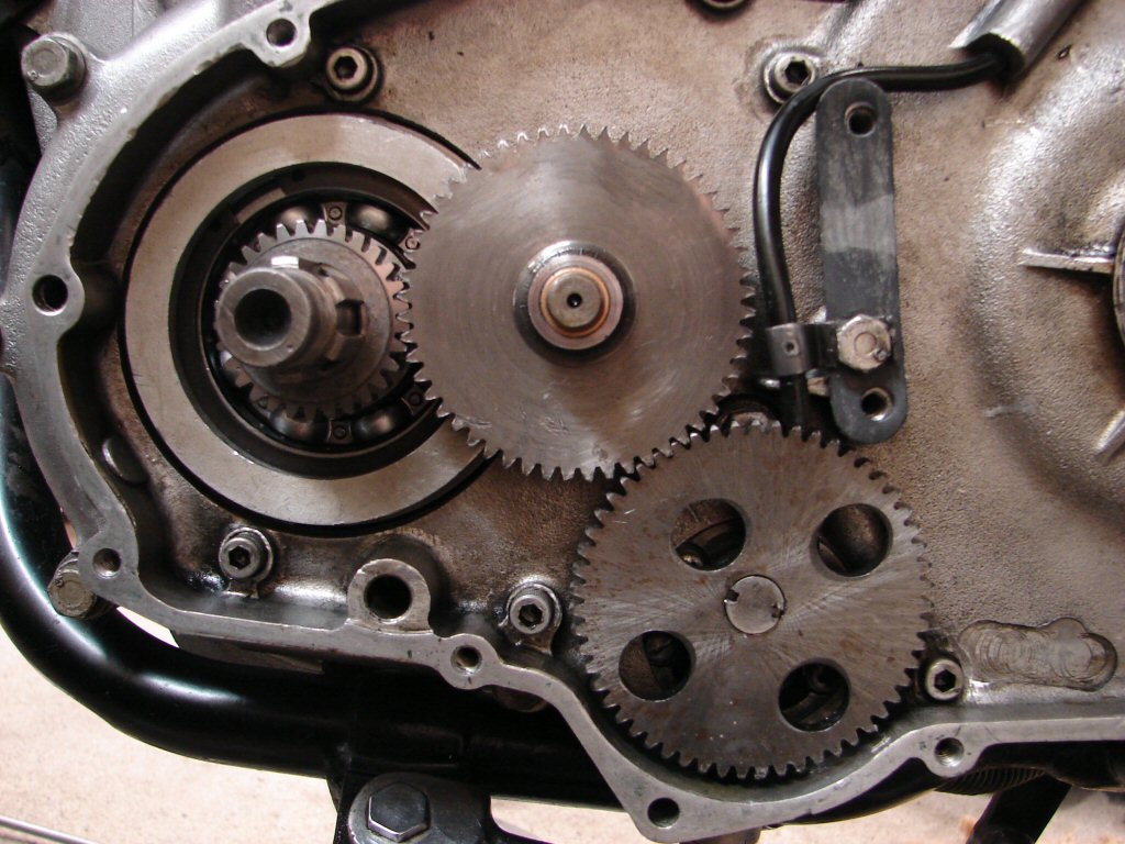
As the rotor nut was now tightened I locked its tab and fitted the timing cover over a greased gasket. I was pleased to note that the original philips head screws were in use, so I treated them to some stainless wool to brighten them up a bit. Allen screws are transformative things, which enable the less sensitive to rip the entire alloy threads out of thin alloy cases such as these, so I am appreciative that nobody had fitted them here in the past, and thus view the original screws as worth celebrating to best effect.
The engine was now positioned to No.1 cylinder firing position, as evidenced by the mark on the rotor aligning with the end of the pointer screw, and the Trispark rotor fitted to where the installation instructions reccomend it to be. I often find this position to be a little retarded from the optimum, but as I check with a strobe light on first or second start and correct if necessary it does not matter greatly.
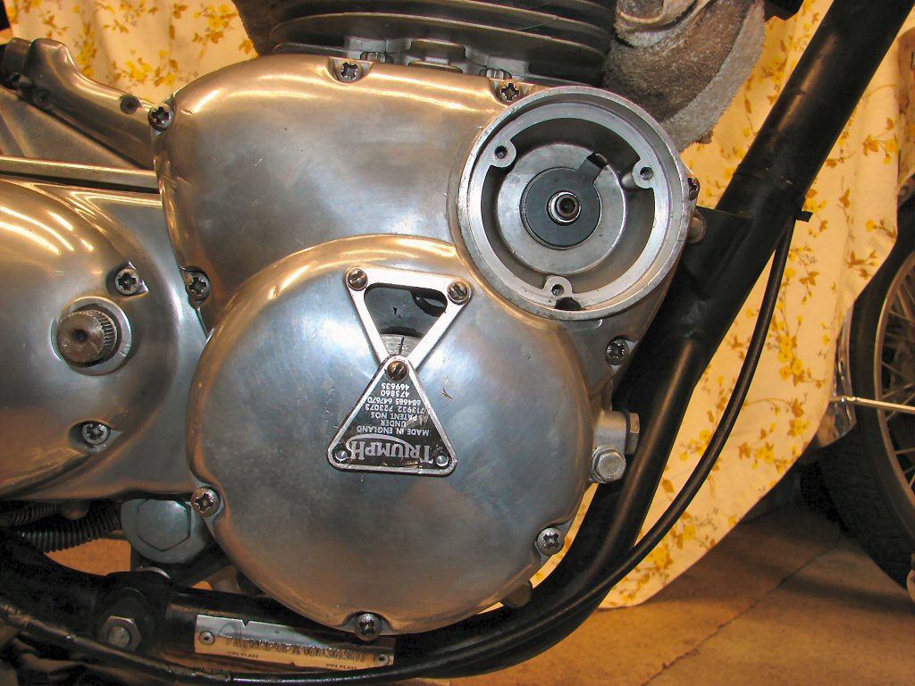
I figured I would fit the pegs and levers at this stage, as it will ne necessary to use the kickstart to turn the engine in future, and the footpeg would no longer be a nuisance as most work on this side is now complete. The footpeg then presented a problem which I could see was both preventing it mounting properly or for the retaining nut to tighten properly.
It only takes presence of mind and common sense to resolve these matters, but those in a hurry will rush on and reinstall the same problems over and over until something is destroyed. The very thick flat washer had been colliding with the two locating pins, which gives the initial impression that the pins are too long. Looking at it I decided that the very thick washer was not installed by the factory, and probably there should be a spring washer instead. The parts manual confirmed this, on the right peg only, but of course a new style spring washer is of too greater cross section. So I looked in the place such older things live and found the very washer we needed. It then got a wire brush and some grease and everything went together as it rightly should.
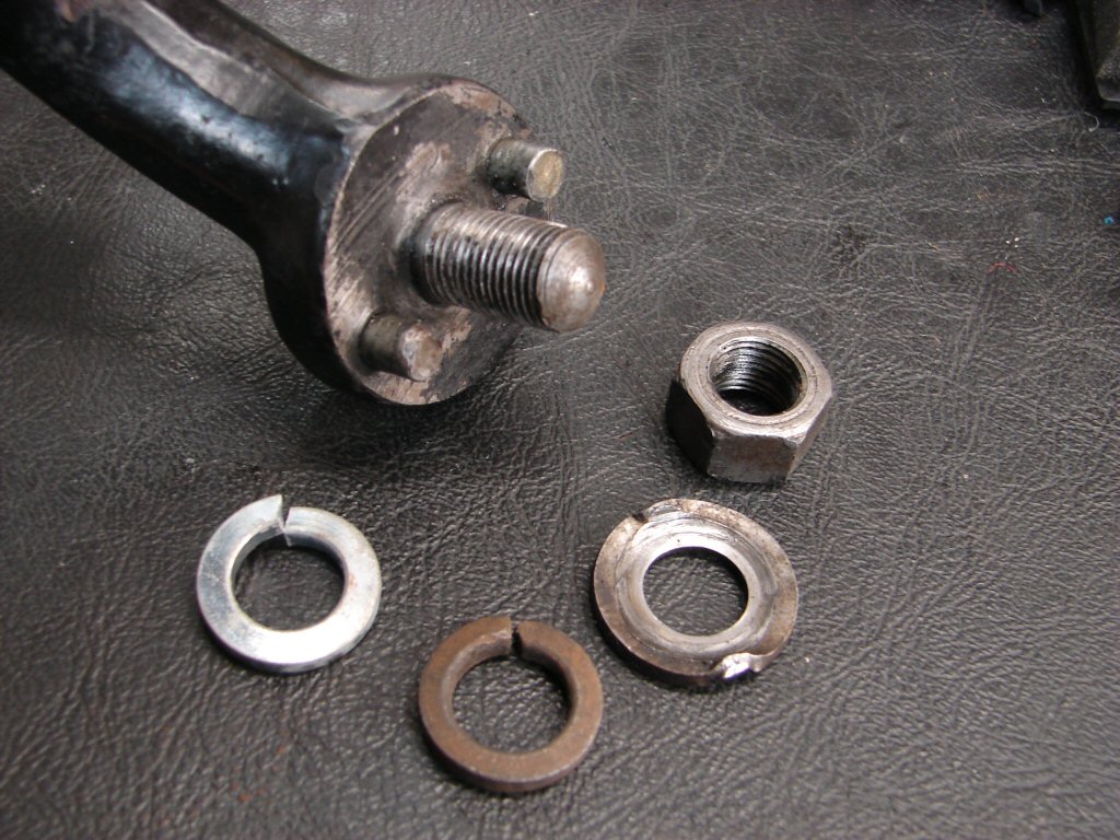
The kickstart cotter pin needed its thread repaired, a bit of filing, and the threaded part was bent and took a little straightening. I now inserted the pin from the rear. which rocks the lever slightly further forward than the other way around, as it acts like a wedge. This has rectified the rearward rest position the bike arrived with, but more importantly, it restores a missing part of the lever's arc of operation, so kickstarting will now be easier.
I then put the seat on the bike and used my size 10 boot to show me where the gearlever needed to be set in order that an equal amount of ankle is needed for up and down gearshifts. While I am accused of being a perfectionist I merely set these things up so that when I eventually test ride the bike, everything should work as intended.
Someone might bring me a bike with an oil leak to fix, so I do that and then I do this before testing it. When they come to ride their bike home I tell them to let me know what the bike went like. They often tell me - wow, it goes so much better, did you tune it.? I tell them that I don't think it is going any better at all - it is just easier to ride.!
It is all just common sense taken to a logical conclusion.
While I resist the term perfectionist, I am disappointed that any gasket company making gaskets for old British motorcycles would ever use bright green gasket material. Well, they don't on my watch, as I run a black marker pen around the glaringly obvious ones like the points cover. Take that.!
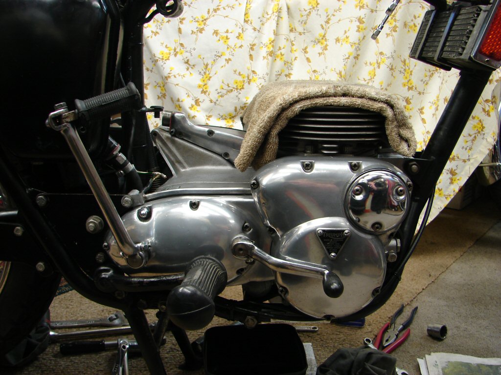
The primary chain was now finalised, with the tab washer locked on the sprocket and some loctite applied to the threads of the cush drive retaining nut. I fold a piece of insulation tape over the pullrod threads to avoid any chance of scarring the new oil seal as it slides on, then I have a deep socket to allow tightening of the nut "significantly" by using the rear brake to control things. I have seen many of these nuts come loose in service, so the threads have to be completely oil free and an amount of loctite that covers about 4 turns of the thread but not thickly. Results have been excellent using this method to date.
I then checked the pullrod thread by running a nut along its length, to find that there were tight spots, so I ran a die nut up it and eased it smooth. The small screwdriver slot at the end does not respond well to severe use, so if you can't run a nut up the thread easily it is going to be a bitch to adjust the clutch. It can also be a bitch despite this...
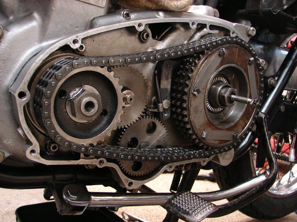
The outer primary cover now received its massive cleanup, and there were ample remains of the rubber/oil slurry left behind by the dissolved cush drive. Cleaning the output needle roller bearing revealed that the thrust washer which covers it was freely spinning in the alloy recess where it lives. I applied a number of peens with a cold chisel and it is now secure as it should be. This thrust face mates to a radial needle roller bearing as seen in the above photo, and it is imperative that the bearing operates as a roller rather than sitting against a sliding face which will wear the tiny rollers of the bearing while preventing it from working as intended.
There was another flaw uncovered here. There are two hollow steel dowels, one at each end of the primary inner case, which locate the outer to inner joint, while allowing fixing screws to pass through them. I had noticed that they were absent from the inner case, and sure enough they were in this outer, but they were so far into the screw holes that they were flush with the joint surface and thus doing nothing at all. I am without any idea as to how or why that had taken place. I had to heat the alloy case and partially drill the dowels to get them to finally spin in the recess before I was able to extract them. Fortunately they survived the ordeal and are now pressed home to half depth in the inner case and a trial fit of the outer case showed it to be mating perfectly.
I would have to state that I seldom if ever encounter as many incidental problems as the last two bikes have presented. It seems pretty certain that most of them have been related to incorrect assembly at some earlier stage in their history, but the good news is that of course every involved part is now going to function much better than it was prior to now.
The larger boss to the right centre of the case is the one which collects oil and feeds it to the intermediate gear spindle. Good to go.
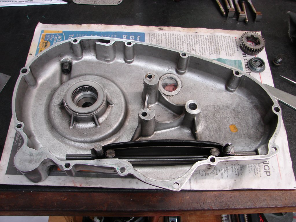
I was checking the viability of the clutch cable as it will soon join the mix, and I remembered that it had not been adjusted correctly when I dismantled it. A lot of these cables are for some reason manufactured with their inner cable being too long, so there is not enough adjustment thread available at the primary case and the handlebar lever to get it right. I now see that the adjuster at this end is missing its locknut, so it only has one position, which is fully down. This is even more extreme than it would be with the correctly fitted adjuster as there would be a washer and a locknut between the adjuster and the case. I stock some modified adjusters that are made by L P Williams in the UK, and they have an extended tube within the case which discourages oil from coming out of the adjuster/cable joint, which was a perennial problem. If this one gives me any trouble I shall fit the modified type.
I found a nut and appropriate sealing washer so the original adjuster got spruced up and it looks to be about right. The cover went on its greased gasket happily and I tightened all the screws after making sure they were in their proper places. I decided to fit the clutch adjustment cover so that I could polish the whole thing, but then found the cover holes were full of old sealant so I had to run a tap into them a few times. I fail to see why there would be sealant in blind holes, as nothing can leak out, but maybe I am different...
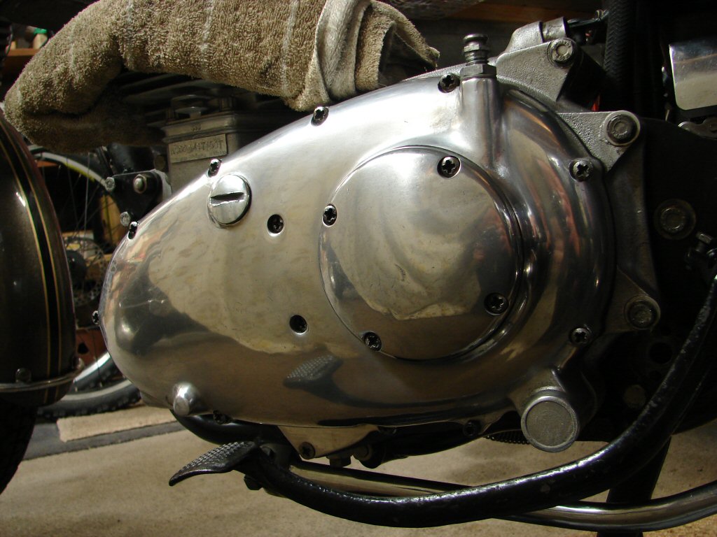
Next job is to do the electrical repairs before the head goes back on and things get a bit tight for manoeuvring space. Because the alternator connections are right where the Trispark wiring loom arrives it makes sense to tackle these two jobs simultaneously. I favour the original Lucas bullets as opposed to modern brass ones, as the old type are re-usable and are a better fit inside the female connectors.
While all the prep takes more time than a commercial enterprise would be bothered spending, commercial enterprises also get a lot more of their work returned because some part of the repair was unsuccessful, so they have to visit it a second time. By taking the best approach and using the most suitable parts - especially electrical - things work the way they were intended and just keep doing that. This is why you see three old Lucas bullets about to serve their second tour of duty, so they may make the century.
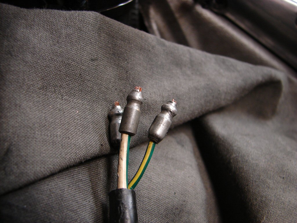
The soldering went well as these old bullets are of a material which behaves wonderfully when solder is applied. The solder flows easily into the wire then the excess disappears inside the bullet as the temperature equalises, leaving a very tidy finish and no buildup on the outside edges such as brass ones tend to do.
The connections can be quite difficult to press home which is how you would want it, if it is going to remain a proper electrical connection for many decades. I have an old pair of slipjaw pliers which manage to grip the back edge of the bullets and squeeze them in from both ends simultaneously. It is necessary to compress the outer plastic covering to ensure they are fully home, as the metal female connector is shorter than the plastic.
A tidy job is pleasing and worth the effort.
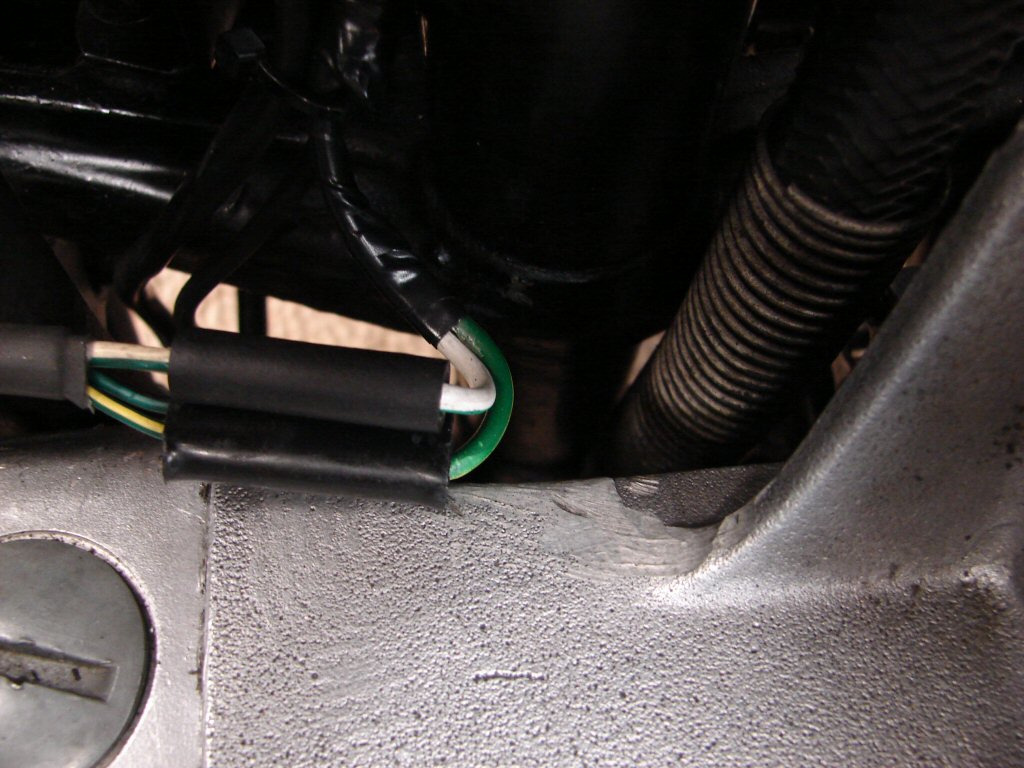
I was then able to secure the wiring harness and Trispark loom up the frame and around to its destination at the black box. The connections were restored to their places inside the box then a few earths were added, including placing an earth stud on the tray so the two horns have earth connections next to the relay which will power them.
As the Trispark fuse was using a red wire I used it as a fused earth. The ignition system has a 17 amp fuse which is too highly rated to protect the electronics, so the earth fuse will take care of that task should it ever be needed. I have found on a lot of old bikes that there is a fair amount of voltage loss between the battery and an electronic ignition, which is highly counter productive. While the wiring harness here is new, the switches are all old, and they can be the cause of such problems. If I find that the Trispark is not getting the full benefit of what the battery has to offer I will fit a relay to bypass that problem, rather than attempt to overhaul the old switches.
Otherwise the electrics are now fully completed.
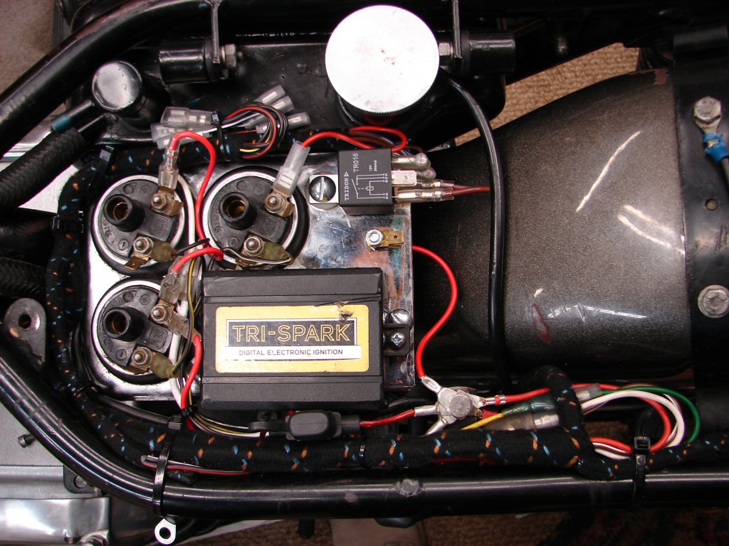
The clutch cable now got trial fitted in order to find out if it could be adjusted properly. The answer was a resounding 'no'. The inner cable is more than an inch too long which means that even using the full extent of both cable adjusters it is not possible to operate the clutch successfully. This is entirely due to incorrect manufacture of the cable, which would have been a premium model when supplied.
I have had to deal with these cables on numerous occasions and have a set routine. The cables feature an extra fitting which was never standard, and seems to be intended to deal with the abutment oil leak where the cable enters the primary case. My solution is to cut one end off the cable, remove the extra fitting, then shorten the inner by usually 1½ inches to get things just right. I measure each one in place first, as some differ in dimensions, but this one definitely needs the 1½ treatment and a new nipple back on the cut end.
The centre bit is the problem child, and its additional length has resulted in the inners being too long regardless.
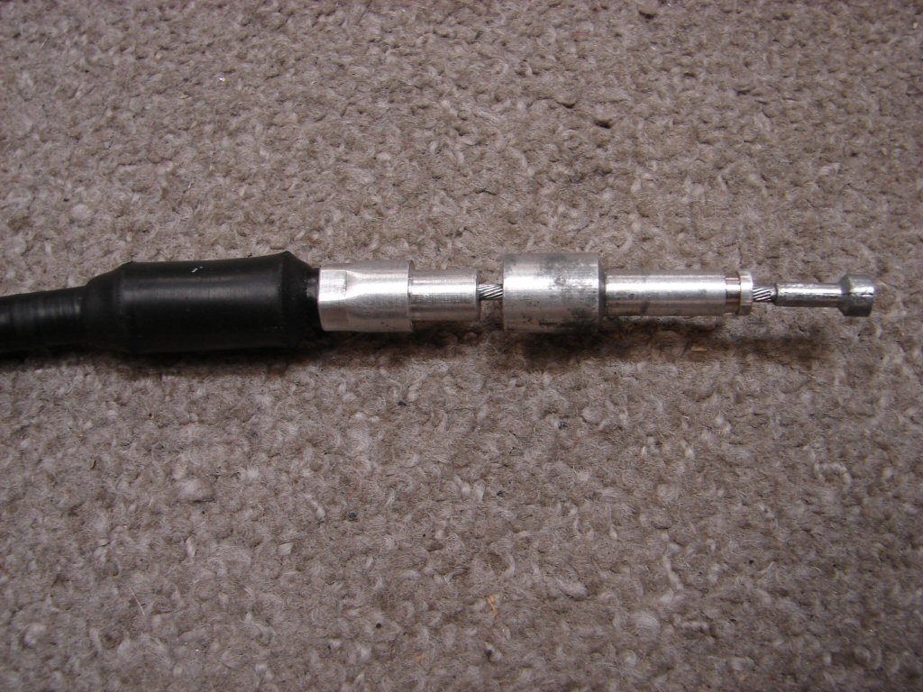
Next job was to sandpaper all the pillar and head studs, many of which had a thick coating of baked oil from the old leaking head gasket, which made getting the head off a major battle. I also run a tap down the inside of all the pillar studs, as the oil goes in there too, and at least one had wound out with the head bolt.
Once done I trial fitted the new head gasket, which as per usual was really tight on the studs. I presume these gaskets are stamped, and the burrs left on all the holes make them too tight to settle down nicely on the block. I use hand held drill bits to ream all the stud holes as well as the small holes for the oil drain dowels. One of those holes was noticeably offset which would cause major issues when the head goes on unless dealt with beforehand.
These days 'quality control' is our responsibility if we want things to go together properly and avoid distorting a new copper gasket.
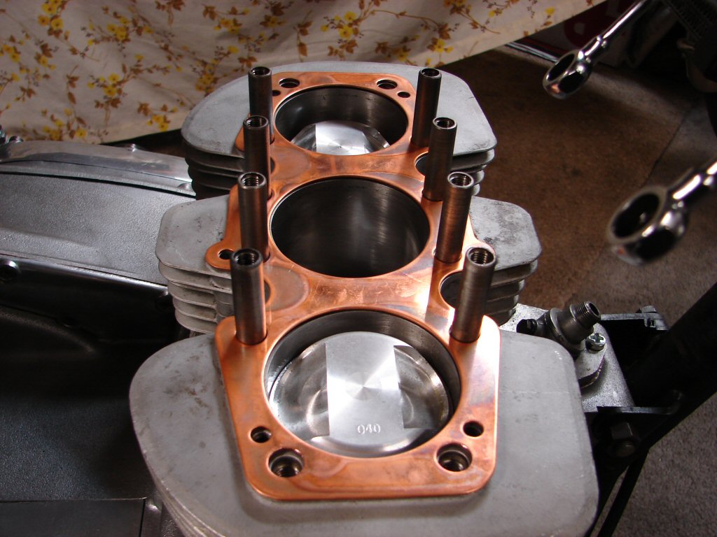
Knowing what a bitch it had been to get the head off I wanted to test fit the head in case some of the holes for the piller studs happened to be undersize and needed relieving a smidge. I was most gratified when it slid neatly over all the studs and assumed its rightful place with nary a scrape. Spiffing.
I had also performed a minor operation on the crankcase breather hose which had needed to approach the oil tank fitting from a slightly different angle due to the new wiring loom now being where it should be. A bit of hot water treatement was applied to both ends and it is now secure and holding its new shape, so another small item off the list. Can be seen in place here.
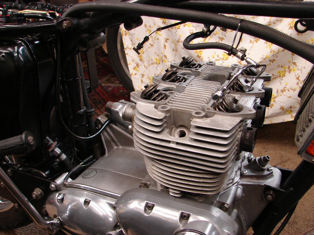
A brief delay ensued while the clutch cable got shortened and I waited for the rain to stop so that I could use my copper gasket spray outside to coat the head gasket. Today under a pale sun I managed to do that, so the head got partially installed in the same time I would normally get one completely installed. The problems continue to surface, with a bent head bolt and a pushrod whose end cap had obviously been running loose enough that it fell right off as I was cleaning it. It is also sensible to fit the exhaust manifold as the head goes in place, as on some bikes, depending on how the oil cooler is mounted, it simply will not go in there once the head has.
The bolt got straightened and the pushrod repaired, so with a light smear of silicone sealant the original aluminium rocker box gasket was put back into service, and the fiddly job of locating all the pushrods in their respective rocker arms while gradually pulling the head bolts and allen screws down evenly was completed. I had checked the amount of pushrod tube seal compression we were going to achieve, and thanks to the extra thickness of the copper head gasket there was not enough, so an additional gasket was fitted underneath the lower seal cup on all four tubes. I always do the exhaust rocker box first because the pushrods fall forward and are difficult to coax back if the inlet rocker box is already in place.
That got us to here.
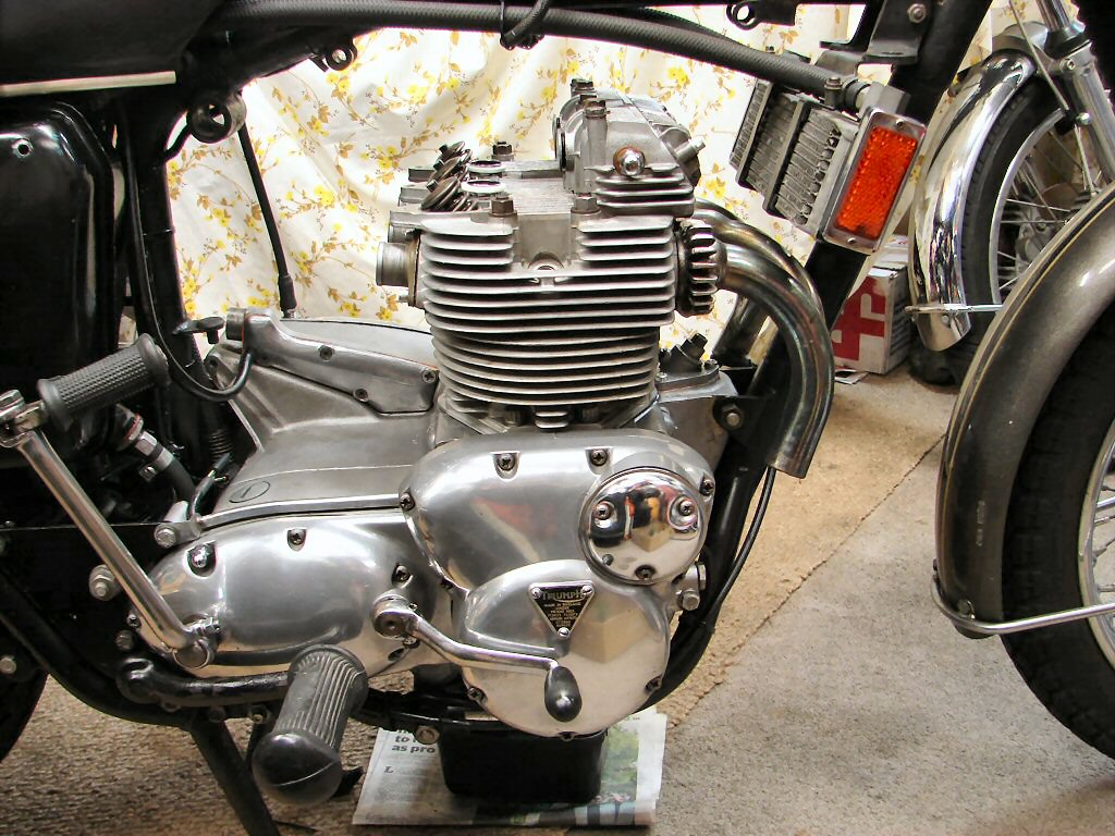
On the other side the clutch cable fitted after drilling out the abutment to accept the slightly larger diameter ferrule that the cable presents once the useless extension has been removed. It all adjusted up successfully and we have a working clutch, although I had to repair the handle bar lever which would not tighten on the bars properly now that it had work to do, so I fitted a shim to make it behave.
Being on that side I also adjusted the primary chain tensioner and refitted the rear brake light switch, which works happily on a multimeter so should do the same in service, all things being equal.
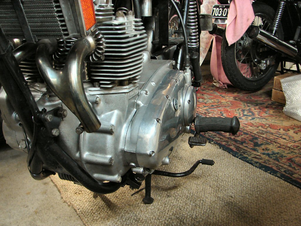
Once the inlet rocker box was fitted the cylinder head got torqued, which then allows the valve clearances to be set. I started with the exhaust side and quickly found that only two valves were moving. When fitting the rocker box one of the pushrod tubes had failed to locate properly in the base of it, so I loosened the bolts off and raised it enough to coax it in. Unfortunately the assembly lube had gripped very well and it had lifted the centre pushrod out of the cam follower. So the rocker box came off and I started again, with new sealant on the base gasket and a bit of oil to keep things happy until the oil supply arrived on first run. This time it all behaved and the valves adjusted without complaint.
I left the inlet rocker box cover off so I could view the inlet valve behaviour on No.1 cylinder and fine tune the ignition timing by using the LED on the black box. I had fitted the spark plug leads and a set of plugs, and made sure we had three timed sparks happening. When the bike arrived it had resistor type spark plugs fitted, such as are required by the Trispark, but when assembling the plug leads I found that it also has plug cap suppressors fitted. One of these suppression systems are surplus to requirements and may reduce spark energy, so I will fit non-resistor plugs of the Champion N3 flavour. Just what the factory ordered.
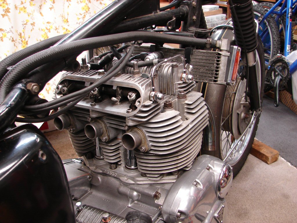
I treated both rocker box inspection gaskets to a uniform smear of grease, which improves their oil tightness, then buttoned them up. The carbs and airfilter then went on, although the filter will come off again for tuning purposes once the engine has been run, cooled, then a head retighten and valve adjustment if required. The first run is really to check oil pressure, basic tune of carbs, and strobe ignition timing.
The second run will involve a test ride then a more comprehensive carb tune involving a vacuum gauge to balance all three accurately. I find with the T150 and Rocket 3 exhaust manifold the centre carb is always working harder than the outers even when all slides were set the same on the bench. I attribute this to the fact that the outer headers act as extractors and scavenge the centre cylinder more effectively. I doubt that it matters over about 1/8 throttle, but we want the bike to idle happily so it is worth the effort.
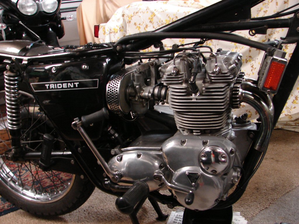
There were now a number of small items to complete, the bar end bobbins were fitted, and thanks to the fact that the new bars are slightly smaller internally there was a degree of both internal and external filing needed. The primary drain plug/chain adjuster access bung was cleaned and fitted with a smear of silicone, as we are close to filling all the oils.
With the battery fitted all the electrics were checked and everything works as expected. I shall fashion a battery strap to restrain the Motobatt from any weird antics and am working on the horns, one of which was missing an internal bracket to hold the domed cover on. They will also get new wiring up to the horn relay. New spark plugs also fitted and working.
When you are tending to the little bits that get left until last you know the finish line is in sight.
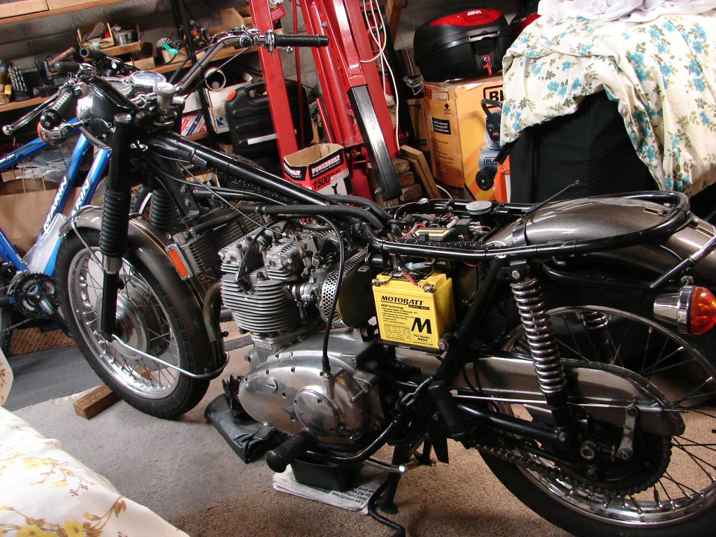
Primary drive and gearbox received their required oil quota, and a light smear of silicone on the new O ring seals as the inspection caps are prone to mild seepage otherwise. The gearbox oil is a fully synthetic 75W-90 which makes a noticeable improvement in the ease of gear selection while maintaning the recommended viscosity rating for gear teeth preservation.
The seat and sidecover were trial fitted as there are a lot of potential clearance issues around the sidecover retaining knob, what with all the wiring and repositioned oil line. Fortunately it fits with a bit of gentle persuasion, although it is vital to avoid lifting the seat too high while the sidecover is in place on these bikes, because the seat interacts with the sidecover in a harmful way, thus the knob has to be fitted and removed more by braille than sight.
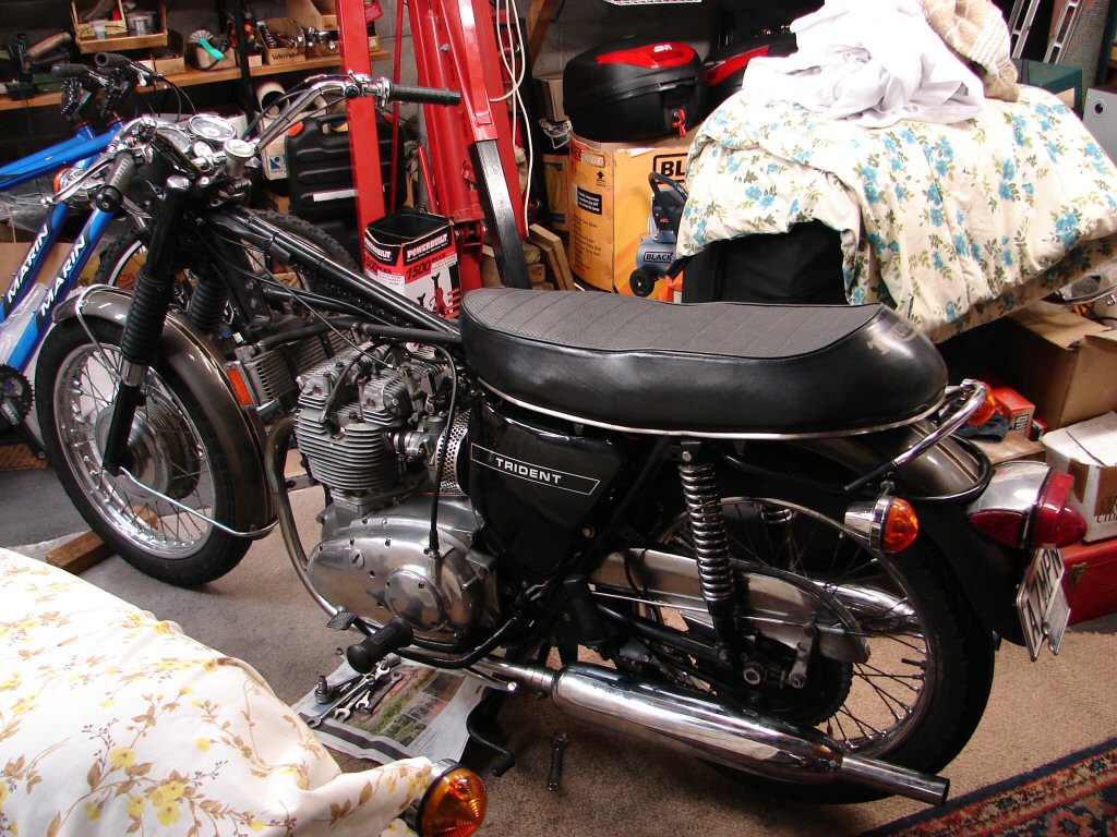
The header pipes got a mild polish before going back on, as it is difficult to reach the chrome surface once they are in place. The mufflers are still accessible when mounted, so they can wait until the final positioning is complete. The mufflers appear to have been at different lengths and heights and have some odd mounting brackets, so a degree of swapping will be tried to get them as even as possible.
There is also a clearance issue with the right side muffler-to-pipe, as in, there is too much. I will add brass shim if I am unable to reposition the adaptor well enough to do its job properly.
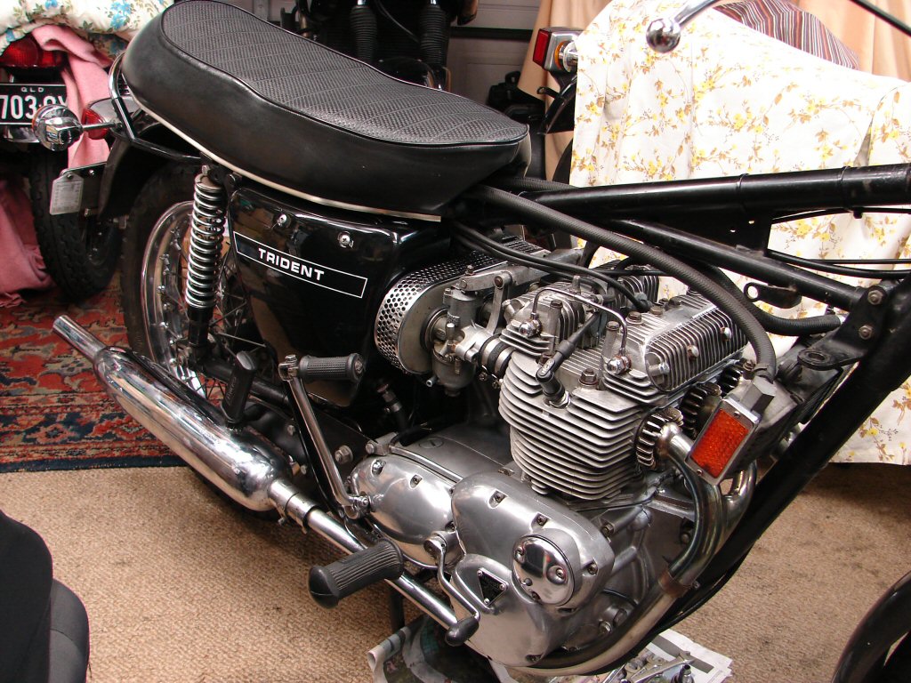
As time was pressing I made do with smaller items today. The battery strap got made up and fitted well, with room for adjustment should a replacement battery come along at some stage which is a different size.
I also made up the remaining fuel lines with appropriate clamps which some wof establishments require in place these days of ever increasing regulatory madness. I will admit that the original fuel lines were reaching their best-by date, hence the intermediate bits had been replaced while the carbs were apart, so these are the finishing touches to the fuel dept.
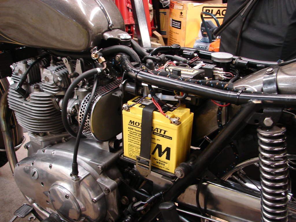
The seat has only one of its four rubber buffers fitted, and the lack of holes in the covering material would suggest that it has not had the others since this cover was fitted. The lack of these rubbers makes the seat a bit unstable in use, but more to the point it has all the rider/passenger loading now being taken by the hinges, and they are apt to complain by bending out of shape.
While such things are seldom seen, they are not right unless they are, and with the amount of work undertaken thus far it would seem foolish not to get all facets of the machine up to the same standard, which should also future-proof it for long and reliable service.
And that is the plan after all.
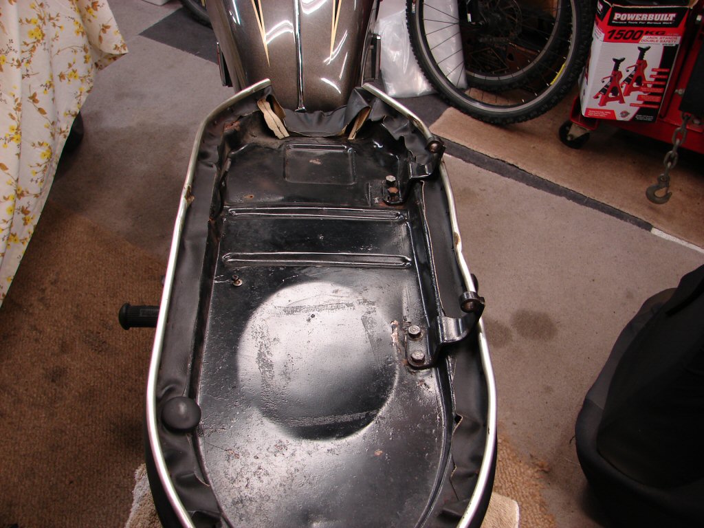
The new fuel tank rubbers were problematic so I repaired the one correct original and made another from a larger rear tank mount, so the tank mountings are now complete, although they will be disturbed a few times during the rest of the process of head tightening after the engine has been heat cycled a few times.
The head steady arrangement is left off until all of the work is complete, and can be left off completely from all accounts, as those who have raced these bikes report very little observable difference between fitted or not. This is reinforced by the fact that they were never fitted to T160's even though the lower mounts are identical.
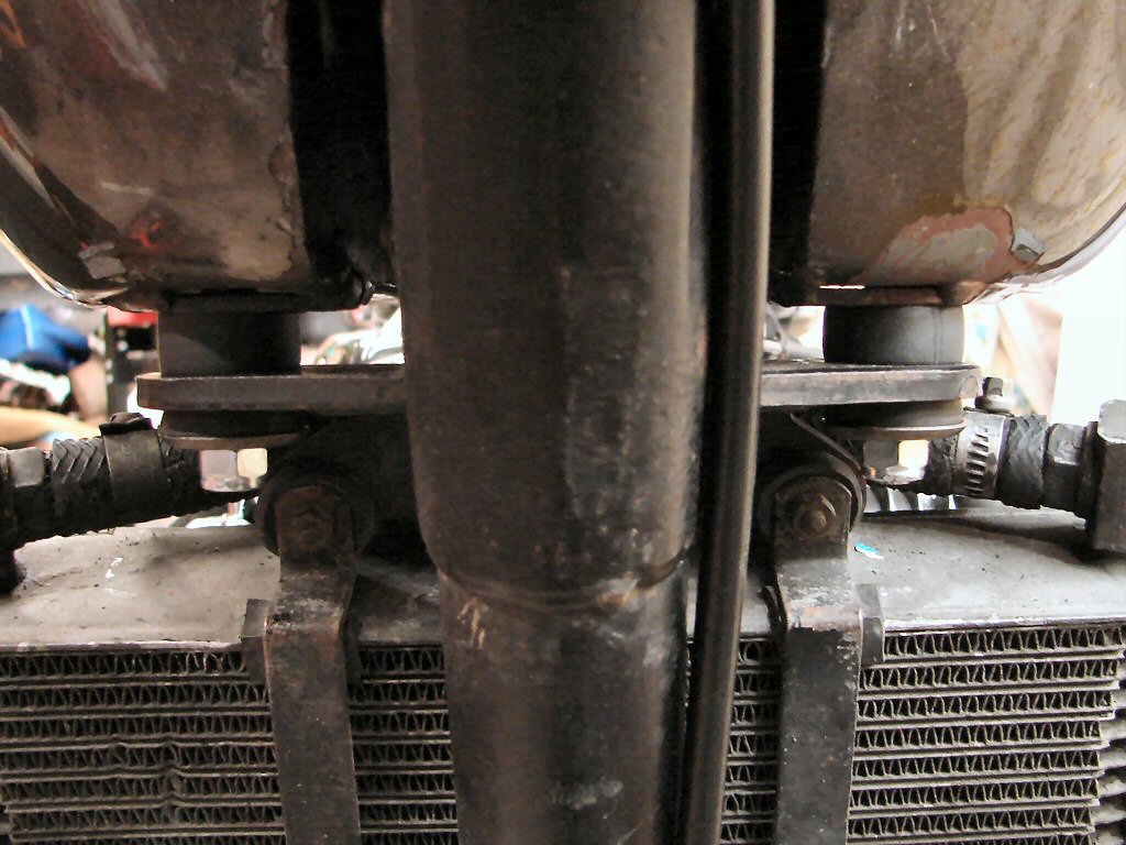
The seat got its threads cleaned up and a rusty bolt replaced during the fitting of the missing buffers. The new rubbers come with a flat cut on one side, as they usually end up hard against the outer lip of the base. On this seat there is room enough for round ones to be used at the rear at least, so it seems that the seat base may have changed sometime early in T150 production.
Very pleasing that the seat cover and edge trim are in excellent condition, as both are a fiddle to fit and many replacements are not true to the original parts. It has been a great relief with every discovery of bits in reusable condition considering how many were not. You simply don't know until it all comes apart...
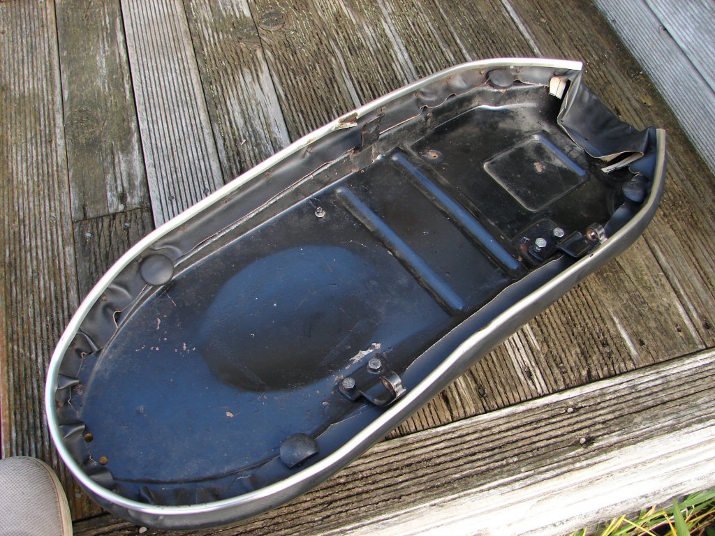
Spoiler alert.!
I just can't help myself at times such as this, and had to trial fit the seat now the tank was bolted down in its final position. I know that it will come off again for the final stretch, but it only takes a minute to sit it on there and take a photo of a virtually finished bike.
I'm thinking that it is going to be worth all the effort when all is cut and dried.
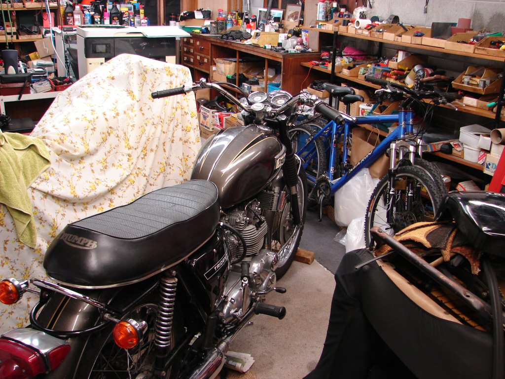
I had been putting off tackling the horns until it was inevitable. Such jobs are enormously time consuming compared to how much can be done in other departments. There was one horn fitted when the bike arrived, but it can't have been working as the horn relay was welded in the 'on' position so it would have been going all the time. This horn was the left side job, and as fitted it has potential to interact with the rear brake rod. I am not sure how it can be mounted to avoid this, but either from that or some other incident the two alloy halves had split apart, so some remedial work was carried out with partial results, as the small alloy rivet was hard pressed to restrain things from spreading again.
Both horns needed rewiring, during which I discovered that the right side horn had been reassembled 180 degrees out. Because the wire terminals have screw heads on the outside but nuts on the inside the whole thing had to be taken apart to replace the wiring connections, so I reversed the screws and put the nuts on the outside to cure that obstacle for the next time they come apart. They both have their new wiring and sleeving in place and the last job will be to fabricate the missing bracket for the right horn whose job it is to retain the domed cover. I also had to drill out one of the small bolt holes to allow the wires to exit as per the left horn, but mirrored as it will be mounted in reverse on t'other side.
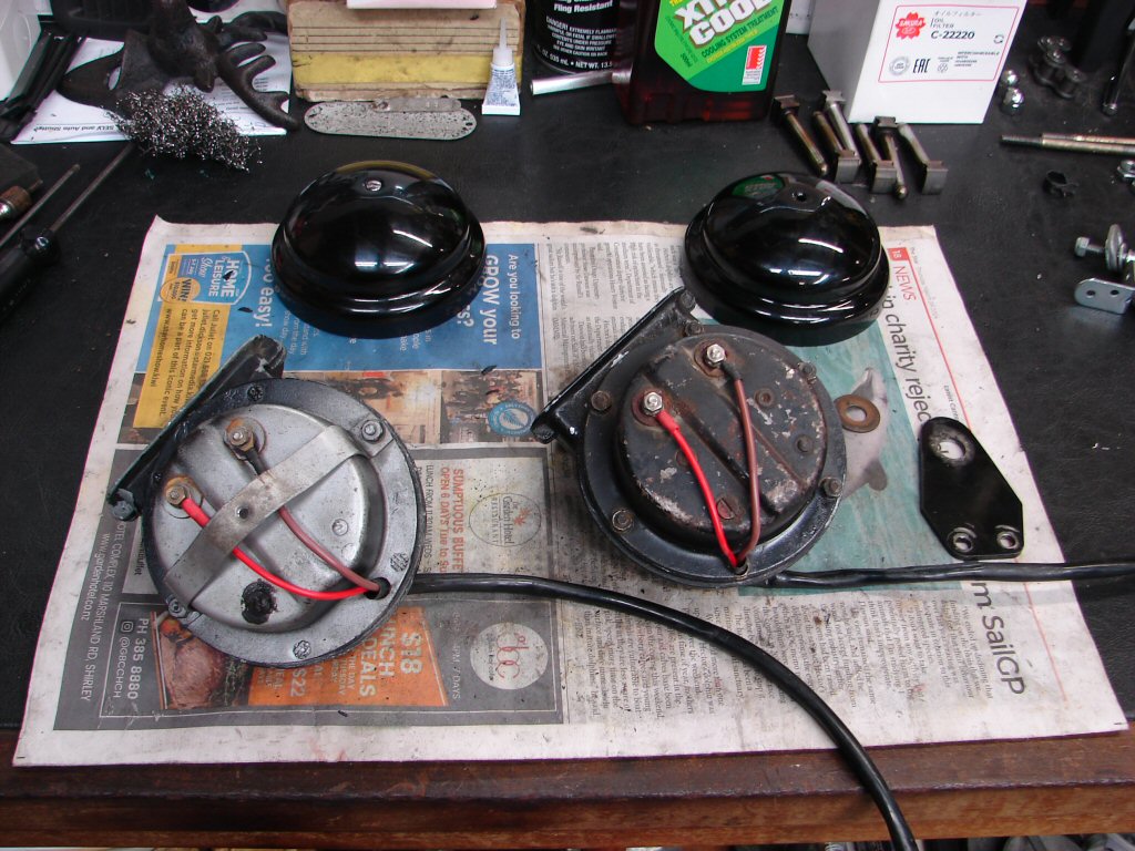
After a bit of straightening of bracketry I tried mounting the left side horn, but it was still on a collision course with the brake rod, so I used longer bolts and fitted a nut between the horn bracket and the frame lug. This has both provided a spacer and will act as a locking nut to prevent things coming loose, which these brackets usually do. There is now enough clearance that the brake rod will mind its own business.
The wiring was completed and the horn operates as it should, although perhaps not as loudly as it might once have. They are adjustable but it is a risky business due to the age of the 'points' type contacts inside which often refuse to play ball when disturbed. As I have spent more than enough time on the horns it will at least fulfill the needs of being a working horn for a wof.
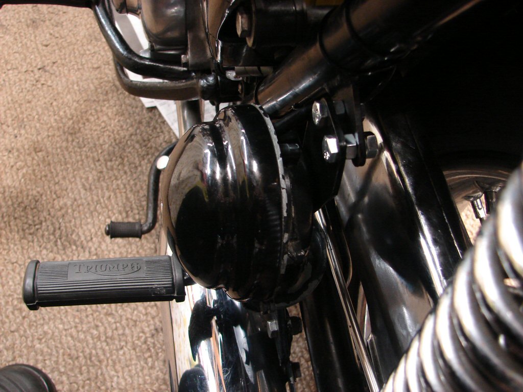
The right side horn is also now complete, but the frame lug is irrepairably broken. It can be forgiven in this case, as it had been converted to swiss cheese at some stage past, and did exactly what you would think it might.
I have however seen many of these lugs which have broken, presumably due to the sheer weight of the monster horns used at the time. The frame lugs are only 1/8" thick so a bit underengineered considering. I have thus made a template and will see if I can get half a dozen made of 3/16" plate for this and future repairs. The original will need to be ground completely off and the new one welded in place, after which the holes will be drilled to suit whatever horn bracket is present. The paint will also need to be repaired which may mean waiting for a much warmer and drier atmosphere than we are currently not enjoying.
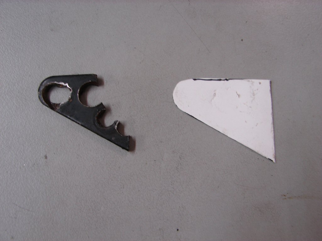
Along with these fiddly bits the tacho cable got fitted, seat and sidecover fitted, after moving the seat check wire away from the mudguard bolt and back to the oil tank mounting lug where it belongs. This means it can now do its job and prevent the seat from cracking the sidecover when fully lifted.
A quick recheck of electrics showed that the left rear indicator had ceased working. The lampholder had already been repaired and was fine, but a wire had pulled out of a connector under the seat where they are tied to the frame, so that got resoldered. Anything that can misbehave does just that.!
With oil tank filled and fresh fuel added to the tank I fitted my oil pressure gauge to the gallery at the front of the crankcase so running oil pressure can be observed during the first run.
Now, if the rain would just stop...
Having decided that the bike was ready to run given weather dependency, and as the sun actually became visible for a while this afternoon, I biffed a couple of other bikes out of the shed and prepared to find out if it would. This run would be brief but achieve two things. One would be an oil pressure check that the system was suitably efficient, and the other was to flush fresh oil through the oil cooler by dumping the return line into an external container. This is the easiest way to get rid of the remainder of the old oil that came in the engine, as draining the cooler takes days the manual way. The same routine should be used after any regular oil change to avoid adding dirty oil into a nice clean oil tank full.
Several things went awry, as I have become accustomed to during this build. The first was during the static fuel leak test, where I simply turn on the fuel taps, tickle the carbs and kick the engine over all three compressions. For a start, both fuel taps were seized up enough to bend their levers, despite looking like very new taps. Of recent times I have had similar problems with other new taps, even though they are the best quality items, and as they usually respond to WD40 I used that first. It can still take a lot of on/off operations until they begin to loosen up, and that was the case here, but they eventually did so I then straightened the levers. Never straighten the levers more than a few times as they tend to snap off.
That got us to having fuel in the carbs, so I tickled and kicked then waited to watch for leaks. I got some. Two banjos slowly formed a film on the head of their bolts which then turned into a drip. Not a major leak, but there should be none. I tightened the two offending bolts 1/3 of a turn, but while seeming slightly lesss, the fuel returned on both. That meant removing the fuel lines and banjos to check the fibre sealing washers, which while being the originals seemed to be in excellent condition but were extremely thin. I gave the bottoms of the banjos a brief smooth and fitted three new washers. Back together for test #2 which showed the centre one to still have a slight weep, even though I had tightened the bolts as far as I normally would. Shining a light in, it seemed that the fuel line on one side of the centre banjo looked a bit wet, so I pulled the whole lot again and checked the lines and clips. I use clips which use two crushable 'ears', and it looked as though one ear was not crimped as far as it should have been, so I did, and now it was fuel tight. That was an error on my part, and I am glad the other leaks made me pursue matters as this would have otherwise gone unnoticed until the petrol stunk my shed enough to alert me.
I always set my old GoPro camera up to record the first starts, and I had today. Unfortunately I had turned it on thinking we had been ready for the off at the start, and now it had run its battery flat, so that went on charge for the next hour thanks to the slow rate a USB power system charges.
It was now getting a bit late in the afternoon but I was keen to get this done before having to stash the other bikes, so I went for broke. Camera on, recording started, fuel on, carbs tickled and three kicks, then a pause for 30 seconds while I waited for that fuel mixture to begin vaporising in our meagre air temps. Another couple of clicks per tickler and the first real kick. It spat through the carbs, so I made sure fuel was coming out of the ticklers, gave it another kick and it lit up. Reluctant to accept any throttle at first, being without chokes now, but I held it for a short while, noting that we had 90 odd psi of oil pressure. The purged oil was pouring into my container in fine style, and once it started to appear frothy, which means it has emptied the crankcase and is now sucking air bubbles, I gave it a few revs and shut it down. It revved nicely this time, and I was very pleased to note that there was not a single mechanical noise that I could hear.
It was beginning to get dark so I refitted the return oil line and parked them all back under cover for the night. The next start will be to strobe the ignition timing and tune the carbs, which usually takes enough time to get the engine hot enough that the head can be retightened once it has cooled down, and the valves adjusted if the head bolts have turned more than 1/4 turn further than I backed them off. After that the head steady gets put back on and the oil lines, wiring and plug leads get clipped to their best advantage prior to final fit of the fuel tank and seat and the first test ride.
I transferred the contents of the GoPro to the computer only to find that instead of taking a movie it had only taken a photo. Seems a button got pressed that shouldn't have during the charging manoeuvre. Bugger.
Oh well, the second start is more interesting so I shall hopefully get a movie of that.
Maybe tomorrow - fingers crossed.!
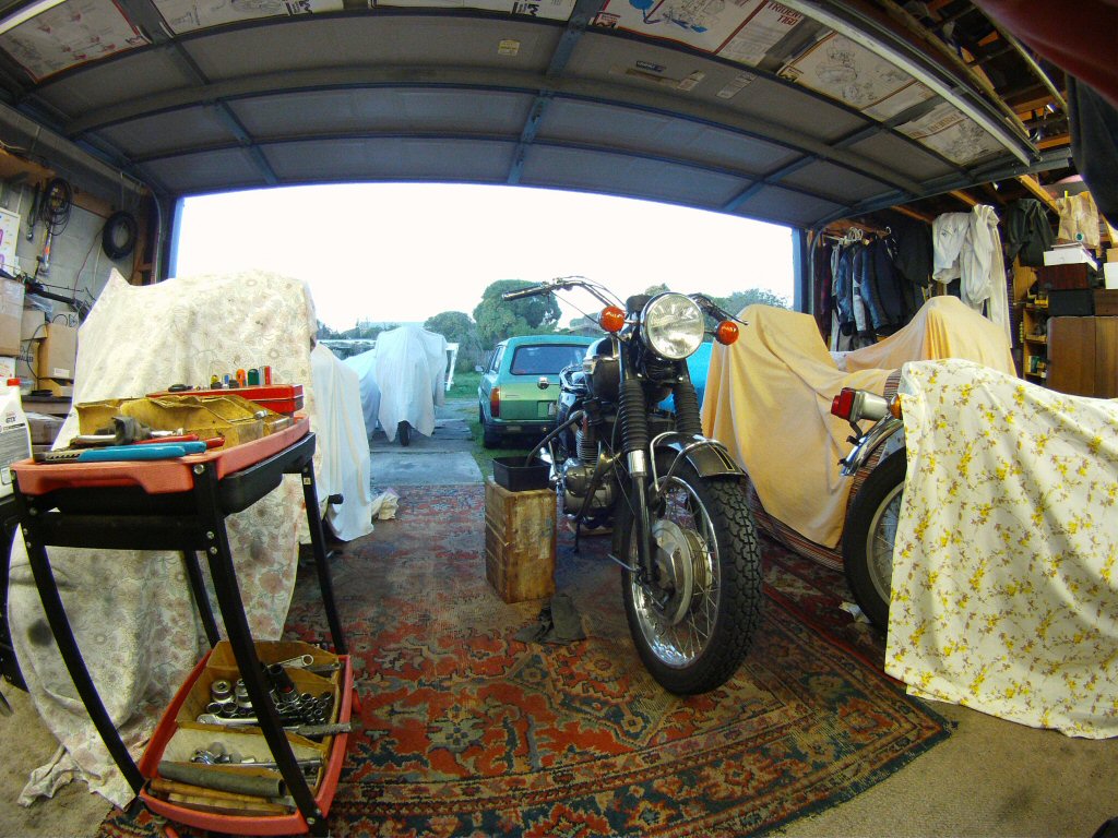
A frosty start today turned into a fine afternoon, so I set things up to do the second start. Very strangely, I got no fuel from the taps, having turned them off while the bike was still running yesterday, and I had ensured that fuel was coming from both taps during my initial fuel check. I poured another half a gallon into the tank, which was not empty, and now we had delivery from both taps. Hmmm. I suspect that this bike has two 'main' fuel taps fitted, which have a pipe inside their filter whose purpose is to leave the reserve fuel so that only the reserve tap can access it. So this bike runs out of fuel on both taps simultaneously and the remaining fuel is just a tease...
Not the best move.
The bike was a little less eager to start today as the air was colder, but it did so, and a quick look with the strobe light showed the ignition timing was a bit retarded c'est moi. A quick 'about there..' adjustment and the next strobe showed it to now be spot on. Was ready for a bit of luck.
A brief warmup after that until it would idle consistently and I ran around the pilot air scews, and all the carbs wanted more fuel, so they got less air. This will improve the cold starting methinks. I had also noted that while the centre and right carbs took some time to tickle before fuel appeared, as is usual, the left side produced fuel immediately, meaning the fuel level was higher. This was echoed by the air screw, which wanted more air than the others. I had checked the float levels when the carbs were apart and adjusted the floats then, so this one is somehow now at odds with those settings. I shall take the float bowl off and find out why.
As the bike warmed up today there were puffs of smoke from both exhausts when revved, which can be forgiven until the rings have heated up at least once, but it is unusual with the piston/ring combination I am currently using. Then I remembered how oily the pistons and valves were when it came apart, and I think this is oil burning out of the exhaust headers. The fact that it had virtually ceased by the time I shut it down today makes that look the most likely cause.
It kinda went like this.
While I was waiting for the oil light to show up, an indicator of how well the pressure was being retained, the camera ran out of memory and turned off. I gave up waiting after 45 seconds with some doubts about the oil pressure switch. There have been a lot of failures with the latest crop and this appears to be one of them. I bridged it out with a piece of wire and the light came on, so the switch is definitely dicey. I shall see how it behaves over the next runs.
Tomorrow when the engine is cold I will finalise the head tension and whatever else that involves, and tidy things up before the tank gets its final fit. It was just sitting in place today and managed to add a few audible vibes to the plot.
All good progress.
Today being another fine day I made space in the shed and continued progress. The cylinder head got backed off and retensioned, with only the merest signs of any change. I checked the valve adjustments anyway, but could not improve on them, which is a testament to using solid gaskets in all joints through which the head bolts pass.
The head steady went back on, after which the oil lines, wiring harness and plug leads were moved around until finding the layout which gave best clearance to the fuel tank locating.
Finally the left side carb float bowl was removed to check its settings, and a slight adjustment made to the float level. It appears that the tickler on that carb may depress the float more than the other two, so things just happen faster when tickling. Some debris present in the bottom of the bowl which could possibly have inhibited the needle jet, but at least I got to remove it.
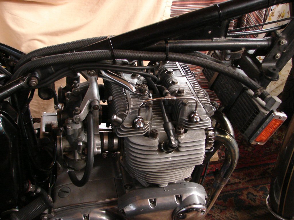
Next step will be to refit seat, tank and airfilter, and do a brief test ride. As the engine will be at full operating temp on return, the airfilter will come off again and a vacuum gauge used to balance all three carb airflows accurately. Any signs of oil leaks or errant behaviour will be addressed after that.
I noted that the folding part of the kickstart lever has worn enough that it sags below horizontal when in use. This encourages one's foot to slip off the pedal under wartime conditions so it would be user-friendly to replace it. That and the fuel tap situation are currently the only nags.
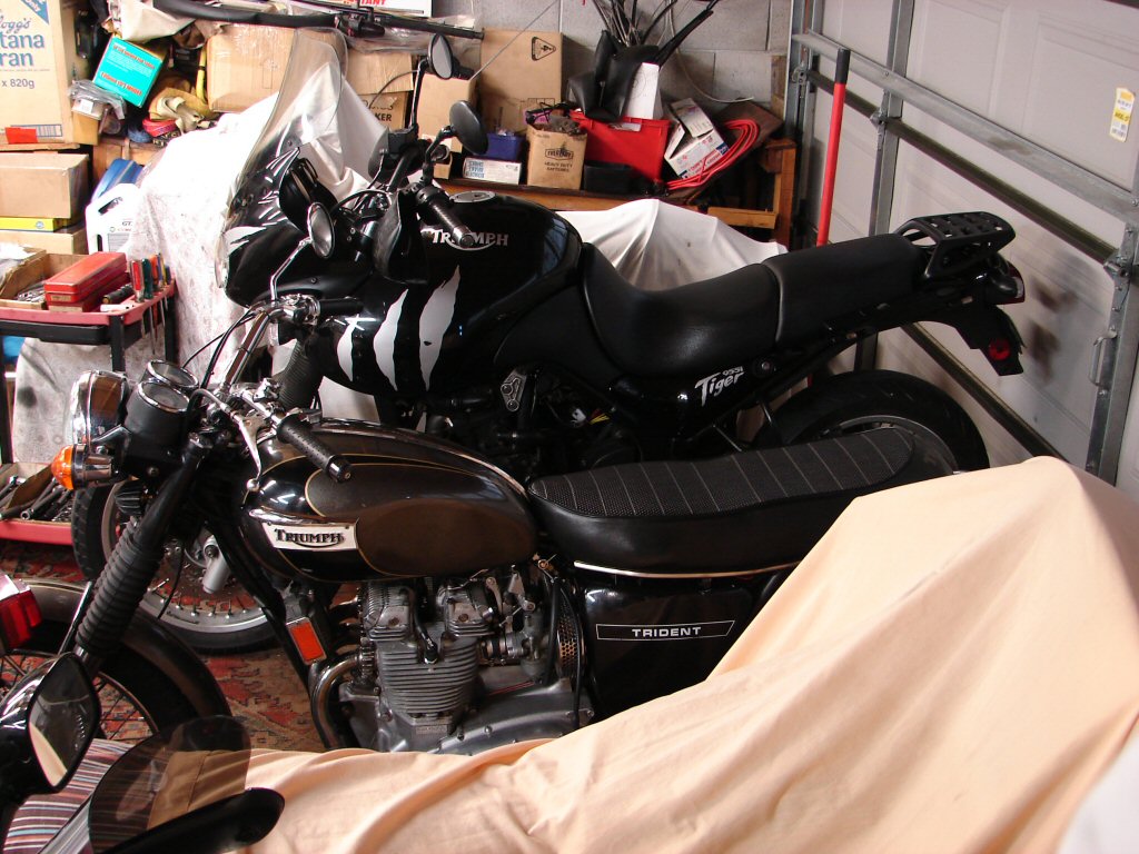
Today all the remaining bits went back on except the oil tank cover, which would need to come off again during the airfilter removal for tuning with the vacuum gauge. The fuel tank had a little resistance due to the thickness of the new wiring loom, but it finally agreed to play ball after the clutch cable got repositioned. It takes a bit of planning to ensure that nothing will get chafed or squashed in service if reliability is to be paramount.
The bike now moves to the front rank in anicipation of the first ride and some time and weather for that to take place in.
Meanwhile it looks rather dwarfed by the other current work in progress in the form of a later triple with some genetic inheritance..
A fine day today meant a test ride. Not wanting to risk any adverse events I turned the fuel on for some time before wheeling the bike outside. The right side carb flooded. I turned the fuel off, wiped up the spillage, then gave the offending float bowl a tap with a spanner. Fuel back on and now all carbs tickled correctly, including the one which used to seem too eager.
I then started the bike in the open shed, noting that it was more interested in starting than prior to the carb tuning, although it still likes a good tickle to elicit immediate signs of life. I wheeled it outside, closed the shed, donned helmet and gloves and started it again. All sweet. I pushed it backwards while astride the bike, then applied full left lock to line up with the driveway, at which point the engine abruptly stopped. A few attempts to restart revealed no life whatsoever. I then found zero electrics present. A quick look at the main fuse showed it had blown quite conclusively. Some form of short circuit had taken place and I assumed that it was probably related to the full lock application, whereby much of the wiring behind the headlight gets considerable movement. I wheeled it back into the shed and proceeded to remove the headlight.
This bike is going to fight all the way.
The mass of wires behind the headlight is totally inaccessible until the entire headlight shell is removed, so I went straight there. There is a spare terminal on the ignition switch which is bare, so I had wound insulation tape around all the terminals previously, as the tacho cable is very close. I had also taped the upper steel sleeve of the tacho cable for the same reason, and could not see any sign of a splash on either surface. So I moved the connector from the inner terminal to the outer, as it has a sturdy plastic cover over its spade connection.
Delving further I found another plastic covered terminal which once went to the zener diode, now defunct because the bike has an electronic regulator/rectifier fitted under the seat. While it did not seem possible that anything could have made contact with it, I considered it a prime suspect as it comes directly from the fuse, and I am aware that the headlight shell is pressed up firmly against all the wiring here. So I cable tied that terminal out of the way, and included the flasher unit in the process, as it has a bare metal can which under the most unlikely circumstances could possibly short two things together. Obviously something had for the fuse to have blown in the first place. I also wound the can with insulation tape for good measure.
When I rewired this end of the bike I had run the indicator lamp wires all the way through the headlight shell and into their respective lucas connectors behind, but this now proved to be the cause of some fiddling when removing the headlight, so I now fitted another pair of connectors inside the headlight which will also make it easier to remove either indicator lamp without disturbing the headlight completely. I feel happier with that arrangement now.
With everything back together I fitted a new 35A fuse and started the bike, which it did happily. I then moved the bars lock-to-lock several times and the motor kept idling happily, so hopefully one of those items was the fault and is now cured. When test riding I make increasing radius orbits around the local roads so that any fault that might kill the engine in the early stages of testing does not result in too greater push to get it home. I should be pleased that I did not even get it out of the drive this time. I shall still play it canny next attempt.
I will make a note here that the Amal premier carbs as fitted to this bike have a different type of float compared to the original carbs the bike would have come with. I have had a number of unpredictable carb flooding events with the premiers, all of which respond to a tap with a spanner or screwdriver handle, which indicates that the floats get stuck to the inside of the float bowl when the bike has been sitting. With stationary running the carbs can get warm due to the lack of airflow, and the fuel probably evaporates off quite quickly, especially as I am in the habit of running the engine for a short time after turning the fuel taps off. We will trust that it was a one-off event this time.
Will soon see.
An opportunity presented itself, so the bike got wheeled out and fuel turned on. I waited some time until I was happy that there were no unexpected floods, but it was all as it should be. It started with a couple of kicks and I was able to keep it running until it showed it was happy to accept throttle and rev. Off we went around the usual test roads, noting anything that would need adjusting. Like the rearview mirror. Rear brake felt underwhelming but the front lived up to its reputation and took care of business.
Clutch cable needed a small amount of tightening to make neutral easy to select, but otherwise the bike rode very well and showed a snappy throttle response, which also pleases. No sign of any smoke from exhausts, so the pipes have baked themselves dry.
Back to base and adjust the idle now it was hot, after which a quick run around the pilot screws showed that we were still spot on with idle mixture. A good look around the bike and not a drop of oil anywhere to be found. Bodes well.
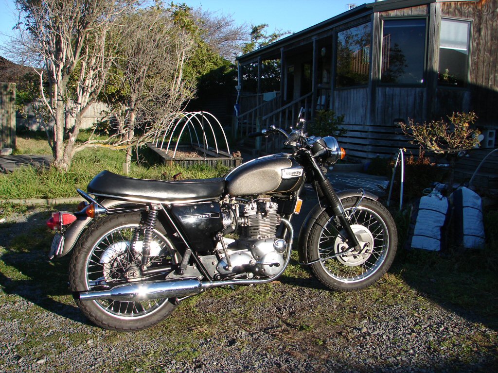
Today being both Saturday and a warm day after a major frost it was prime time for testing a few bikes. The Trident was second on the rank, so I got in my stride on a Tiger first, and noted that it was quite a handful compared to a low classic.
The Trident came out in the sun, and fired up quickly, then settled to idle almost straight away. Amazing the difference a few degrees extra warmth make. I rode a bit further this time, with a stretch of 80Kph included so I could explore a few revs. The bike pulls cleanly and healthily up through the revs, and you can't ask more than that. I ride the bikes exactly the same when new or well used, mostly between 3000 and 4000rpm, as they do everything you need within that range. It handled it all without a niggle and I was soon back to remove the airfilter and use my vacuum gauge as the final tuning measure. The three carbs were quite at odds with each other, which only goes to show that there is a lot more going on than just the height of the slides is responsible for. It usually takes about four goes to get them all even, as each alteration to one effects all, so round and round you go. When its right its right and I do my usual test exercise of hands-off starting.
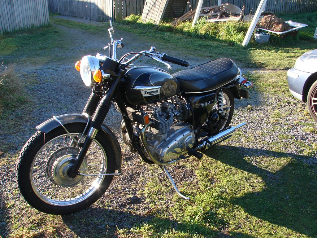
Now for the acid test - at operating temperature of course...
I figure that I can't improve it any more if it does this.
Seems that it does. I checked the primary chain tension, which is still perfect when hot, and I shall remove the oil pressure light switch to see if I can clean it out in any way to encourage it to work properly. If it fails to come on when the pressure runs out then it is totally useless. The kickstart lever works well enough once you're used to it, so while I would have to replace it on my bike, I shan't throw $60 of someone else's money at my neverending search for perfection.
Surprisingly the oil light switch responded to CO contact cleaner and began working correctly after a good flush. I had better not write them off too soon in future.
Being as far completed as I could manage right now the bike was collected by the owner and taken home. I received a text today reporting that a 40 mile run was taken today and all is well.
Sweet.!