July 2024
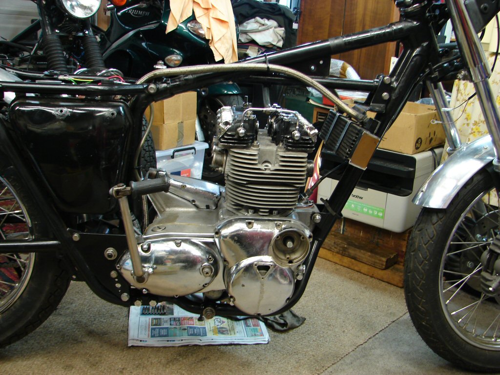
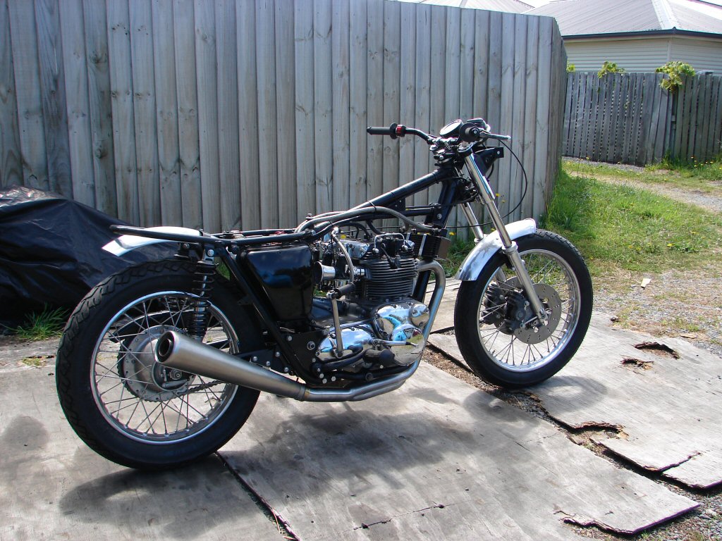
1973 Triumph T150 Trident 750
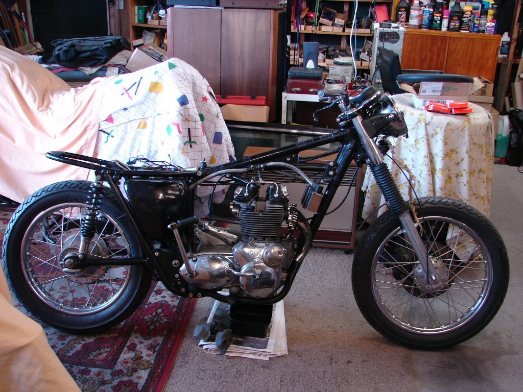
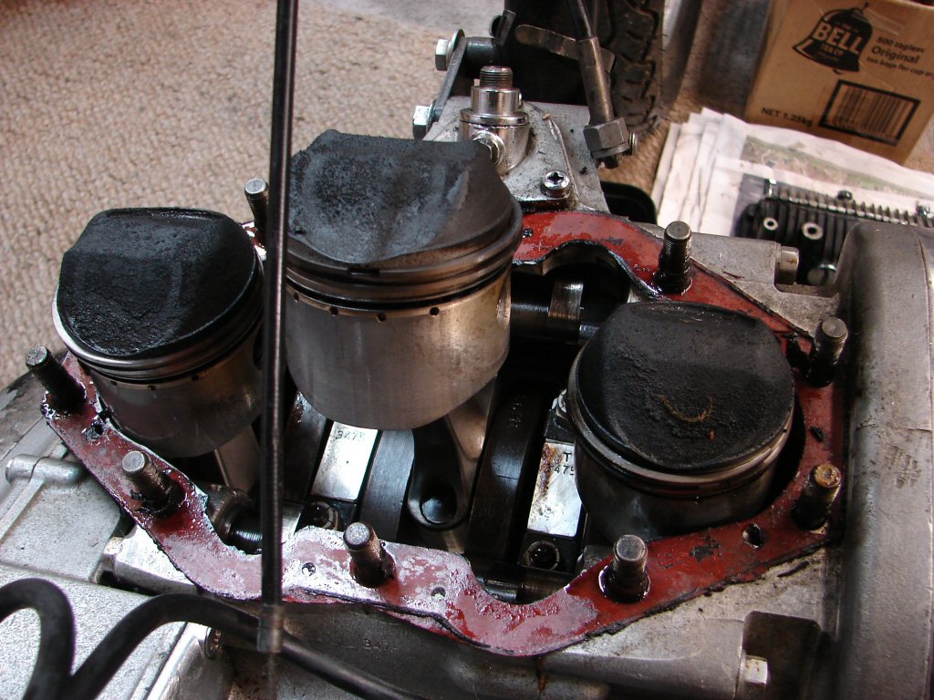
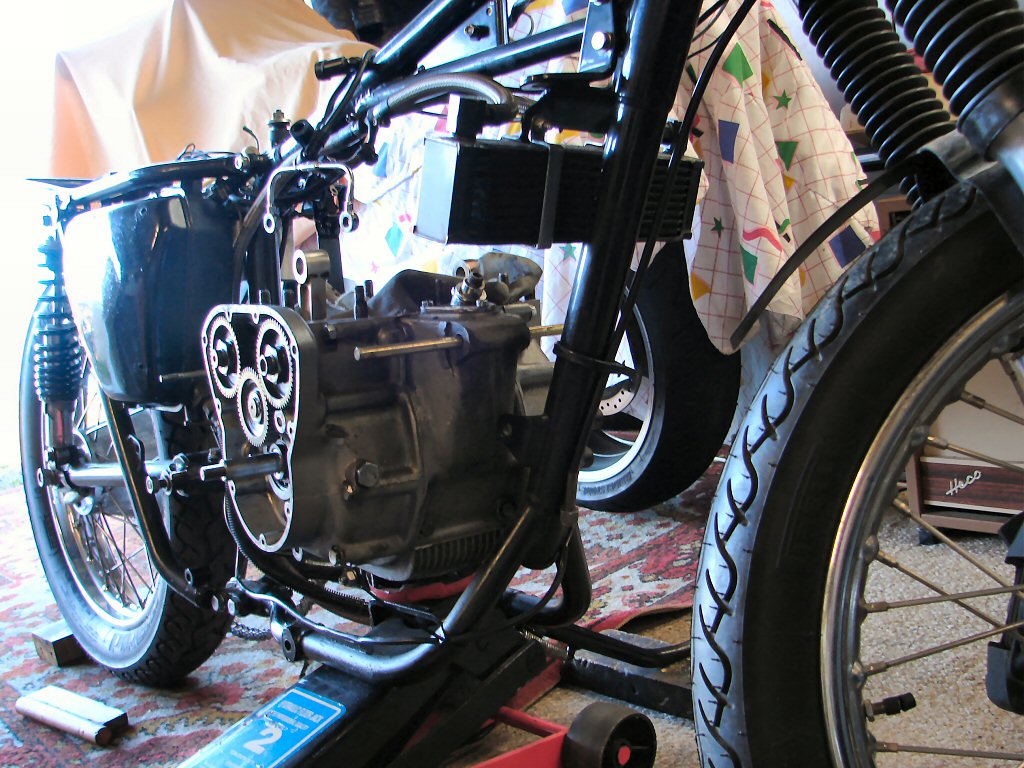
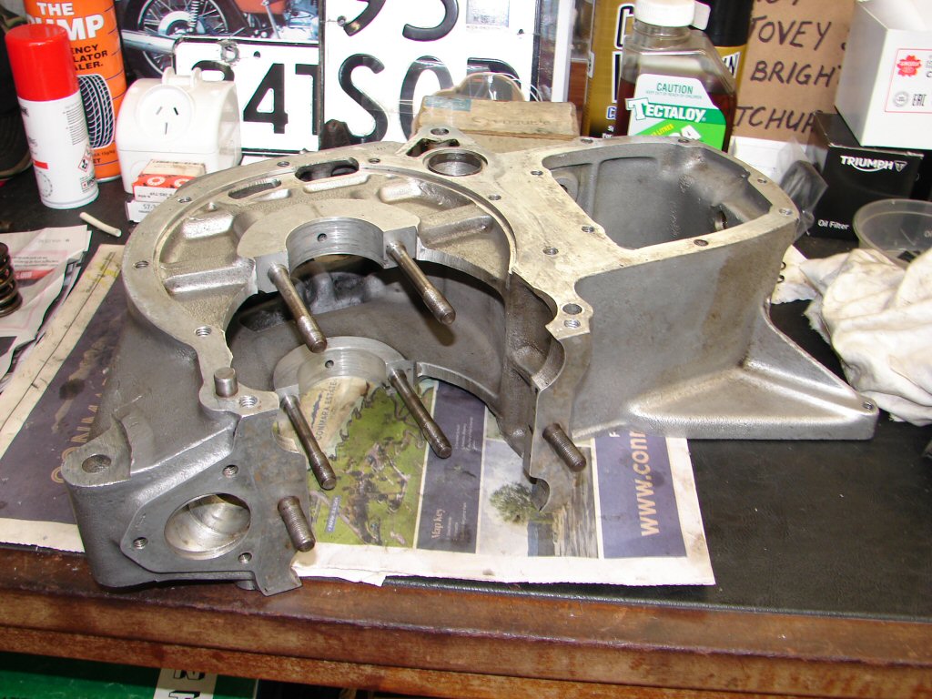
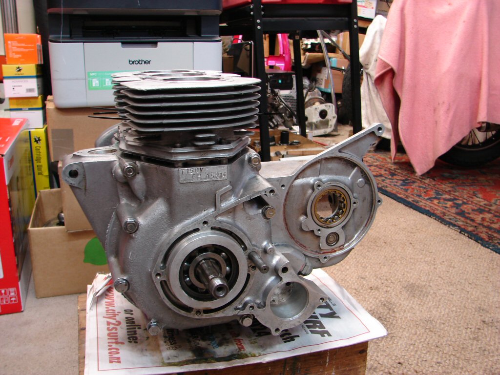
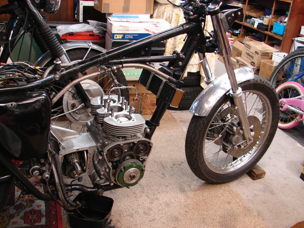
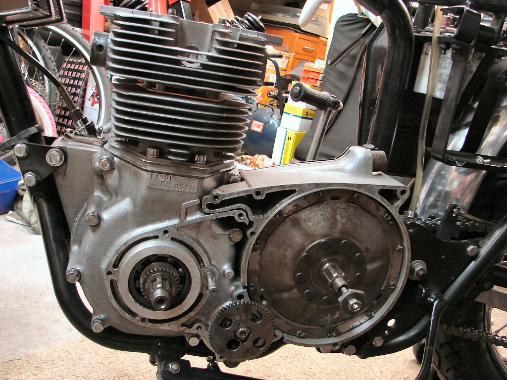
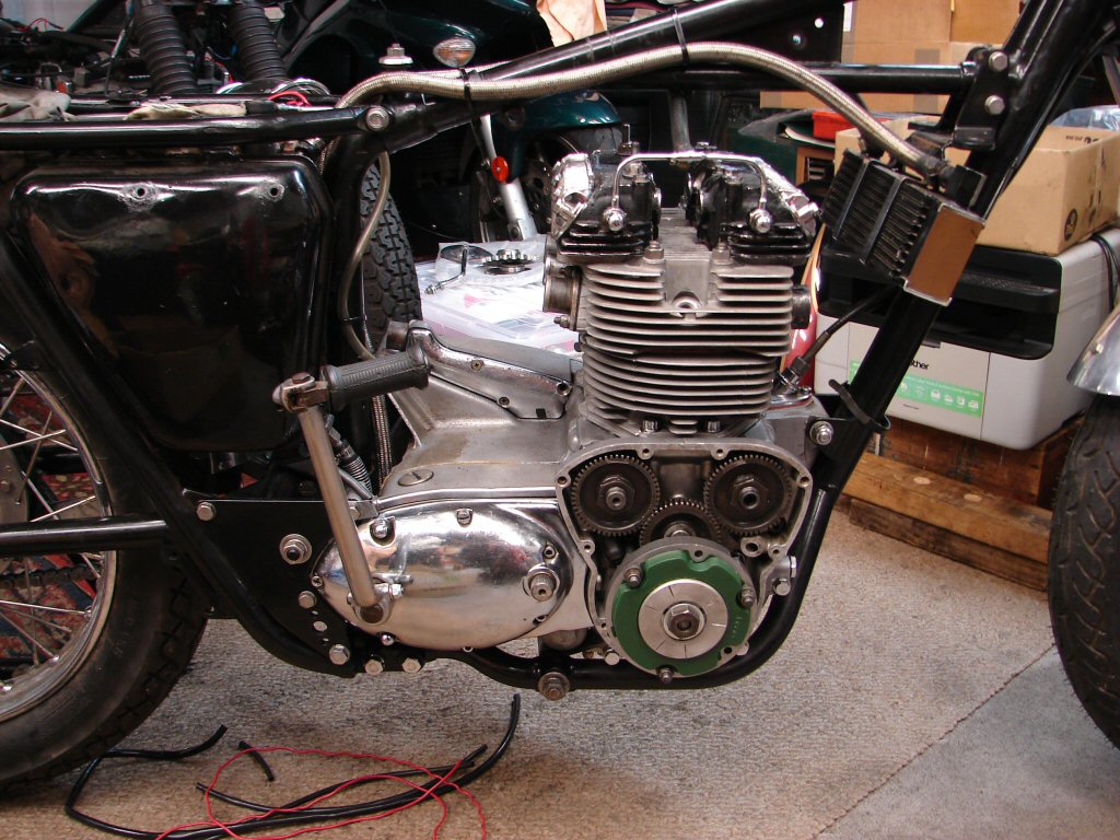
Acquired as a potential race bike, it soon became apparent that the engine of this T150 was locked solid. The clutch and primary drive seemed to be functioning normally, so the crank was the major suspect.
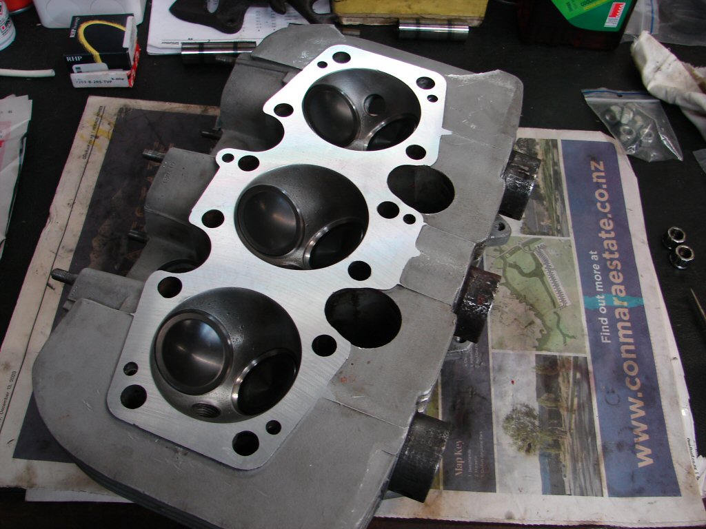
The head came off nicely, although a few head bolts were not tight, so hopefully this does not indicate stripped pillar bolt threads. Evidence of quite a lot of sealant around the rocker boxes, and it looks to be quite fresh.
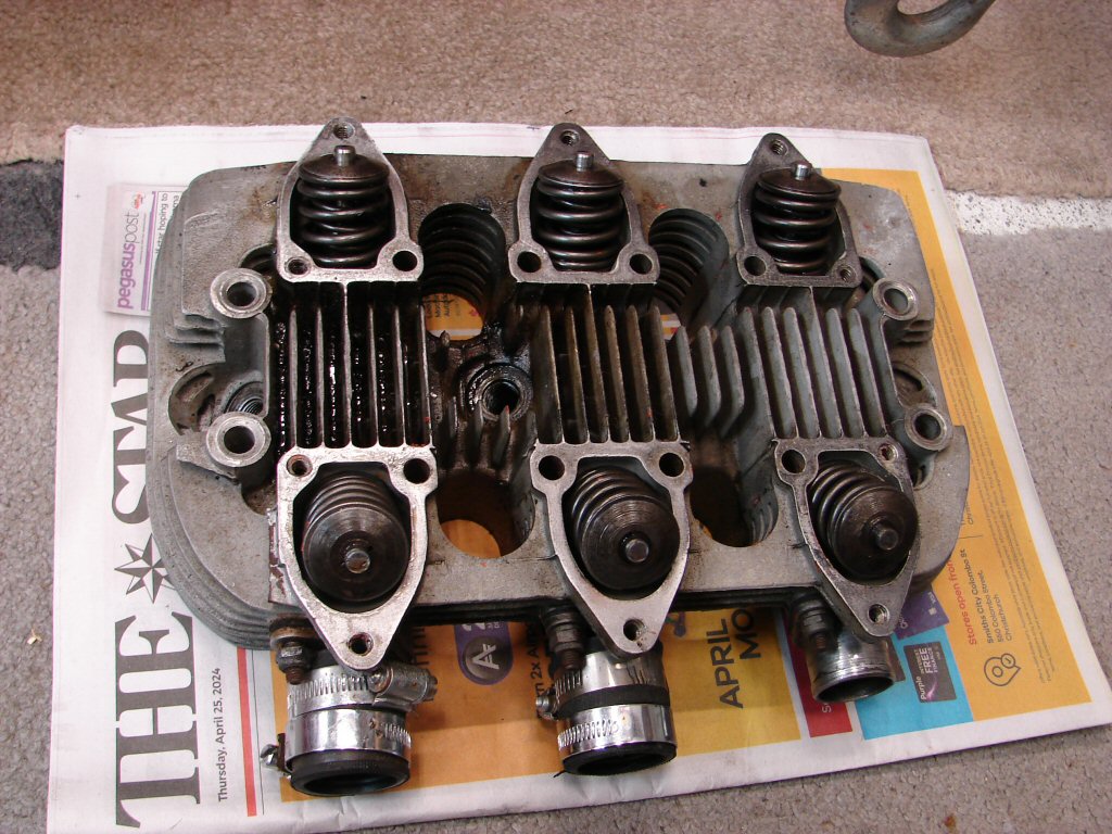
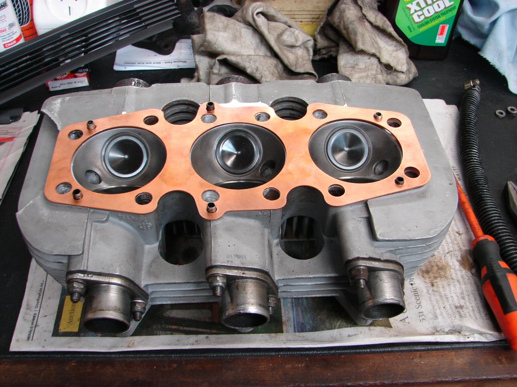
Apart from a good coating of carbon, the valves and combustion chambers looked to have led a fairly trauma free life prior to the bike being laid up. Valves and guides will be vetted during eventual reassembly, but everything looks to be in reasonable condition.
The current owner bought the long stored bike as-is and had been putting diesel down the bores to free it up, but my opinion is that they don't seize up in the shed - they go into the shed seized up.!
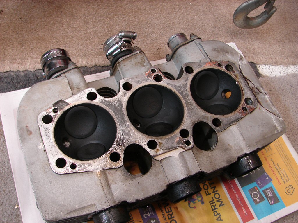
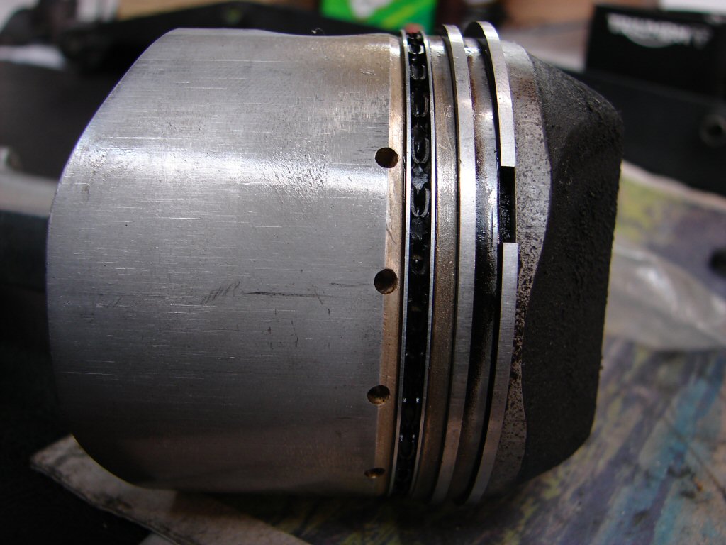
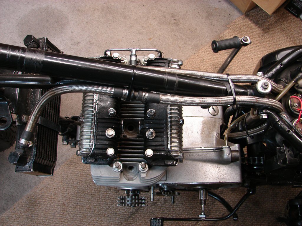
Sure enough the barrels came off without any great effort, so obviously the pistons were free in the bores. They also felt to be quite firm, which suggests that things are not too worn. Perhaps a hone and a set of rings would provide a good enough result for its intended purpose.
Cam followers and cam lobes also looked to be in good working condition, so a lot of good signs but no obvious explanation for the seizure symptoms yet.
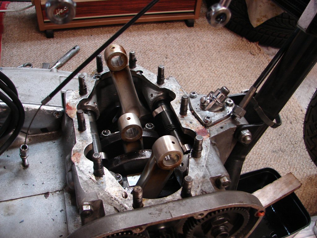
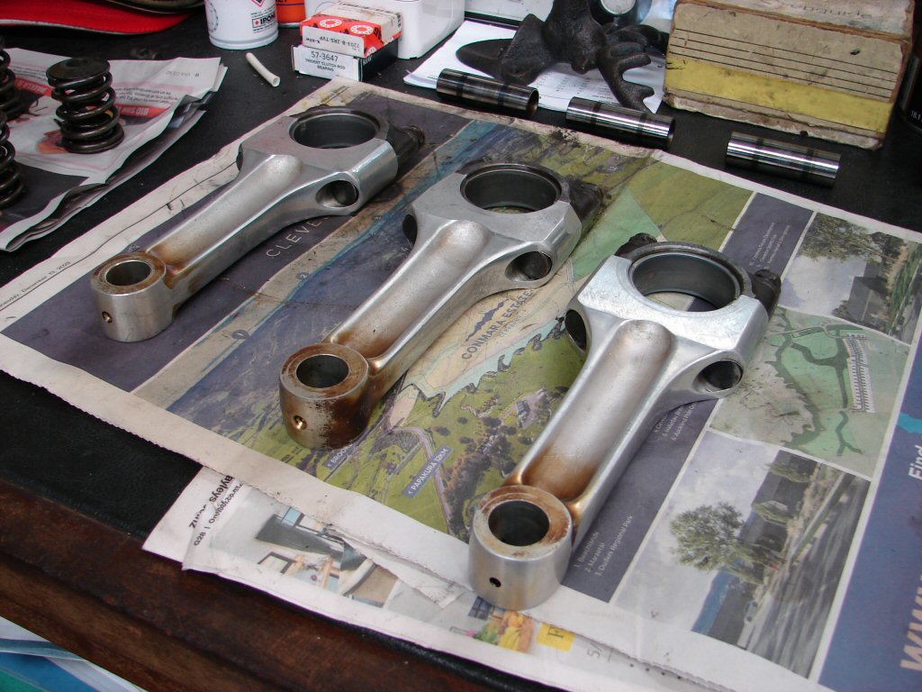
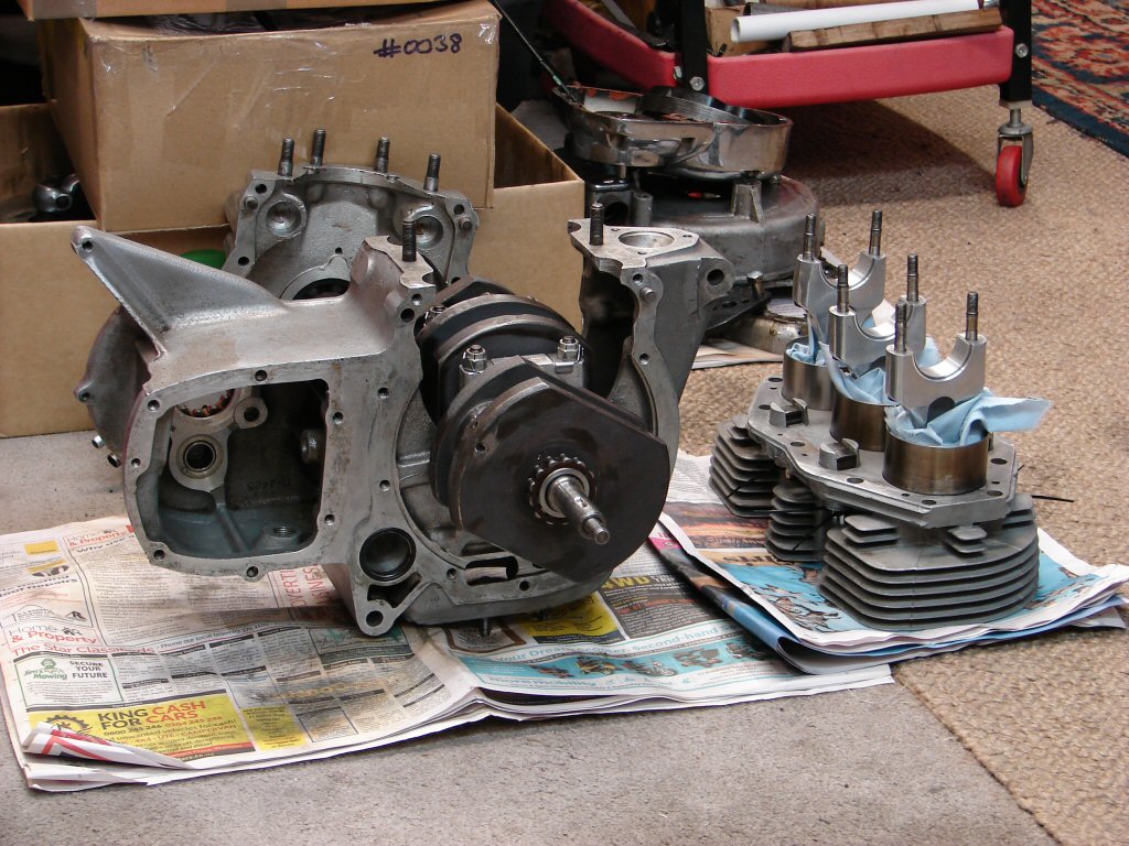
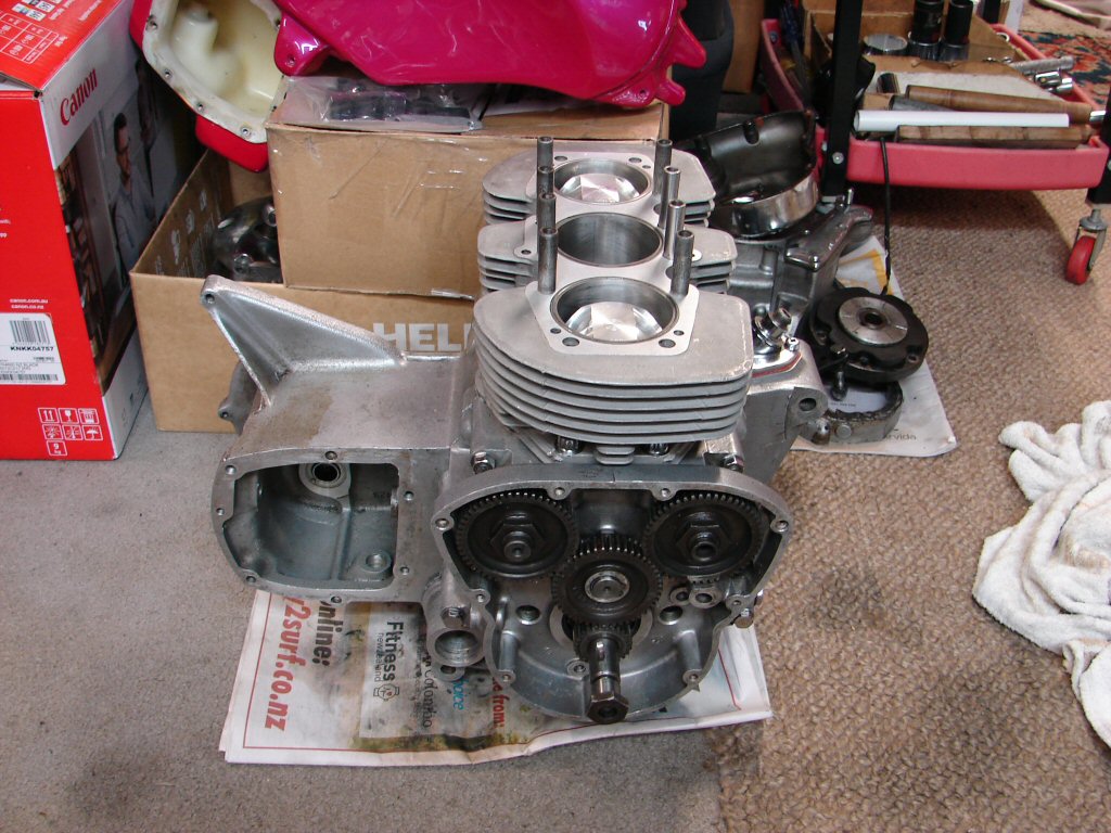
Investigating the conrods revealed the problem, although leads to some doubt as to how serious things may be.
While the crankshaft can now be rocked easily to and fro, all three conrods are seized to the crankshaft. I do not feel that this seizure occurred during storage, especially as the engine would have wet sumped generously over time, but for all three conrod bearings to have seized simultaneously would suggest a sudden and complete loss of oil pressure if it occurred in use.
Stripping any further will involve removing the engine from the frame so that the end cases can be removed, and no doubt removal of the crank for any remedial work, but I am very curious as to what might have taken place.
It would be possible to at least remove the centre conrod without pulling the engine apart, even though it seems inevitable that it will have to come apart anyway, but can I wait that long to see what happened..?
Can I hell..!
Big end shells have not seized while while spinning from all appearances, so my only explanation is that they have not moved since being fully torqued up.
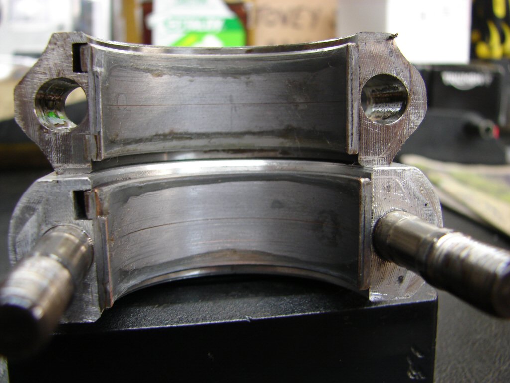
Crankshaft journal gives the same impression and may even have been recently ground.
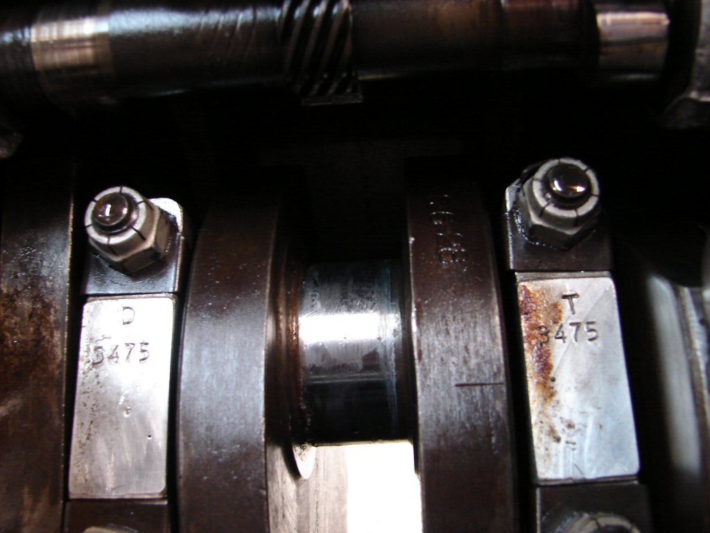
Bearing shell part number denotes -.020", so possibly the crank was ground to something less..?
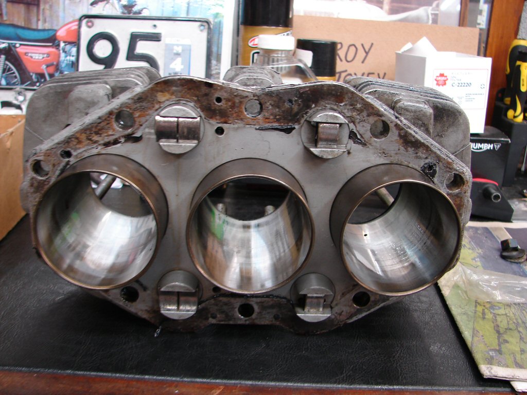
While pistons and rods show signs of significant usage, the piston rings could almost be quite new. Bores lack signs of any recent hone though.
The plot has thickened dramatically, but to our advantage. I will not know until the entire crankcase strip is completed what we have in the way of main bearing condition, although I know that the crank is free to turn as much as the seized conrods will allow.
There is some major story here I feel.
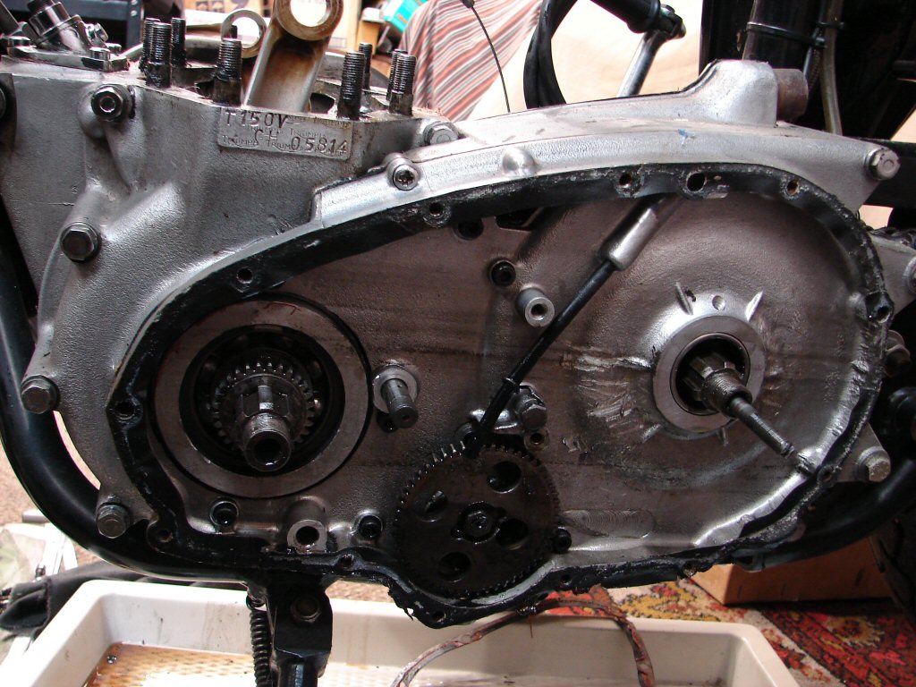
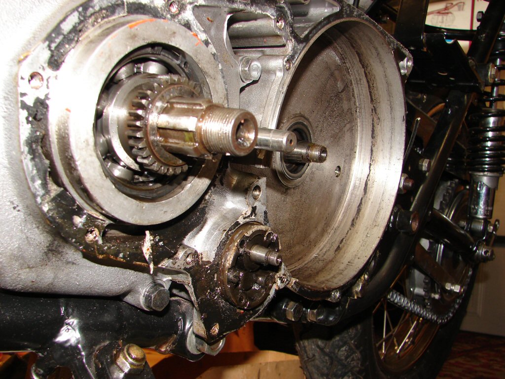
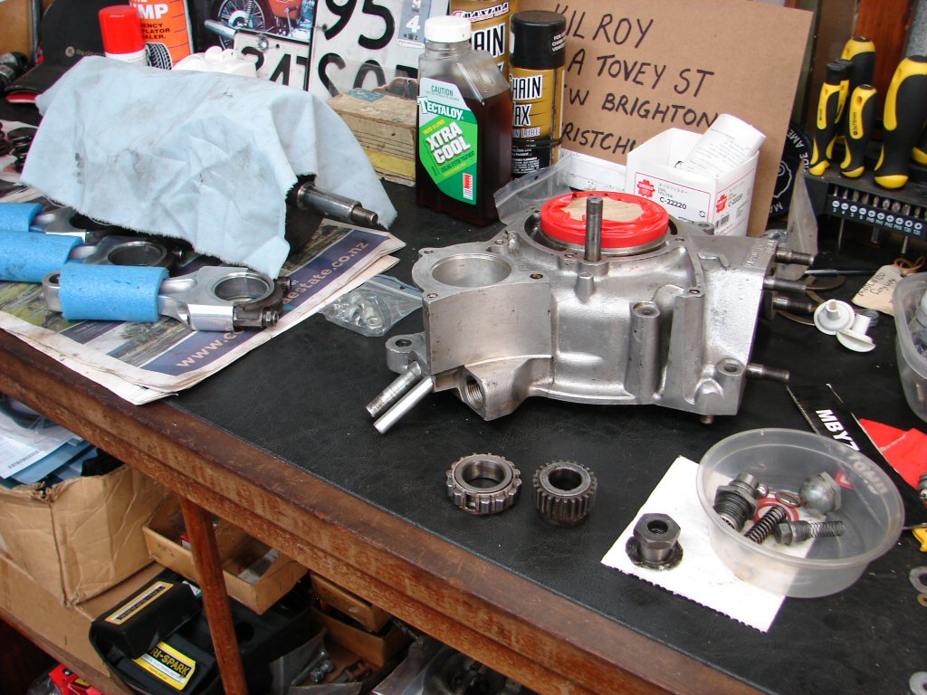
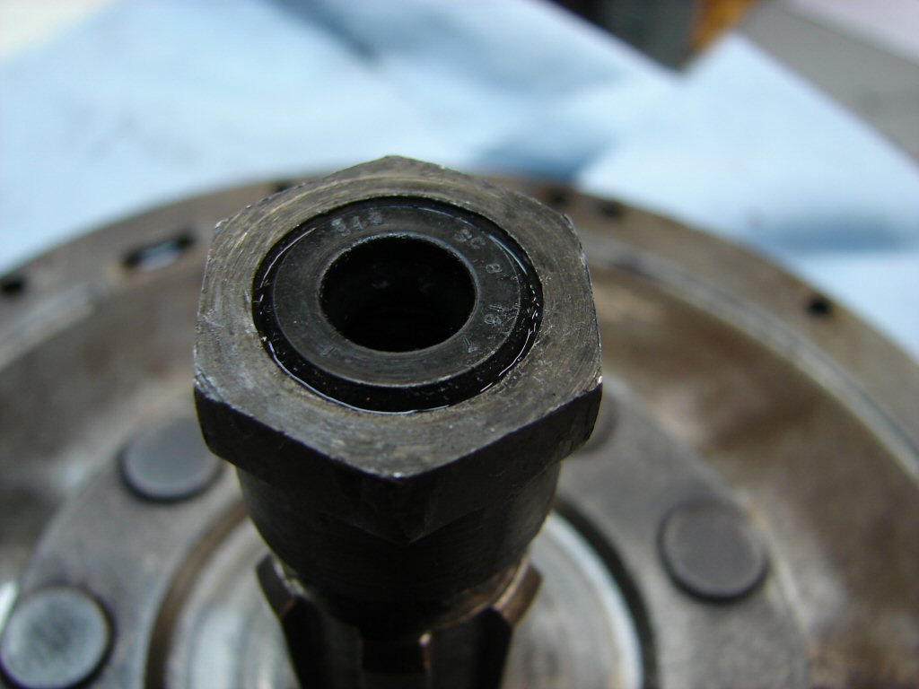
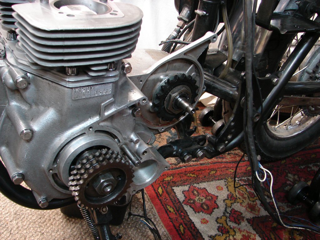
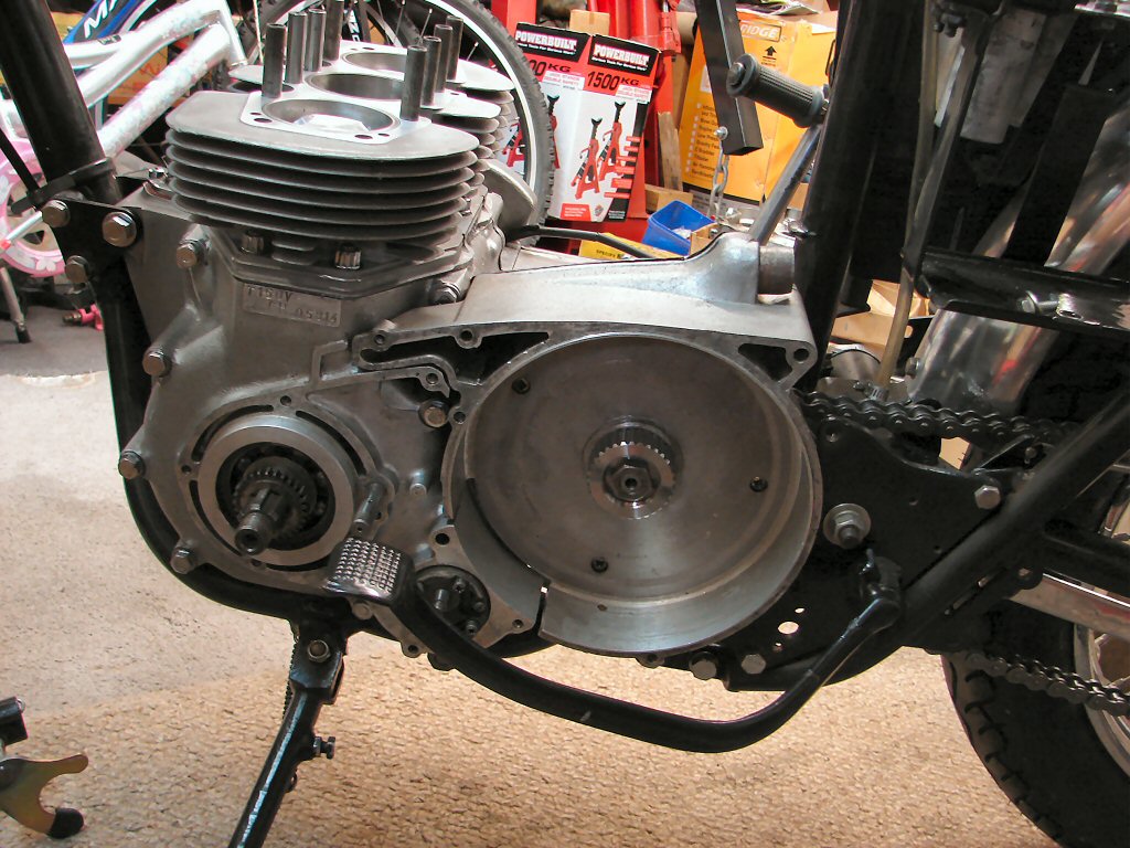
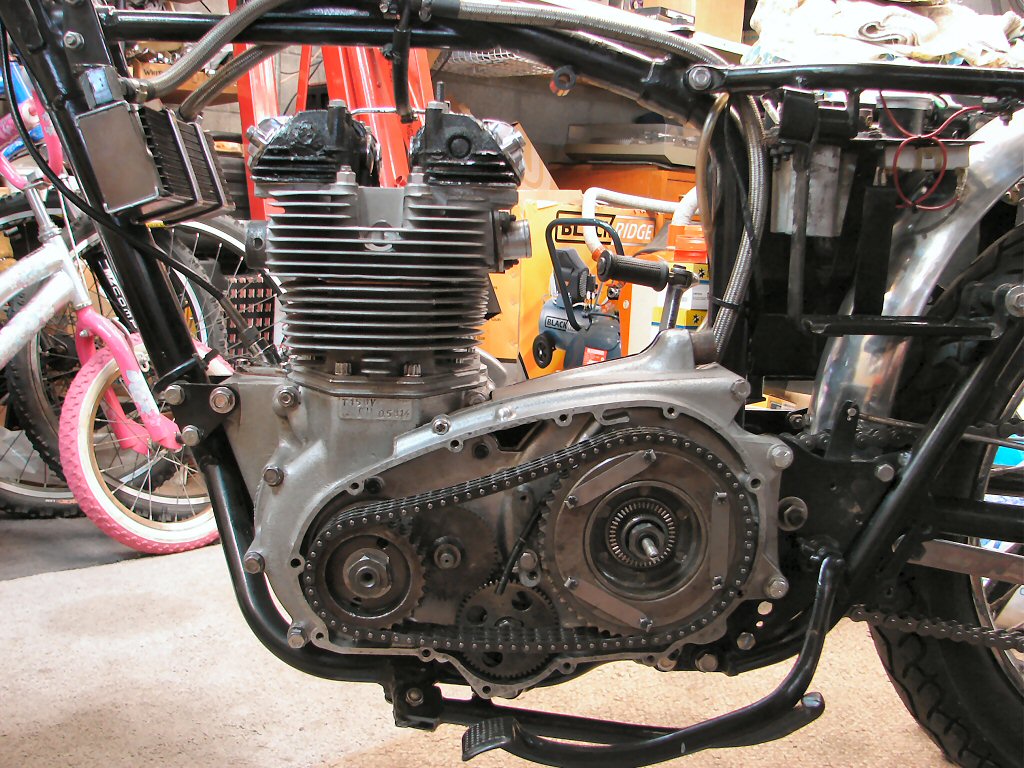
Meanwhile the dismantling goes on. The primary drive would be interesting as there was no way to lock the engine while undoing the crankshaft sprocket and cush drive nuts. The presence of glue in every thread hints that loctite would have been in the other pocket of the last builder. Sure enough, not only was the crankshaft nut loctited, but the locking washer had not been folded over, which is a shame as that is exactly why it is there. The cush drive nut seemed equally tight, so I would need to restrain the crankshaft in some way.
I refitted the centre conrod after removing all the pistons, to see if I could introduce a small block of wood inside the cases. Indeed I could at the lower rear, between conrod cap and inside of the case. With compression on that I used two power bars on the two primary chain sprockets - tightening one while loosening the other with the main target also compressing the block of wood. It worked, and the crank nut came loose. I then reversed the order until the cush drive nut loosened, after which I was able to loosen both by just using the block of wood.
The primary drive offered no further resistance, so the inner primary case will be the next to coax off. I may remove the oil pump first, with it's gear still in place, but only if it agrees to come out without a fight. That makes life a lot easier to get to grips with the clutch and it's housing prior to stripping the gearbox.
The oil pump drive gear could not be persuaded to move on its spline, so perhaps some loctite found its way there too. I shall engage a puller tomorrow after attempting the oil pump removal.
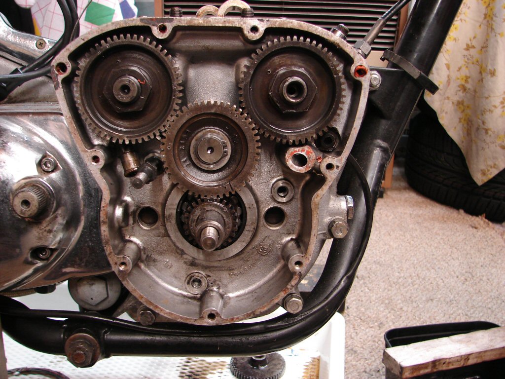
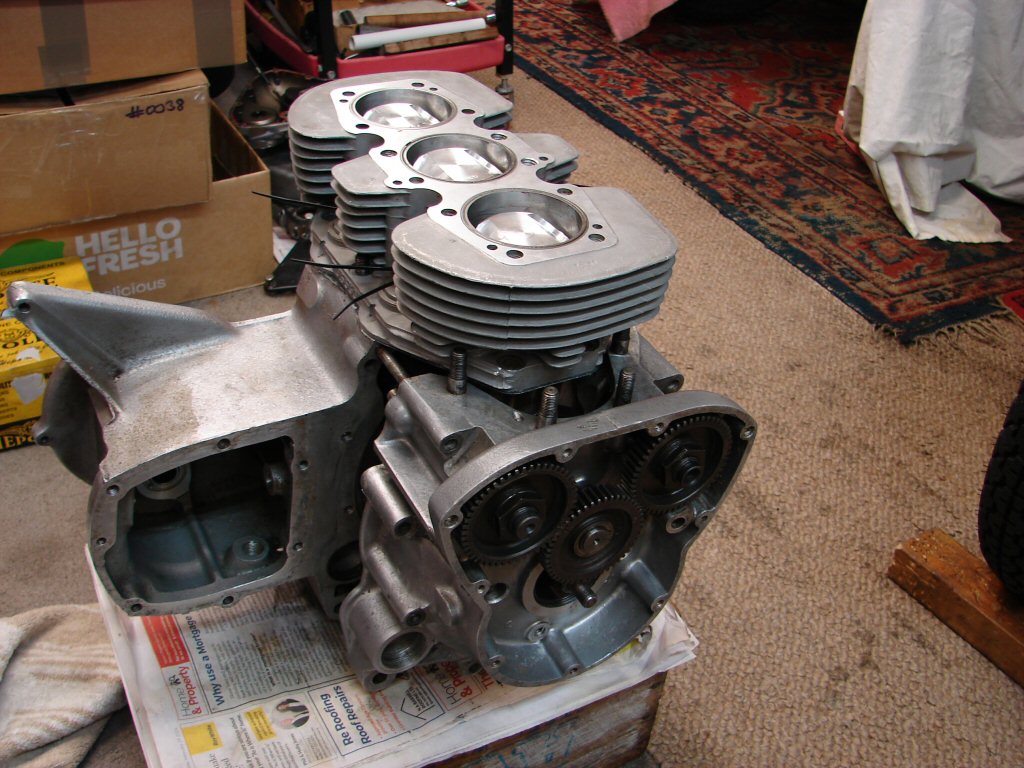
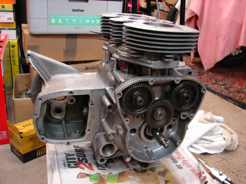
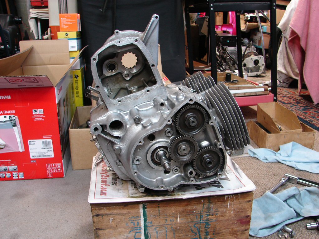
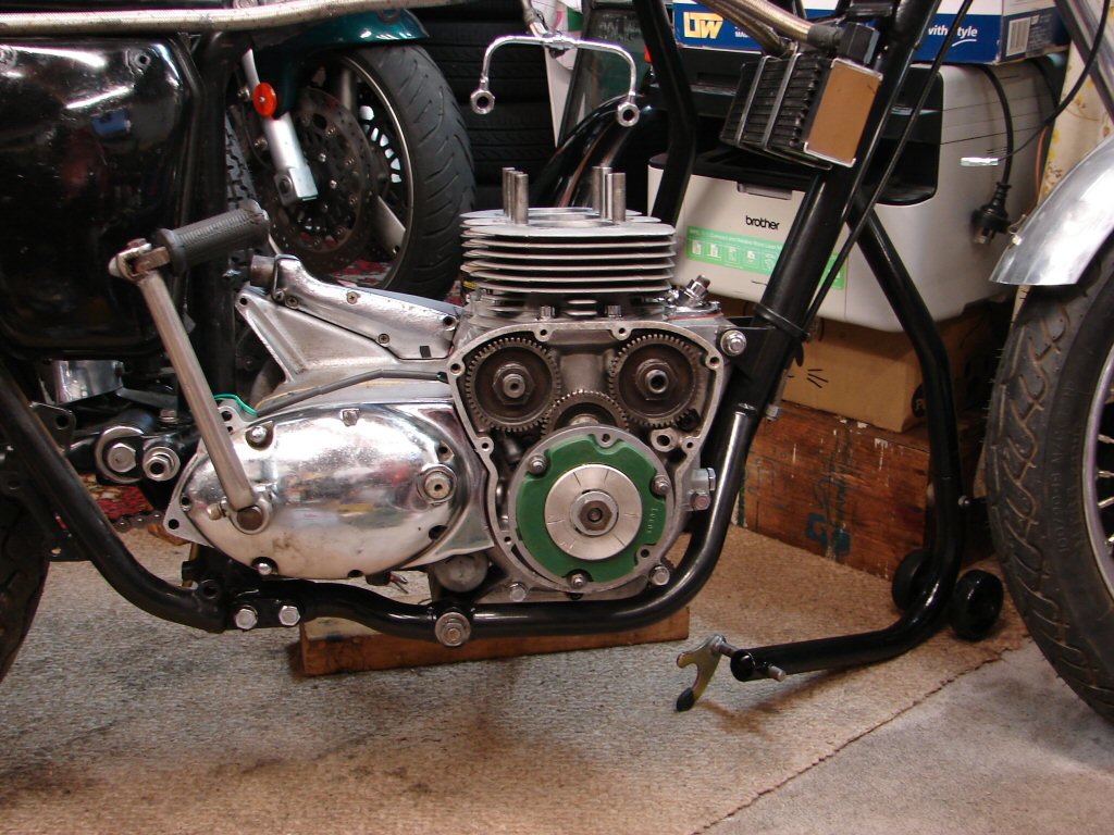
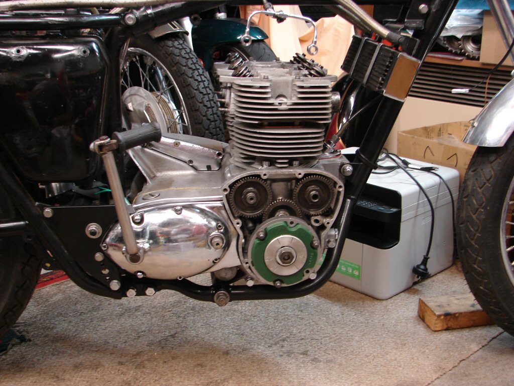
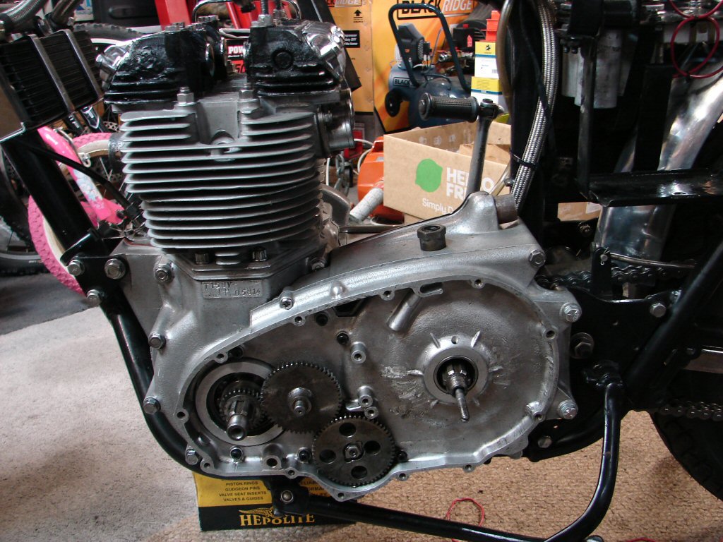
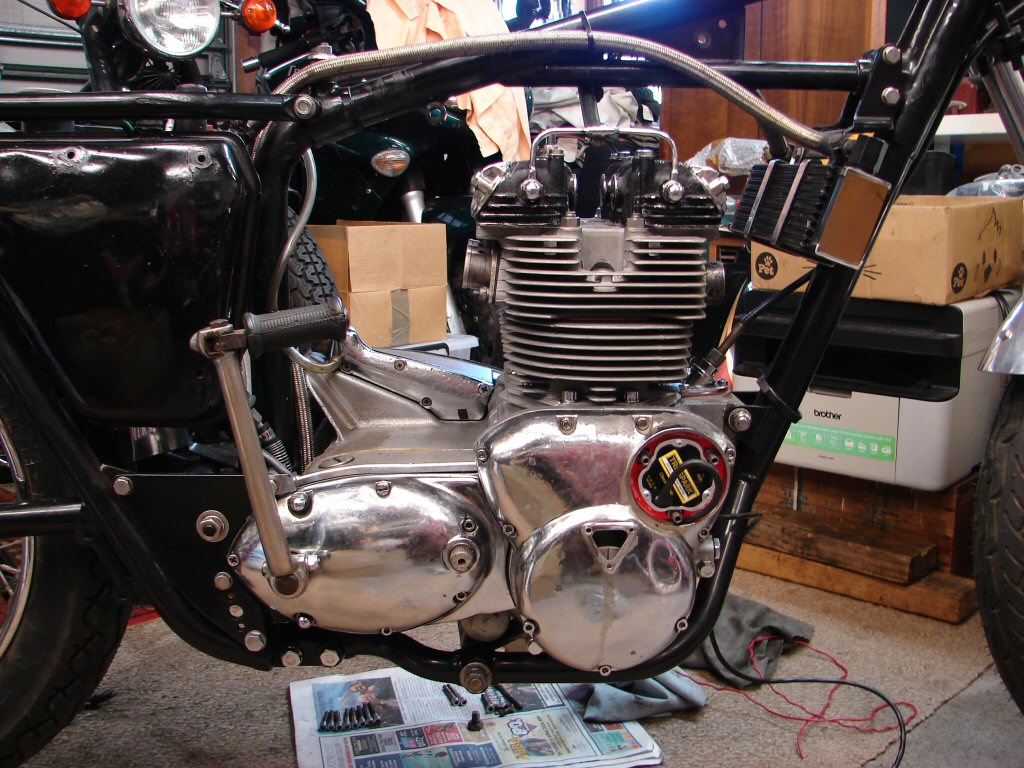
Last manoeuvre today was to strip the timing case, so the Boyer came out and the case screws were all deglued. The alternator appears to be fairly well cooked, so the wiring came out in several pieces. It might be possible to attach new wiring to it, but we shall investigate that when it happens.
I did not disturb the cam timing as I want to determine which marks were last used, and there are both dot and dash provided for the inlet cam, suggesting that only one is the optimum setting.
While not entirely hideous it has not been the most pleasing strip down ever, but there remains the doubt about why the rods are so tight. I was able to move the two outer rods using moderate force while positioning the crank, so while not completely seized there is definitely a dimensional issue there.
Oh what fun..!
There are times.
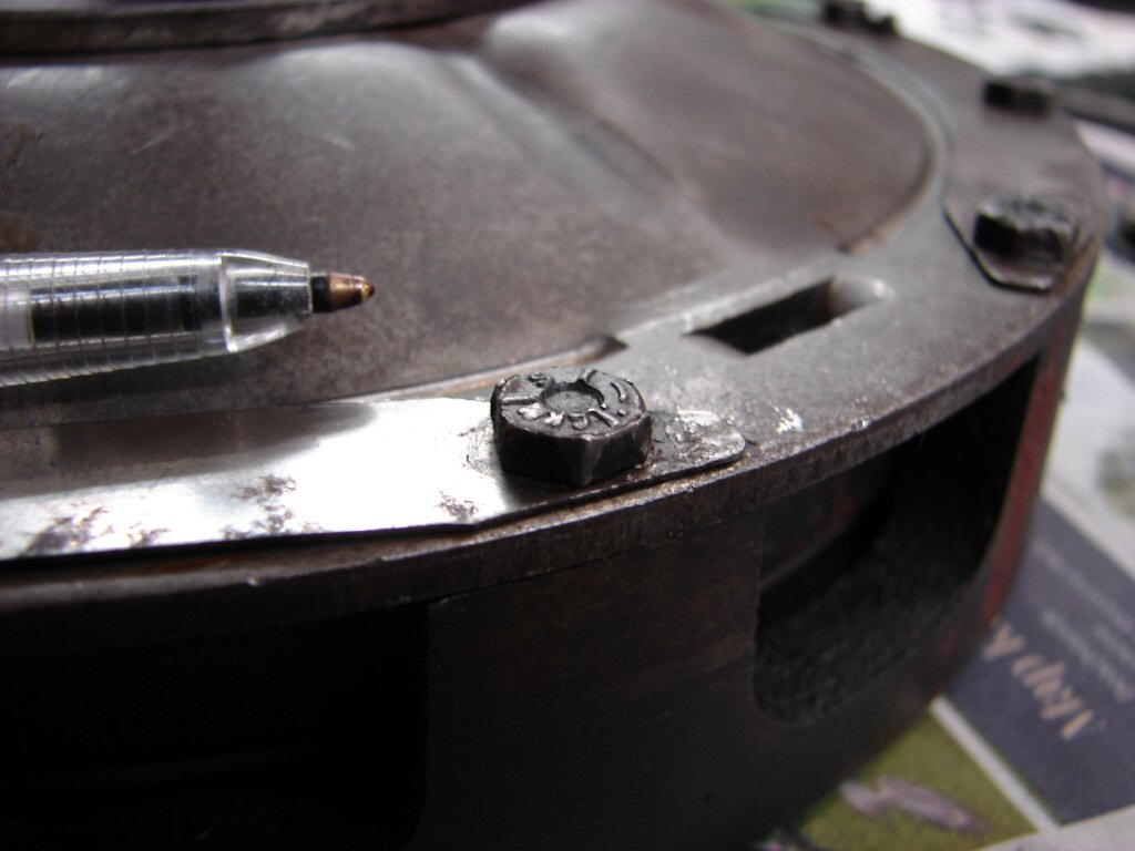
Removing the inner primary begins by attempting to remove the oil pump. That is when I find that all the gaskets are glued and the oil pump is glued into the block. Well that pretty much ensures that none of the parts we would like to remove will come off, but meanwhile, there are two very important fasteners in here which would really benefit from some sort of glue. One is the only large bolt inside the primary which holds the outer and centre crankcase housings together - but that is missing completely - and there is an all-important nut which holds the oil pump drive gear on to the oil pump drive shaft, but it neither has glue nor its purpose made locking tab washer.
Apropos of nothing in particular, all the engine mount bolts at the rear of the primary have two flat washers under both bolt head and nut. I am at a loss as to what purpose anyone could invent to make this a worthwhile arrangement, unless it was to provide a spare for the first washer which was probably going to get lost next time around.?
I have trouble comprehending why people with an absence of understanding of engineering principles would attempt to rebuild engines like this. Perhaps because it is a "small" engine it appears less critical, but if by any chance they had used the correct sized big end bearings I estimate this would have been a 'one-run' engine, and maybe have managed 50 miles before suffering catastrophic failure when the oil pump drive gear came loose.
It could have been much worse - I guess this engine has miraculously survived a suicide mission because it couldn't be turned over.!
Getting down to it...
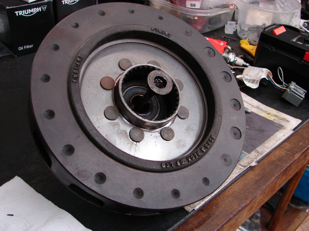
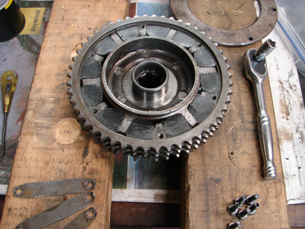
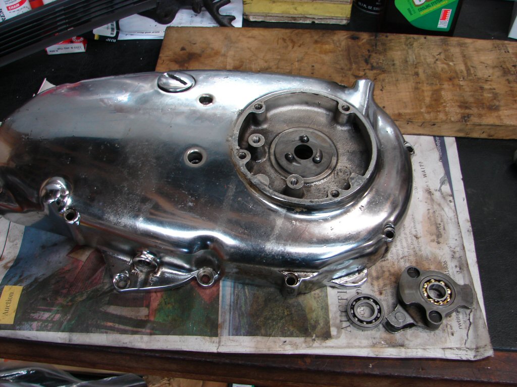
While showing obvious signs of oil stemming from failure of the cush drive oil seal, the clutch assembly is a positive ray of sunshine in a dark sea of substance abuse.
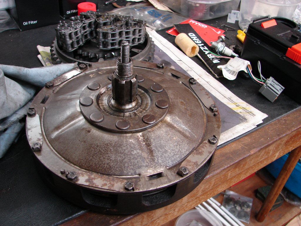
Not only but also - there seems to be a relatively new clutch plate in there. An odd mix of grubby and shiny inside this engine, like new bits have been fitted without any removal of old history.
Having removed the clutch assembly and housing I decided to be bold and attempt to remove the oil pump. A few gentle taps of the soft mallet were applied to the pump body before refitting the drive gear and applying a medium amount of force to and fro for some time. The pump is such a snug fit in the crankcase I doubted I was having much effect, but on the third try it suddenly slid out.
I consider that a major win.!
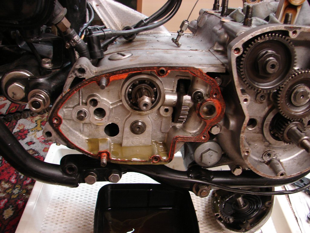
The chain and sprocket were left in place so that the rear brake could be used to lock things when the kickstart ratchet would have to be removed from the mainshaft. The outer gearbox cover fixings were all loose and at least one stud appears to be stripped. Surprised it had not leaked any gearbox oil - and there was a full measure in there - which had the look of weak porridge.
The gasket - I think there is one - had the usual amount of glue, a different colour this time, so perhaps this has been disturbed more recently than the rest of the engine unit. I removed said ratchet assembly and left it like this for the next foray - I currently have an Alfa cambelt to replace and car work has to be done outside, so a break in the weather has spurred me on..
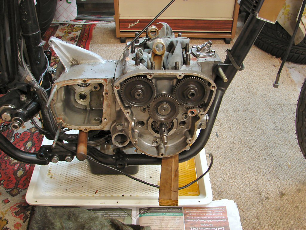
Back to the future, the gearbox inner case finally succumbed to my efforts and the expected glue proved to be stronger than the gasket. Once again, all the fixing screws and bolts were loose, and one almost suspects that two people were doing the build and neither did the final quality control.
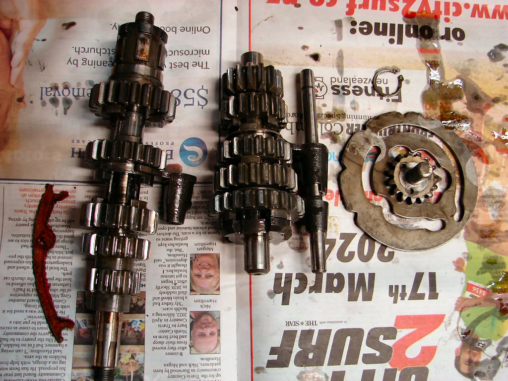
However, I was most pleased to be greeted with what appear to be quite low mileage gears and all in excellent condition. Selectors likewise, so it bodes well indeed.
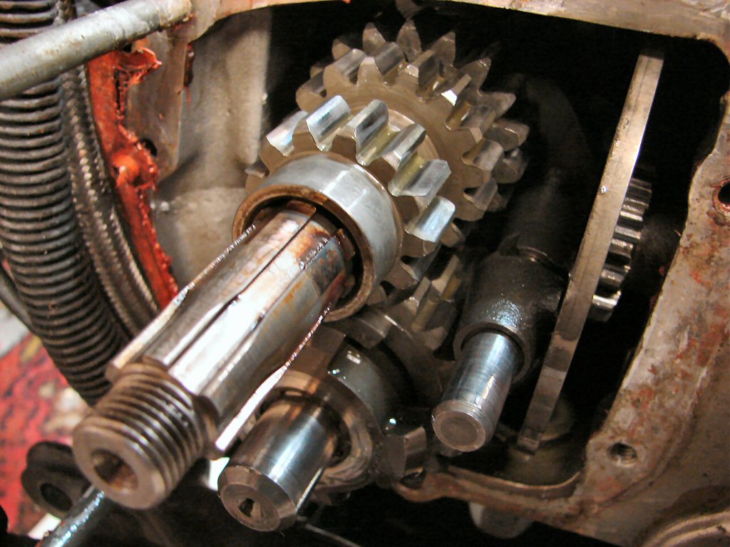
Removing all the gubbins as per the manual provided no surprises and it was all on the floor in short time. Now able to inspect things more closely I found that my first impressions were correct, so pretty much all of this will go straight back in with no qualms whatsoever.
It had appeared to be quite stubborn when I first started stripping it, but then I remembered that the supplement for the 5 speed gearbox is added to the back of the factory workshop manual, and yes , there is a circlip.
A bit of laborious cleaning later I had the unit ready to begin the removal from the frame, and I began by removing the engine mountings, and left the engine supported by a piece of dowel at the rear and a suitable steel rod propping the front by use of the remaining front engine mounting plate.
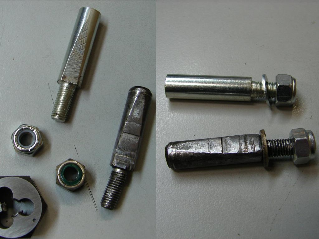
As with the rear engine mounting side plate, the threads were whitworth, and the long stud underneath was threaded its entire length and obviously owed its parentage to something other than a Trident. Perhaps some form of steam engine methinks.
It is rather difficult to lift the engine out of the frame due to the inability to get above it, and the lifting points are obscured by frame mounting bits which cannot be removed. With two people this is not such an issue, but I was keen to get the job done, as the frame was to be collected so that I had more working space in my shed.
I figured that if I could raise it up a few inches I would be able to rotate it enough to work from the right side, and I figured my trolley jack might do the business, especially as it has a rotating plate at the sharp end. I set it up on an angle so that my sturdy nail box would be parked alongside to plonk the engine on.
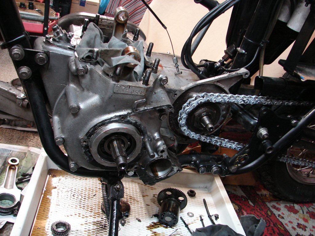
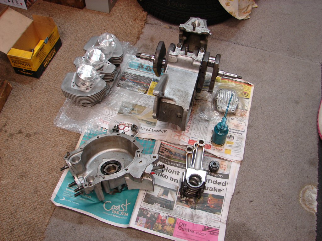
I thought I might still need another pair of hands, but after tilting the engine toward the right side I was able to lift it out quite easily and deposit on its new "engine stand". I will probably remove the two outer crankcase sections right where it sits, and am itching to see what I find with the crankshaft/conrod dimensions.
Although I strip the engine unit this far because the frame acts as the perfect working platform, the reduction in weight is such that doing everything by myself is much more manageable in the final stages.
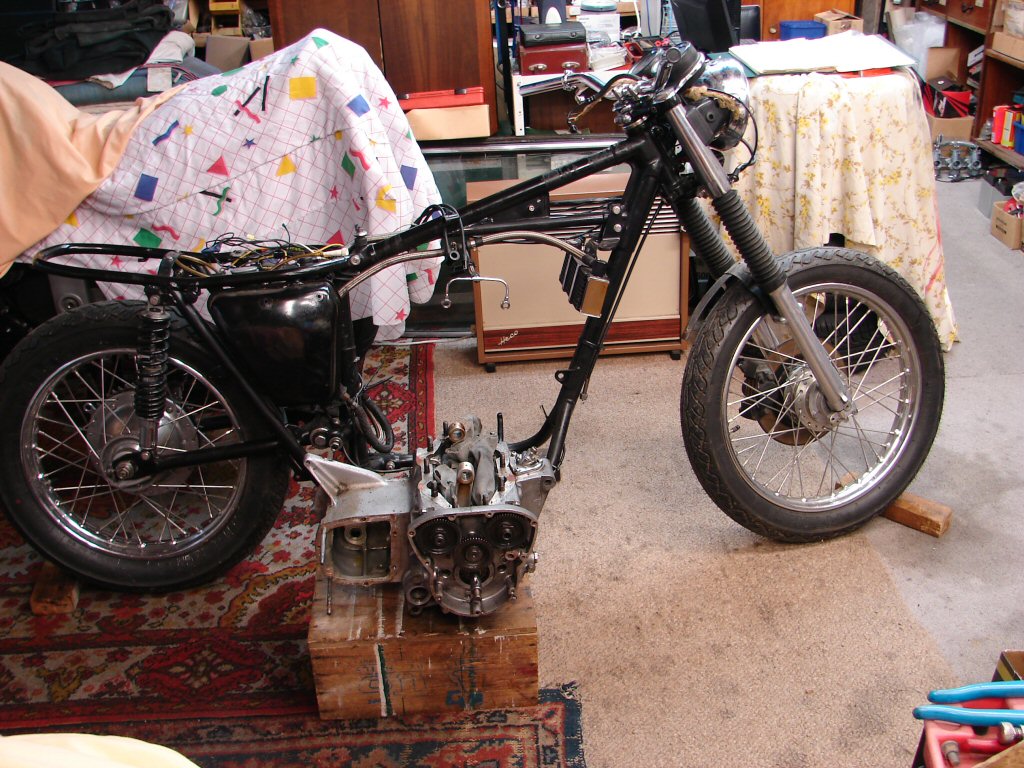
The owner retrieved the frame an hour later, and as I had needed to take another Trident out of the shed to liberate this one, I did the only decent thing and took it for a ride.
As a result of that I found the answer to a mysterious tuning problem on that bike which had puzzled me for some time. Brilliant.
Been a satisfying day.
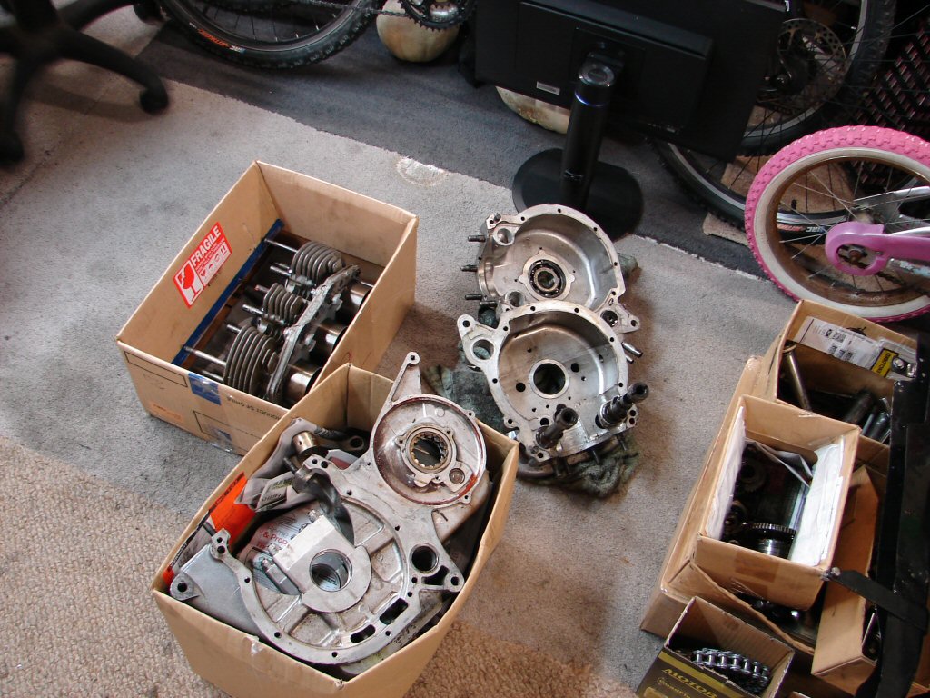
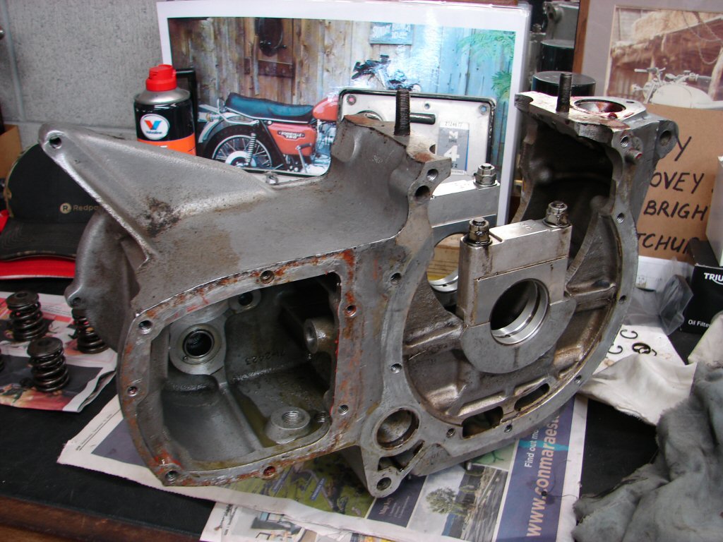
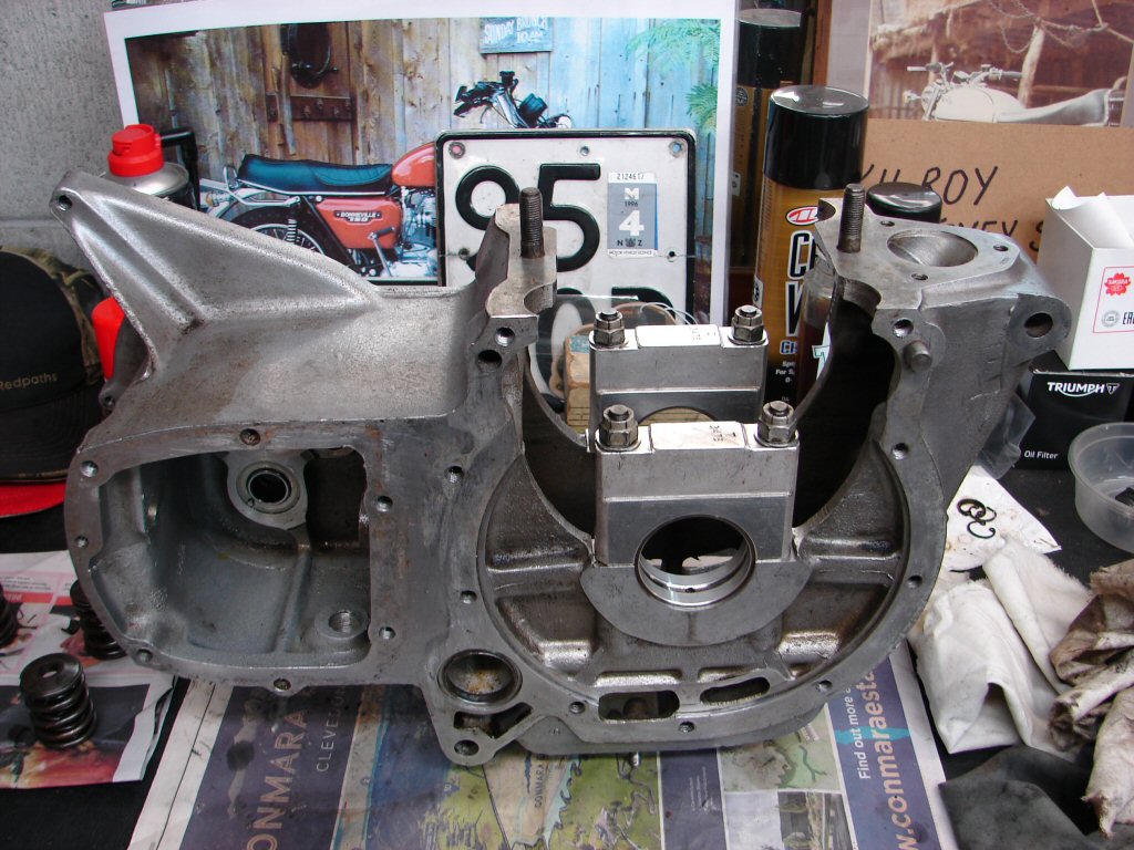
The crankcase came apart, with the anticipated adhesive making getting the two outer case parts away from the centre a long drawn out affair. I finally resorted to a slightly extreme measure which I will not describe here, but suffice to say, no animals were harmed in the process. Better still, all parts will be reusable.
Some cleaning up and the boxed items were carted off to my engine reconditioner for measuring up and prognosis. All the bearing shells were hardly worn, but both they and the crankshaft journals have some surface issues which would hopefully clean up with a polish rather than a grind. It seems that a crankshaft grind to .020" undersize was carried out not many miles ago, but some form of contaminate may have been responsible for the seizure, although over a rather long term.
The measuring will reveal all.
The cylinder head will now be dismantled to see how it has fared, and numerous things cleaned so they can eventually go together. I was able to leave the camshafts and timing gears in place, but despite turning them over a lot of times the closest I can get to correct timing is one tooth out on both cams. I shall continue for a while, as it takes 94 revolutions for the timing marks to realign to where they were first set, and I cannot be sure that what I have found does not occur in the natural sequence of things.
Apart from that, the waiting begins..
Meanwhile, cleaning, cleaning and more of the same.
Removing ancient gaskets takes an inordinate amount of time, but it is the only way to ensure that the surfaces will meet well enough to be oiltight without excessive coatings of goo.
It is always a mistake to assume that sealants will not find their way to the inside of things.
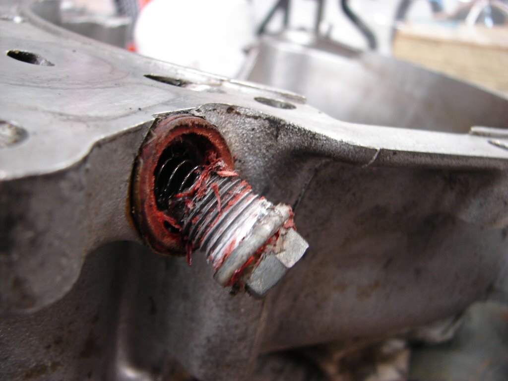
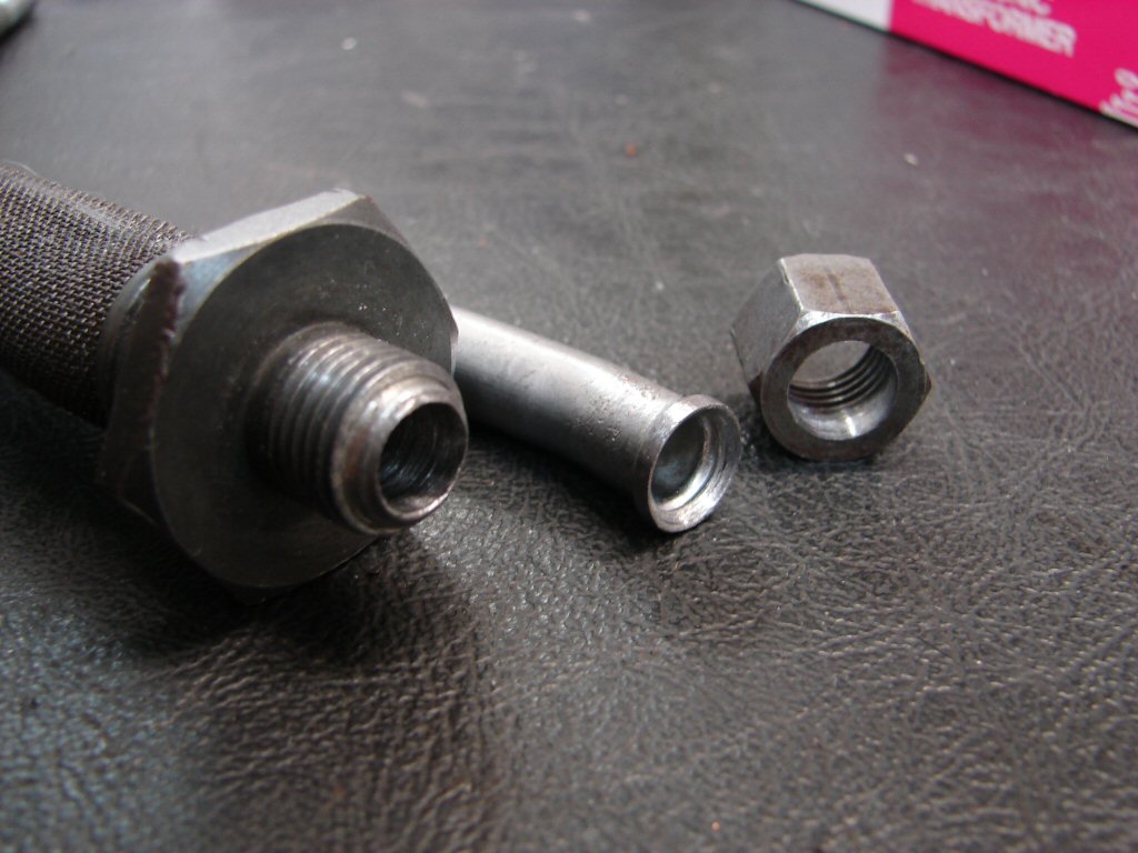
Logically thinking, it seems overkill to have made such a thorough glue and teflon tape job of the anti wet sumping valve seeing that it is hardly under extreme pressure, having a return to the scavenge side of the oil pump via a drilling just above the threaded part.
I guess it was to be sure to be sure...
I am not sure how many revolutions it took, but I finally got the timing marks to line up as I would have them.
As it is possible to choose any of three separate keyways when fitting the cam gear to the camshaft I will still need to check the position of the cam lobes to make sure that all is as it should be. If I knew that this engine had been running since its last intervention I would feel somewhat more confident that what I see here was all that mattered.
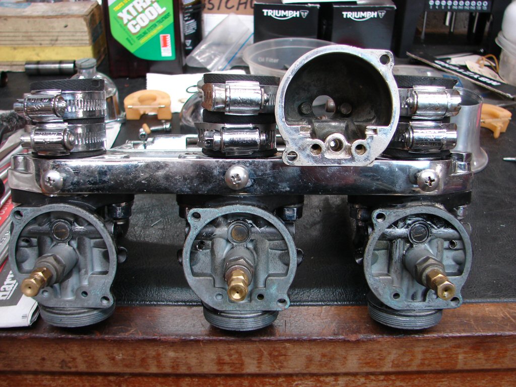
I decided to tackle the carbs next, seeing as how they are a known quantity to mess with and some satisfactory results would be pleasing at this stage.
I always take the float bowls off first, as the float levels usually need tweaking and the jets will likely have suffered a varying degree of fuel residue deposits. Sure enough all three floats came well above the top of the bowl when inverted, so the float jets would need adjusting to solve that. Two main jets were totally blocked with green tar which needed a drill bit to clear. I ran a tiny drill through all the side holes on the needle jets as well, more to check their dimensions than to unblock. All good.
Unfortunately the float jets were another story, as the float bowls have been chromed and in the process the float jets have become chrome plated to the float bowls. They refused to budge.
I figured that there was no other option than that they had to be convinced to play ball, so I tried the boiling water option as first recourse. It took a lot of water but finally the jet responded to a serious thump, and moved about 1/8" of an inch. That was just fine, as tapping it back to where it needed to be was now a normal procedure. Another two jugs of boiling water and all were free, and behaved themselves on the way back to where they needed to be to get us a mm of bowl showing on the far side. The float needles are original nylon type which I am much in favour of, and as they allow the best fuel flow of all types they are certainly desirable on a race engine.
Next job was to clear all the pilot jets and airways, then to check that my CO contact cleaner spray issued forth from all the correct places when injected from either sides of the captive idle jet.
The slides and needles were in good shape and their numbers were as a T150 would most like them to be. The needles were also on the centre notch so no need for total dismantling. The ticklers were the original ridiculously short jobs, so they got replaced by the extended versions which make starting actually possible, let alone with gloved hands. A few O rings and drain plug washers and they all went back together in their grand black and chrome colour scheme.

Final job was to synch the slides by dropping ball bearings through them. It can be a lengthy process, but I fluked it exactly on the second pass. I had to try it several times to make sure it was actually spot on, but it was. Probably the best result I have ever gotten and in the shortest time.
I think the tide is turning.
But then again..
Decided to strip the clutch assembly during the absence of machined bits reappearing as yet. After carefully flattening the locking tabs so that they may do another tour of duty, I found that was impossible to move any single one of the 12 small headed bolts which hold the cover plate on. Not one socket nor ring spanner in my collection fits neatly to the tiny bolt heads, but I have never had trouble undoing them in the past for several reasons. Firstly, they are 'small', therefore should never be tightened to great extremes, and of course they do not need to be as there are locking tabs fitted.
The nature of a locking tab means that it needs be quite malleable, so that the tabs do not simply break off on the first bending. Thus, if a bolt were overly tightened down on one, it would leave a visible scour on the surface. Such marks are not present, leaving only one conclusion. The bolts have been loctited in. Even crushing the flats of a bolt head in an engineers vice does not provide enough grip to move it in the slightest.
I have decided that there are only two options now available. Either the clutch goes back in exactly as it came out, or it goes elsewhere to be stripped. I do not think it will be possible to strip it without destroying a good number of the bolts - even if one can find a 7.5mm socket - and I believe that these are high tensile bolts, so drilling out broken threads would be a difficult process. I shall sidestep the issue.
Yay.
Glen phoned with the lowdown on the engine parts. Conrods and crank are ok although the crank will need a polish. Seems there was some agent that had stuck the whole plot together. The bearings are good except the timing side main roller which has lost a roller, so that gets replaced. The bores are worn but as a race engine a set of rings would have it performing well enough. Unfortunately it turns out that the bores are +010" and there are no rings available anywhere, so we are going to need a rebore to +020" which is now the smallest oversize. Shame but there you go.
Glen spotted that the cylinder liners have dropped in the block, so it will need skimming, and as I had feared, one of the pillar bolts has stripped its thread. As per usual it is one of the front centre threads, so we will fit two oversize pillar bolts, and as per my usual request, the taper at the bottom of the bore will be increased slightly to aid fitting the pistons and rings into the bore on reassembly.
Glen had pulled all the valve guides and will smooth the ports while they are out. I had supplied a set of new harder guides which were part of a one-off order from Kibblewhite, but one of the old guides was +030" so he will need to make a replacement. The engine must have run for some miles with a loose guide and slogged out somewhere back in time. A new set of valves will go in and that will complete the top end work. Only other job will be to fit the new larger engine oil feed pipe which requires honing to get the correct press fit tolerance.
Majority of required parts have been ordered and are already on their way, so I have begun the big clean up in preparation.
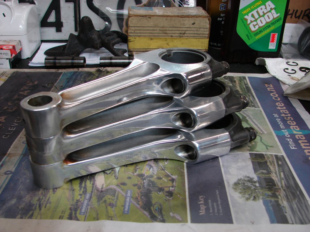
Today I started with the conrods.
While they are hardly going to be on display I always polish the rods during the cleaning process to destress them. Any scratches may lead to cracks given half a chance, and we can assume that this engine is going to experience its fair share of stress.
I have no idea why someone has carved a bit of alloy off the base of the centre rod, and hope it was a balancing measure. Perhaps the centre rod was replaced somewhere in history - you just never know what these machines have been up to in their past.
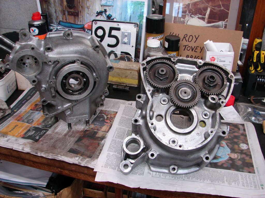
Next daunting task would be to clean the centre crankcase, being the starting point for the coming build. It takes hours to get these bits to the standard I am happy with, most of which is the laborious job of scraping all the old bits of gasket and adhesives off, and as mentioned previously, there is a lot of cement and silicone all over the place.
When I find a lot of sealant on joint surfaces, especially where a gasket is used, I can only assume that it means the previous builder was not sure it was going to be oiltight. I prefer to put in the time it takes to get all the mating surfaces to the condition where I know the gasket will do its job properly as is. I think that the true measure of a good engine build is when it is a delight to dismantle it, should the need ever arise.
The first stage is the 'mechanical" clean, so scraping, wire brushing, using pointy things to dig silicone out of blind threads, running die nuts over all the studs and taps into every threaded hole. I found a sizeable coating of sealant inside the scavenge drilling above the pickup, so was glad to have that risk factor gone.
Here we are at the end of the mechanical clean. The next stage is the "chemical" clean, which involves flushing out all the blind threads, the oil galleries, and generally flushing the crankcase interior to get rid of anything I disturbed in the process.
After giving all the threaded holes a quick touch of a 1/2" drill by hand to chamfer any protruding swarf the chemical warfare took place.
Pleasingly the internal oilways were pretty good to begin with, although the front plugging screws were liberally glued in. I have never had a leak from this area without using sealant, and as I like to attach an oil pressure gauge to whichever side takes my fancy, it is nice not to have to clean anything once oil is present.
I am now happy enough for the assembly to begin when we have a polished and oilway cleaned crankshaft.
I have had two major players during my history with engine building who gave me good advice. The first was a long term flatmate and engine reconditioner to whom cleanliness was the holy grail, and he recently paid compliment to a crankcase he saw on my bench, so I figure I passed the test.
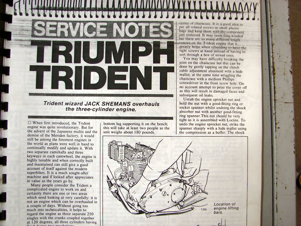
The second, and much more specific to these engines, is a wonderfully detailed step by step engine rebuild by Jack Shemans in a collection of magazine articles I was once given - all concerning triples. I noted early in the piece that when Jack Shemans says that you fit a particular gasket dry - you do just that. There will be a wealth of seasoned logic behind the statement - which I have just experienced in reverse.
Today the majority of the engine parts returned from the machinist so I am happily involved in the beginning of a build for a change, which is very timely as I am about to begin another total strip of another T150 and I would rather not risk getting any parts mixed up.
I had asked Glen to extract the timing end main bearing while he was cleaning up the crank, and when he did he found that the cage was broken and one roller was missing. He couldn't find it in the carton I had delivered the crank in, so it appears to have already been missing. The outer race of that bearing was well worn so it was already slated for replacement, but it is a mystery indeed. New oil feed pipe fitted and as I expected, the crank oilways were totally bunged up with centrifuged carbon which had to be drilled out.
It will be lighter.!
First job was to trial fit the main bearing shells to ensure they were all happy, which they are. The big ends however were not so fortunate. Now that the crank journals have been polished they are visibly worn enough that they will not be joining the plot. The corrosion removed from the crank was seemingly what had caused the seizure of all three conrods, so that explains a number of things.
A new set of shells have been ordered so hopefully play can resume with only a few days delay. Meanwhile I have switched my attention to gapping rings and fitting them to the pistons. The supplied oil rings are cast but with a rather strong internal expander, to the tune that I envisage some trouble getting them into the bores. I have fitted clamps and left them sitting in the top of the barrels meantime, in the hope that they become a tad more compliant.
Seems the pony express has failed in its duties, so I took the easiest path and assembled the cylinder head. It has had a few thou skimmed off the head surface, and the valves albeit new are somewhat low in the seats as a result of various past replacements. Two valve guides were grossly oversize, presumably because their predecessors had run loose in the head for a while, so Glen had to machine two replacements.
During the ring gapping procedure a new issue became apparent. The Hepolite cast oil rings with their expander are extremely resistant to being compressed. I had to remove the expander to get them into the bores, which does not bode well for the fiddly job of convincing the piston assemblies to enter the bores while balancing the barrels with the other two hands.
However, like Baldrick, I have a cunning plan...
Many triple engine builders are in the habit of having the centre piston already in the barrel while assembling, as the big end cap can be tightened through the sump, and only two pistons needing to be coaxed into the bores is much easier than three. With these oil ring expanders being so uncompliant I was looking to develop that approach even further.
As the two outer crankcase sections are yet to be fitted, it should be possible to fit both outer conrods to the crankshaft before fitting the outer cases, while leaving the third conrod to be tightened via the sump. The only seeming consideration would be that the studs around the top of the crankcases which retain the barrels would necessitate supporting the barrels to clear them, but with the pistons being so tight in the bores I think the barrels will mostly support themselves and just require steadying. I would also need to have the base gasket held to the base of the cylinders before the conrods were attached.
Worth a crack Nigel..?
The new bearings showed up today so I am almost ready to begin the plan. A bit of thread cleaning first, so all the crankcase captive threads and bolts are ready to go together, as the outer cases will have their sealant applied before mating up, so I will not want any delays if damaged threads show up. The fact that all the bolts have been chrome plated does not assist getting them into the threads, as they are slightly larger than they should be thanks to the extra thickness of the plating. Running a die nut over them all should help.
Glad I did that, some of the bolts were quite nasty, but all sorted and ready to go. I decided to forego one of Stan's tips and glued the base gasket to the barrels so it stays put.

So here we are with the trial fit. The two outer conrods are sitting on their respective journals and after being oiled and tightened the barrels get raised just over 1 inch so the outer case studs pass beneath. I did a trial fit with the right side which still has the timed camshafts in it, and you can see that the camshafts neatly avoid the cylinder liners and the conrods. The left side cover then simply fits over its main bearing and the camshaft journals and the centre conrod will be the final manoeuvre.
I wonder if they ever did this at the factory... lol.
We shall now have a blow-by-blow pictorial account of the assembly process.
With the barrels supported by four sockets from my 3/8" drive socket set which were just the right height the two outer conrods got bolted up and torqued. The T150 workshop manual states 18 ft.lb while the T160 manual states 20 ft.lb, so as the parts are identical, 20 won out.

The right side case then received various helpings of oil on the running surfaces and some alloy silicone sealant after which it bolted up perfectly, with the exception of the missing bolt which despite being the chromed original began to pull the thread despite not yet tightening up. Removing it revealed that it was 1/4" shorter than it should have been and had thus done some damage last time around.
I trialled a much longer bolt and found that we have enough undamaged thread to do the job, but as I do not have a UNC bolt of the correct length I will need to obtain one.
The drive side case was an even simpler affair and was on toute de suite and the barrels engaged with the base studs. You don't push the barrels right down initially as then you cannot get the nuts in the gap.
When left long enough to cure properly the excess silicone which has squeezed out of the joint will peel away in an easy long string.
Barrels tightened down, centre conrod tightened up, sump filter and plate fitted.
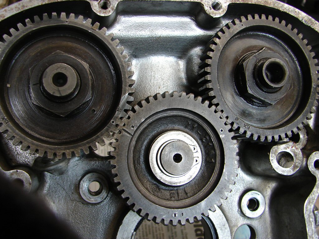
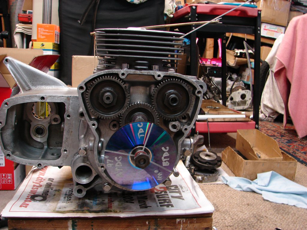
Camshaft timing marks are all aligned here, left piston is at TDC and I am about to fit the crankshaft timing pinion, after which I shall fit my 'patented' timing disc in order to check the cam timing accuracy.
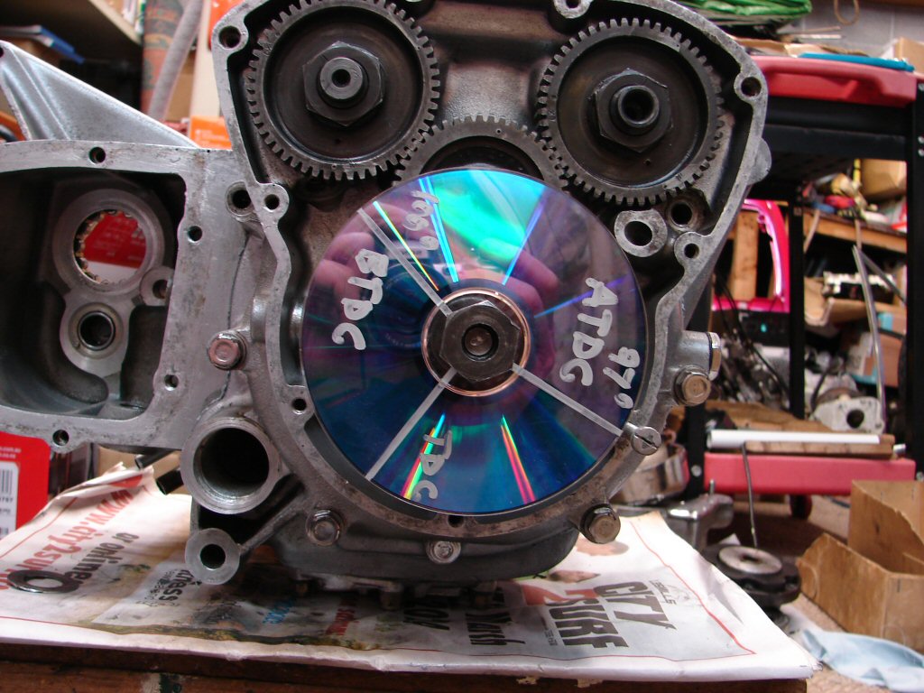
Using my tried and true cam centre lobe timing method I first find true TDC using the wooden rule you can see held by a rubber band across the piston crown. This elevates to a maximum height which is of no great interest, but then pauses before beginning to descend. Finding the halfway position between rising and falling is the art, and determines where I then position the DVD to align 'TDC' with my 'pointer' - being the slot in the screw head.
Next step is to sit the steel rule between the cylinder fins and resting on the cam follower then repeat the same process while turning the crankshaft backwards, although the 'null' point is of longer duration because of the shape of the camshaft lobes.
Very pleased to find the exhaust cam is spot on.
>
The steel rule now moves to the inlet cam follower and the crankshaft gets rotated forwards until the maximum lift is obtained, a bit of rocking to and fro to determine the centre point and there we have it.
The inlet cam is fractionally advanced to a degree I could not have found if I wanted it, but would have chosen if I could. This slight advance should boost low end torque slightly and is of good advantage under acceleration out of corners. The inlet cam gear has two timing marks and this is using the higher performance option, where the later T160 used the lesser one in order to please the US emission control laws. Correcting the timing of T160 cams was where I developed this method.
One very pleasing observation. When doing this fiddly job I fit the primary front sprocket which I wrap a rag around and manipulate it by hand. With the oil rings being such a struggle I was thinking this was going to prove rather difficult, but to my delight it was no more so than any other I have done. That relieves any concern I had that those rings were too tight in the bore.
From this point of assembly it will now be best that the engine is re-installed in its frame, as it is then held secure enough to wield larger spanners with enthusiasm.
Today I cleaned up the tacho drive and fitted it as the frame downtube makes access a bit difficult once the engine is mounted.
I also bought and fitted the missing crankcase bolt and began the laborious cleanup of pillar studs, head bolts, pushrod tubes, rocker box bolts and screws and the clutch bits.
I fitted the pillar studs with all their internal threads cleaned out, but left the four outer long studs out as they make fitting the head a nuisance.
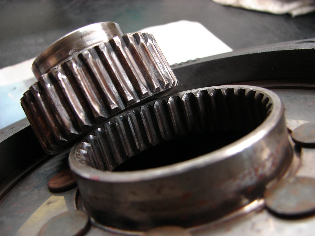
Unfortunately when cleaning the clutch hub I found that the teeth of the spline were worn to the point that it would be foolish not to fit a new one. That made me take a better look at the spline in the clutch plate, only to find it was kinda the same. When fitted together there is a lot of play between the two, and the sliding action when loaded is rough enough that it would make gear changing a challenge rather than a joy, so new ones will be ordered right away.
I had been hoping that I would not need to disturb the clutch assembly as I could not get it apart, but now it has to I shall take it to Glen for advice. I do not wish to snap any bolts off so some heat will be needed, but mostly I need a 7.5mm socket. Maybe he has one...
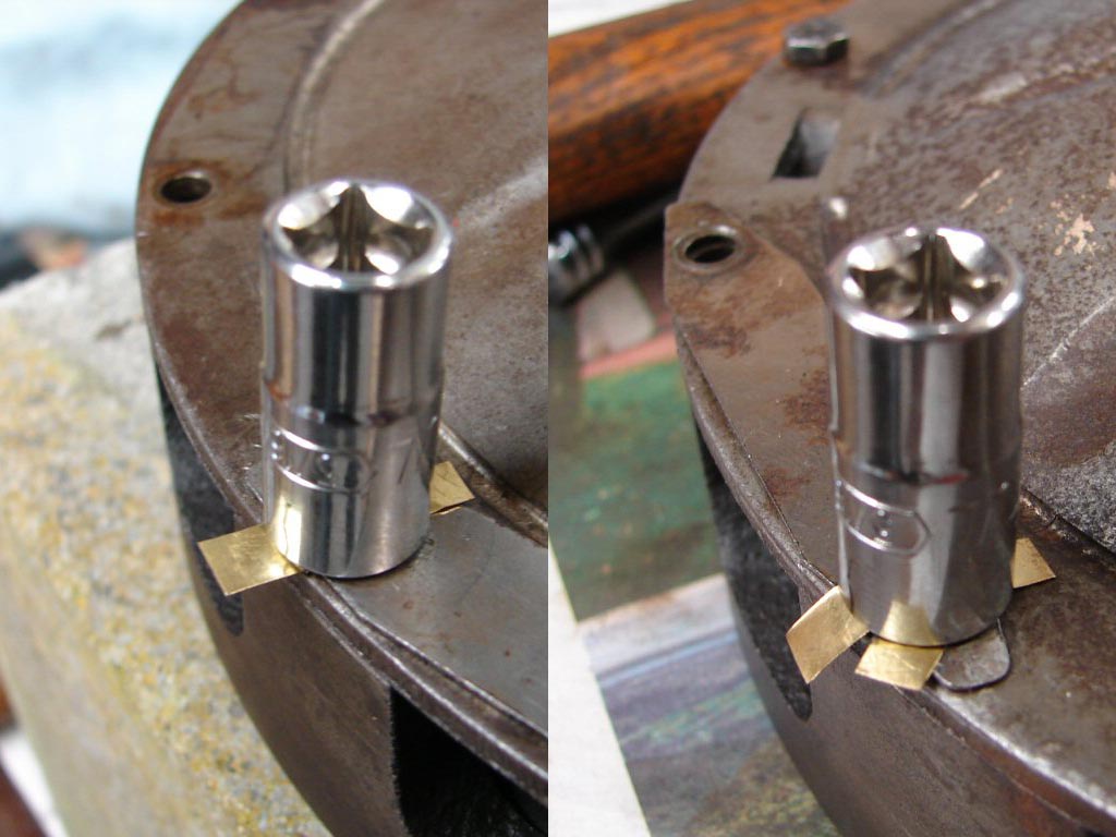
No, he did not have one and nor did a tool place I then visited, but I did buy a new 1/4" drive six sided socket of 5/16" which is the nearest size up. Then I went home and cut a strip of brass shim and pressed the new socket over the first bolt head. It was still very tight, so I placed the clutch on a concrete block and gave it a butane enema. That worked.
I continued the process while testing each bolt before heating and managed to crack half of them cold. The final bolt was the worst so I added a second piece of shim and it surrendered.
Win.
The clutch proved to have a liberal amount of oil within, and I am guessing that the sintered iron clutch plate it had may have managed to keep working despite that fact.
Other than that and requiring a whole lot of cleaning it was in good shape and still had its red spot spring which is the lightest to operate and handles all the bike can throw at it.
New stock clutch plate and hub are on their way which I feel most reassured about as many parts are in short supply these days.
In the process of cleaning up associated parts I found the cush drive retaining nut. I guess we can see why there was so much oil in the clutch then. Common mistake if you don't have the manuals on hand.
I find it totally necessary but rather tedious to have to clean all the oily bits and make sure their threads are not going to put up a fight on the way back together, but it certainly pays dividends when you are actually assembling the engine and there are no unexpected surprises.
Happily there were few surprises as the engine went back into its frame, which had come back with a paddock stand that makes life easier for me than working on the sidestand. The alternator was the first addition, and within minutes one of the crimped bullet connectors fell off the wiring. Quite fortunate actually, as I would never have gotten two of them through the small path that the wiring follows.
This was followed by fitting the gearbox high gear and the new front sprocket, during which the mainshaft oil seal got replaced as well. I decided to count the number of teeth on the rear sprocket before refitting the rear chain and found we have 50t versus 18t on the gearbox. The manual states the original as being 53t, so we have options to gear down a bit if needed. Will depend on the track, but the current ratio should suit the local track quite well.
I also cleaned the wiring out of the way before fitting the engine, and that will be dealt to later with only a very minimalistic approach required. Unless there is a change to endurance racing needing headlights of course...
The final move today was to refit all the gears and bits that move them inside the gearbox. There is a fair bit of cleaning needed before the outer case can be fitted so I will be concentrating on that next.
If anything should foil that plan I have a nice clean clutch to fit around its newly arrived plate and hub, so no shortage of things to attend to.
So thats nice..
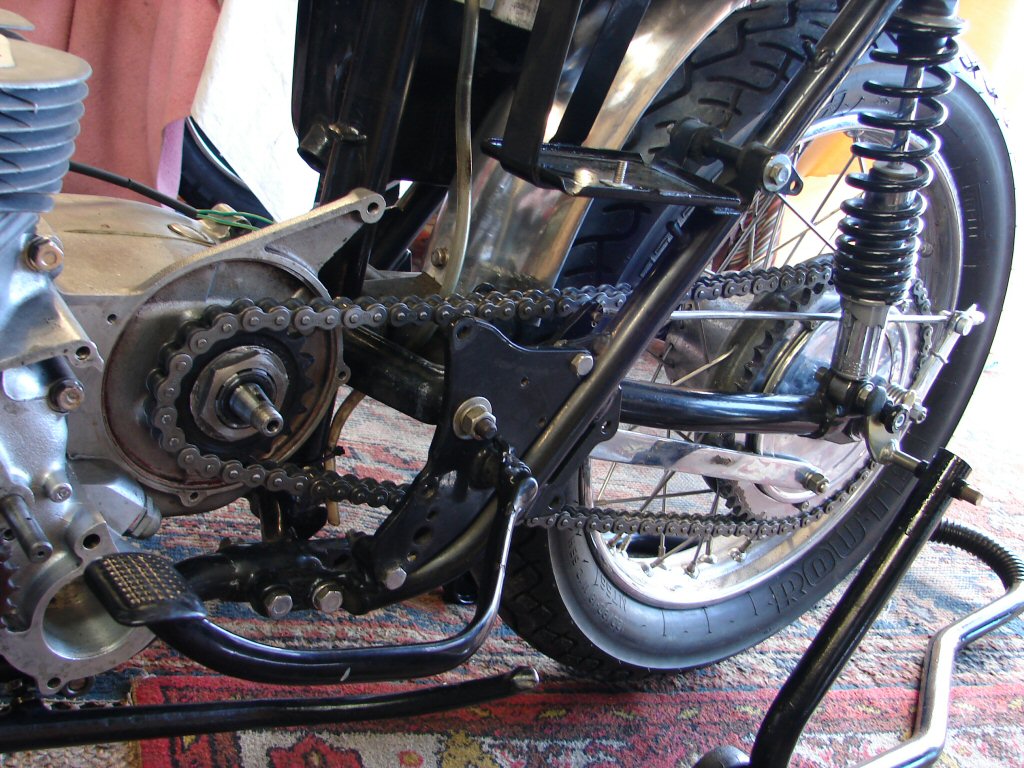
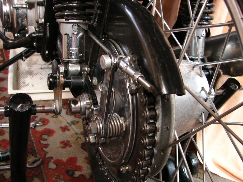
I needed a chain fitted about now, so it would be possible to lock the transmission up, with the help of the rear brake, in order to tighten various nuts before any more covers went back on.
There was a real heavy duty chain that came with the bike, but its larger dimensions caused it to interact badly with the screws behind the sprocket that hold the seal retaining plate. These screws were obviously not the originals as they had quite large rounded heads, so I filed them down to half their head height but there was still a problem. I was also concerned that this monster chain was going to be a massive rotational mass when in use, so considering the two problems we bought a standard 530 chain and that solved the clearance problems. Having done a fair bit of thrashing back in the day I think the standard chain will cope perfectly well. So here it is, having been shortened from 110 to 106 links to suit the cause.
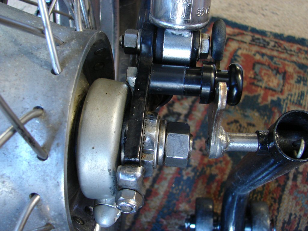
Unfortunately that was not the end of the resistance. There are mounts for a paddock stand bolted through the swingarm, and with the chain adjusters backed off to suit the new chain there was another interference problem between the inner end of the bolt and the speedo drive. While there will likely not be a speedo, the drive needs to stay put for its dimensional contribution.
I hacksawed a 1/4" off the bolt, which now allowed the nut to stick its oar in. Off it came again and I filed a major chamfer on one flat, which finally allowed everyone to get along famously. Not a great deal of the progress I had intended to make, but such is life when you are trying to assemble bits that were not previously in service on this machine.
Now we had a working brake The kickstart ratchet nut got tightened and its locking tab applied. The sprocket got the same deal, which in turn allowed the fitting of the clutch housing with its new seal. A bit of loctite is used on the retaining nut for the clutch hub, even though it is both on a keyway and a tapered shaft. To be sure to be sure.
It was also the correct time to fit the cleaned up oil pump, so that as soon as the oil lines are restored I will be able to pump up some oil pressure by hand to lube all the bearings before any action is undertaken.
For a change of pace I removed the rest of the wiring and the rectifier which got treated to a coat of paint, being sunny and all. The coils got a clean up and I began inventing a method of connecting The various killswitches on the 'bars. Those and the zener diode and a decent earth would be the only wires that needed to head north.
I figure that an oil light would be a waste of time as it would unlikely be seen in time to avoid the big lunch. However, and as we have the original oil pressure switch, I might fit a relay which controls power to the ignition, so any extreme loss of oil pressure will turn the engine off. Just a loose oil line could cause such an event, so best save the donk.
Final move today was to see why the twistgrip was semi seized up. I assumed that it was only fitted to the bars before the frame came back for its engine, and it was not getting along with the bar end protector that was hard up against its rubber grip.
When I pulled it off it was apparent that these two had been in a relationship for quite a while, and it had not gone well..
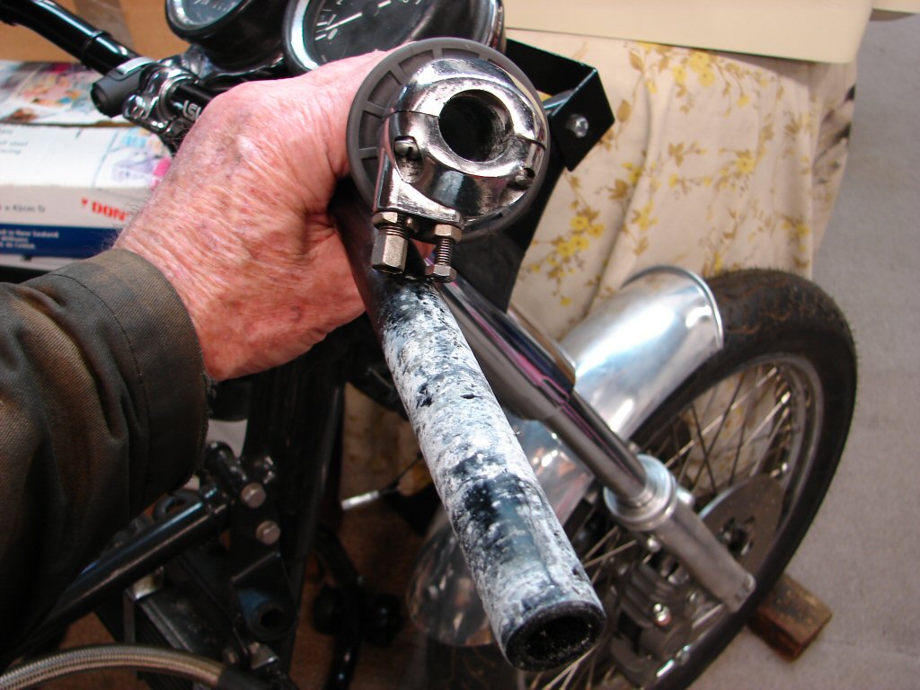
With the rubber cleared and some sanding and wire brushing we now had a clean acting twistgrip - important consideration for a race bike.
Then there was the final final move for today. I decided to test fit the gearbox outer cover to make sure the kickstart and gearlever engaged properly as well as try a pair of domed nuts to replace one stripped one and a self-locking which had been there before.
This is where a kickstart lever parks itself when the cotter pin has been fitted the wrong way round. When fitted forwards the cotter rotates the lever to where it is almost vertical, thus giving the budding kick starter some useful extra arc of operation with which starting is a more likely result.
Whacko.
I just know it is going to put up a fight.
Well - it did, but a bit of heat changed its mind, so that was pleasing. It was not in good shape, not from the removal but its former life. I had a new one on hand but it seemed I could recover it and it pleases me to do so, so I decided to give it a go.
First I straightened the threaded part as that was the make-or-break stage, and as it survived I recut the thread then filed the flat side enough that it would slide reasonably smoothly into the lever.
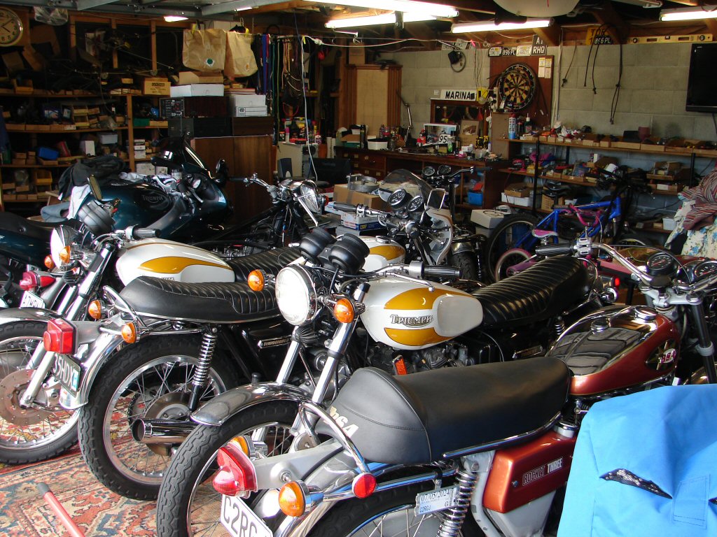
Meanwhile the average xmas is taking place in my shed. Whenever there is a deadline I get dead bikes seemingly from nowhere. No less than 7 triples in here right now.
That meant a fair bit of today was spent repairing others, as it was necessary in order to reclaim some space.
Despite that I got the gearbox cover refitted along with the kickstart lever and the engine mounting plate. I had also found that the new copper head gasket was pretty hit and miss with the head stud holes, mostly miss, and even a couple of the oil drain dowel holes were partially obscured. That entailed some time with a dremel easing the holes until they just allowed the gasket to slide into place. As it will be fitted with a fresh coat of copper spray it is not wise for it to be a fight.
As if that was not enough hassle, the head would not fit over the pillar studs without a struggle, and I remember having had quite a fight when I took it off. I measured the drillings that the pillar studs fit into and found that there were two different sizes, the larger being a shade under 1/2", so I drilled the others to the same size, and now it fits with slight effort. I trial fitted it and can see that it will go the final 1/2" with a few rubber hammer thumps, so I shall leave that until it is a live operation.
From memory the piece of broken fin was glued in place originally, but it went missing during the machining processes. I'm guessing it will be in the bottom of Glen's cleaning bath..
On t'other side I fitted the clutch assembly in place having locked the tab washers, greased the splines and repaired the outer end of the pullrod. I also loosely fitted the oil pump drive gear so that oil will be able to get pumped around as soon as the final mods to the oil delivery are complete.
That would have been easy if there were any T160 oil tank filters available but there are not, probably because many people have uprated the tank to oil pump line size as was brought in by the factory during early T160 assembly. Now I shall have to drill out the original smaller bore tank filter and convince the larger pipe to fit within the smaller union nut.
Also the cylinder head fitting will need to be complete as oil will spew forth from the rocker box oil feeds.
Half of every rebuild is all the stuff that nobody thinks about, because you only have to attend to it as the build presents each challenge.
After obligatory festivities I got back in the groove today. First step was to fit the oil drain dowels into the head. Some were quite a loose fit and it seems that the holes may have been opened up a bit, possibly because they can be a bit ornery to persuade into the barrels. I used a smear of silicone to ensure that the oil has to flow through rather than down the outside. This now means a quarantine period for curing before fitting the head.
That meant I had time to refit inlet stubs along with a few missing gaskets revealed when they came off. I often find such things when the inlets are removed, so I make a point of it, as even a small air leak here can make accurate tuning almost impossible to achieve.
Next thing was to organise the larger oil tank outlet, first by drilling the original nut to clear the now 3/8" exit pipe, then hand filing the flared edge of the pipe union until it fitted within the nut. It is possible but only just, and the sealing area between the pipe and the filter is minimal.
The bore in the filter has to be opened to 5/16" which is as large as the inside dia of the pipe which has a kink in it to allow the flexible line to co-exist. I used 3 drill bits in steps to make it an easier affair - which it was.
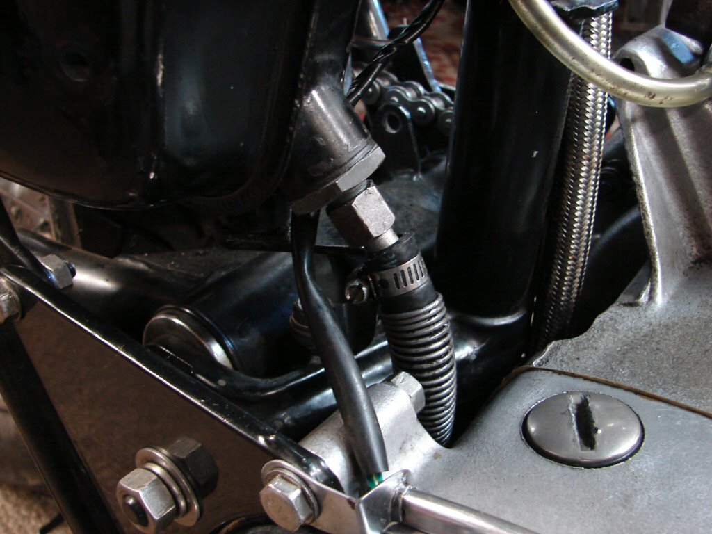
I managed to fit the original protection spring on the new larger flexible line and engaged in the usual fiddle which is the hallmark of refitting the oil lines to the crankcase pipes. Even though the jubilee clips tighten as they should, I have seen a line migrate off one of these crankcase pipes, so I take the simple step of cable tying the two lines together as a small insurance policy. It is a cure I once had to employ on a dishwasher whose drain hose kept migrating off a spigot despite both silicone and a clip, due to the extremely hot operating temp it was handling. Same applies here.
This bike has the enormous stainless braided lines fitted between the crancase, oil cooler and oil tank return, and I don't rate the jubilee clip as having the ability to retain those very well either, so the cable tie is for the benefit of both. I would not have such lines on my machines for this reason, but also because they have a habit of lacerating your fingers with various loose stainless spikes. All that aside, the fitting to the tank behaved itself, and I have crossed fingers that it will be leak free.
The cylinder head refitting was preceded by a clean up of the rocker boxes, as they would need to be dummy fitted in order to gauge the amount of compression available for the pushrod tube seals. Too little or too much can both lead to annoying oil leaks. The rule of thumb is a minimum of .030" for the pair, and I make sure that I have a little more than that, by adding fibre washers beneath the lower seal cups.
The head gasket was given a coating of copper gasket spray both sides before being dropped on, then the head went on and some tension was applied to the four outer studs. Both rocker boxes were then fitted with all their head bolts and everything got moderately tightened in the correct sequence. This is just to maintain even tension on the head versus barrel surface, after which each rocker box is removed in turn, trial fitted with aluminium gasket and pushrod tubes but no pushrods. With necessary spacing achieved the pushrods are fitted, rocker box gasket is given a light smear of silicone sealant, and the rocker box fitted completely. The only measure not applied is a smear of silicone on each of the cap screws along the leading edges of the rocker boxes. These will be cleaned up after the first run and head retighten and the sealant applied at that stage, as things tend to move a little with the first heating and cooling.
Using a socket on the alternator rotor nut I then was able to rotate the engine while setting the valve clearances and fitting the covers. Much old blue glue got removed in the process, as I fit the covers dry. If they leak I will resort to some sealant, but only if I cannot remedy the actual cause of the leak, which is often due to the covers having warped due to overtightening.
Next was to refit the rocker box oil feed, but I was not happy with things as they had arrived. The physical size of the braided lines is a major factor, and so they had been crossed to opposite sides of the main frame tube and thus opposite sides of the oil cooler, but this had put the rocker feed tee pipe in an odd position to mate up to the feed itself, as well as creating a big disturbance at the rear of the fuel tank where the two lines crossed over each other, so I ripped the lot off and put them back on the sides they should have once been. This got rid of one small piece of braided line to the oil feed as a longer line was needed and I just used ordinary hose. Now it all lines up and everyone is happy. Mostly me.
Now I can look at getting some oil in the system.
Half a litre in the tank and cranking the pump drive gear for a few seconds and we had oil running out of the oil filter cavity. It looked nice and clean so I fitted a new filter and buttoned it up.
About 30 seconds later we had some serious oil pressure and I could hear oil escaping from the crank bearings. I had put the return line into a container and soon there was oil arriving, also clean, so the line went back on the oil tank.
That led to an hour cleaning the inner primary cover which had a well stuck skin of gasket everywhere, and lots of silicone at the bottom of every captive thread. While it is mind numbing work there is no point in assembling wet areas without spotless surfaces, as the result is predictable.
Finally happy with the condition and with a new oil seal for the cush drive and O ring for the oil pump it went back together. I had to make a replacement for the missing 4¼" bolt by cutting ¼" off a 4½" bolt then cutting the thread a bit further up so it would go fully home. Oil pump gears now went on in final fit so the lock tab is now applied.
The primary chain and sprockets were now retrieved from their hiding place and another cleaning process began. I had acquired a set of cush drive rubbers as I had noticed that the cush drive cover locking tabs were all broken and had obviously seen some action. Regardless of whether they might need replacing or not you simply have to look at everything, as the one thing you do not investigate will invariably bite your nether regions.
Considering how many parts of this engine have required remedial attention I was not prepared for what I would find in the cush drive, but it was a real big surprise.
The rubbers look to have hardly seen any serious mileage at all. I am so pleased to have found something that exceeded my expectations - cool stuff.
A bit of cleaning and a new set of lock tabs and it was good to go. The crankshaft sprocket tab washer was convinced to sit flat against the sprocket and the cush drive retaining nut was treated to a new oil seal facing in the correct direction. I use a piece of insulation tape over the pullrod thread to protect the oil seal, and a smear of loctite on the clutch cover thread is an absolute must. If that nut works itself loose the spline wears at an alarming rate. As per usual practice an O ring is fitted at the base of the spline before assembly, as while not being a factory part it prevents oil from creeping along the spline and into the clutch cavity. As it happens the crankcase O ring for the T160 gearchange cross shaft (60-4419) is the right size.
Having reconnected the rear brake lever and placed the bike in top gear I was able to crank a fair torque on both the critical nuts on the primary sprockets, while also doing the alternator rotor nut which will now allow refitting of the timing cover.
Trial fitting timing cover and checking the new oil seal position.
Primary chain fitting complete, locking washers applied and loctite already curing. One of the main fiddles here was the possibly unnecessary oiling hose which delivers oil from above the rear sprocket to the lower run of the chain. While its contribution may be of questionable value it serves the purpose of locating the small gasket which seals the base of the two outer cover screws which are located in the centre of the cover.
The primary chain adjuster screw had presumably lost its fibre 'button' which supports the tensioner blade, so instead a blob of solder has been applied to the adjuster end and the whole thing fitted upside down. While not an elegant solution it actually does the job well enough to leave it that way. I also note that the part is not available of late.
Today saw the timing cover get its final fit, plus the Trispark installed and timed. I have yet to run its wiring loom back to the underseat coil repository as I need to fit a small rubber sleeve to the loom at its entry point to prevent any moisture getting aboard.
There is also a need to replace the 3 tiny screws that retain the patent plate, as there are currently 3 different screws in use, none of which look like they belong there. The plate will not be finally fitted until the engine is run and the timing checked with a strobe, so it is not a holdup.
Because the Trispark is now in place I will begin the task of making up all the electrics and a wiring loom, albeit without all the frippery of lights, indicators, horn etc. Mostly charging, ignition and earthing, with a robust fuseholder as the originals were often a source of intermittent problems.
Their connections were prone to melting..!
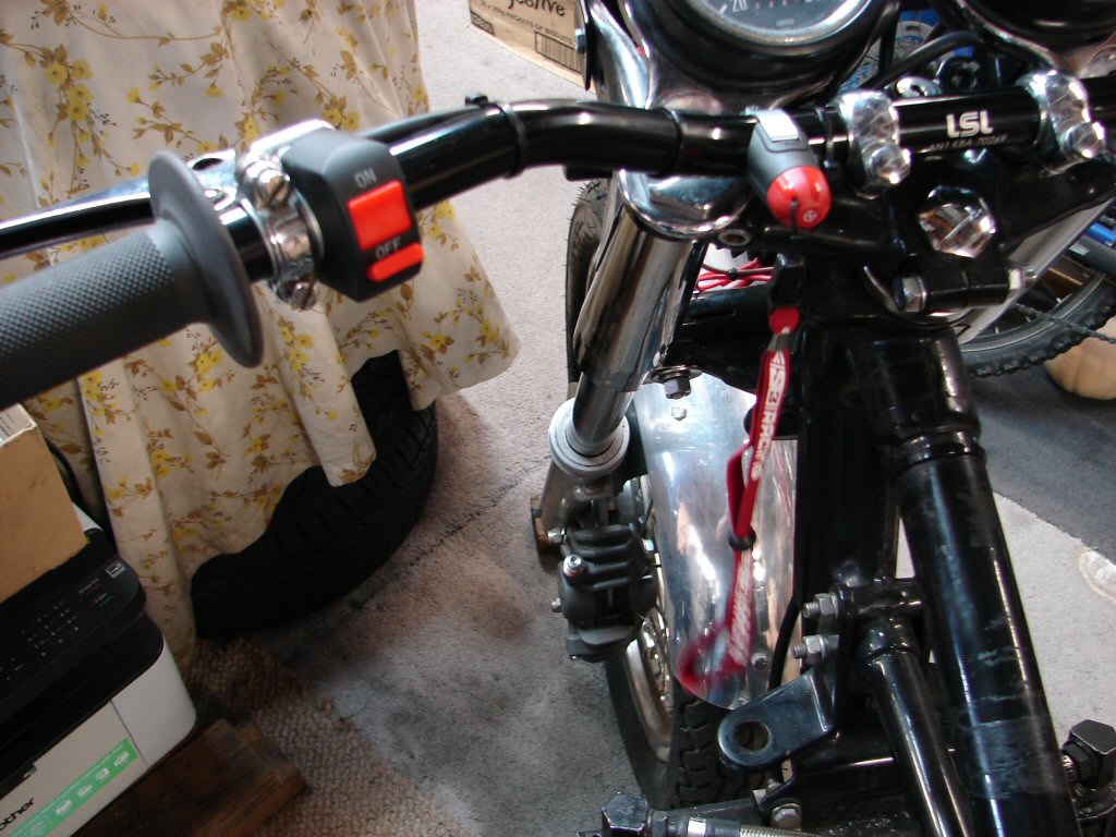
As per usual practice I fit an ignition relay, as it provides the best voltage to the ignition unit and electronics can be picky. Regulations demand that the bike has a "dead man switch", so that the engine turns off if the rider parts company with the bike. The switch is already in place on the 'bars along with an on/off switch, and is activated by a magnet attached to a lanyard presumably worn around the rider's wrist. I think I would be attaching it to my jacket, rather than have the bike shut down while giving another competitor the finger.
I checked the functionality of the two switches, only to find that the dead man switch is off when the rider is on, and vice versa. This means a second relay is needed, one which I had already planned to fit. Because an oil light is hardly going to make itself known if oil pressure vanishes in the heat of battle I had decided to use the oil pressure light switch to operate the second relay should the worst case happen, and this relay having a normally closed contact will disable the ignition relay and kill the engine. Now I find that the dead man switch has its functions reversed I will simply allow both switches to be "earthing" so either will operate the killswitch relay. The only penalty clause is that the ignition will not turn on until the engine has enough initial oil pressure to operate the oil pressure switch, which I intend shall only take 1 kick to achieve.
So thats nice.
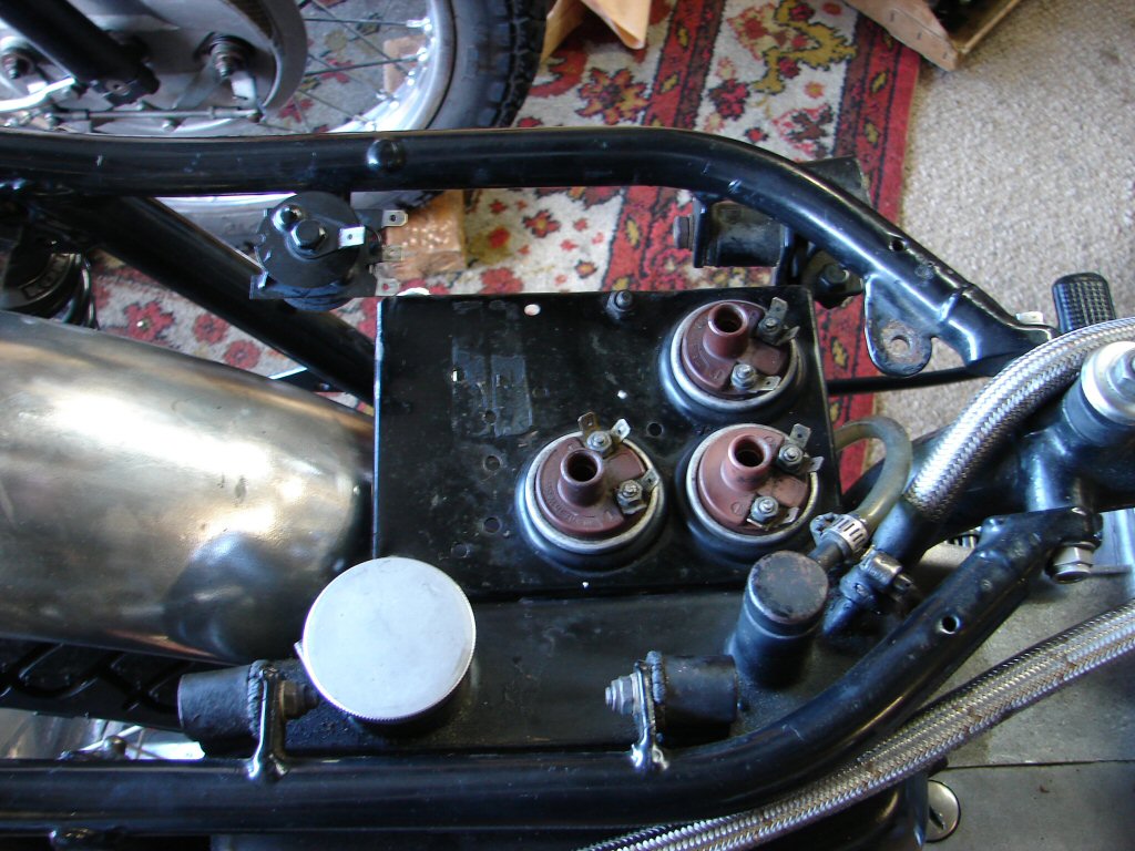
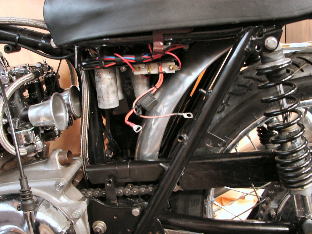
Relays in place and wiring soon to be forthcoming. There is a ballast resistor lurking beneath the coil platform, as the bike was fitted with 6 volt coils, and it is a much cheaper option to use the resistor than buy new 12 volt coils.
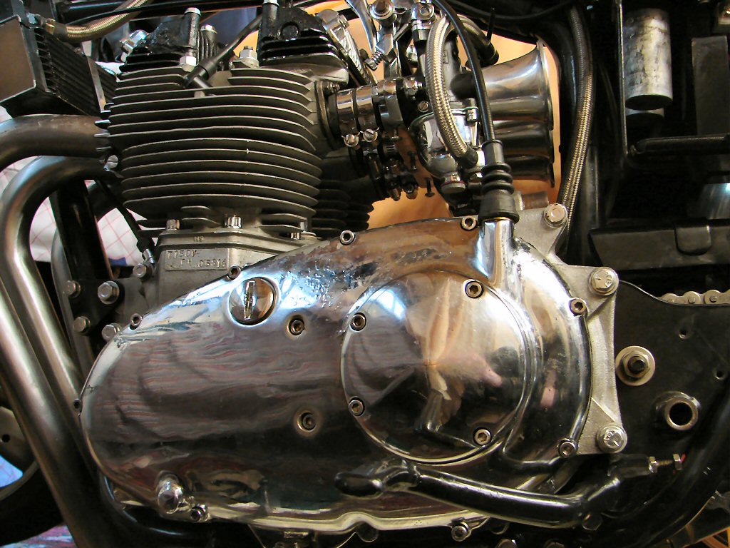
Back to cases. Time to clean up the primary outer cover, which had also suffered from tarry gasket residue which has to be scraped off completely if we want a leak-free primary. The occasional screwdriver scar where such a tool has been hammered into the joint to get the cover off in the past has left a gouge or two, but hopefully some silicone sealant will fill the gap. Literally.
There was another problem in that I had been unsuccessful releasing the clutch cable from the operating lever, so had taken the cover off with the cable still in it. I had to work with the cover held close to the vice so I could spread the retainer enough to make it let go, which also required spreading the two arms which hold that. A lot of work for what is usually a few seconds job, but it was really tight.
After that I repaired the operating lever and fitted the new pullrod bearing.
The chrome plating is leaving town in small flakes which invariably dig themselves into any passing finger, and it seems that this plating process never manages a long life, as they all seem to fail in the fairly short term. However there is a real problem created by the extra thickness of threads and drillings which make life difficult. In this case it had caused something else altogether, and I am very surprised I did not notice it sooner. Mainly because I was not looking there yet.
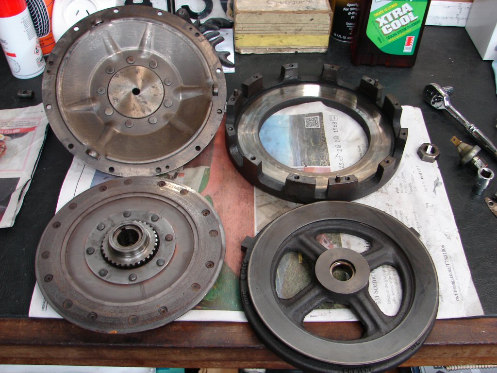
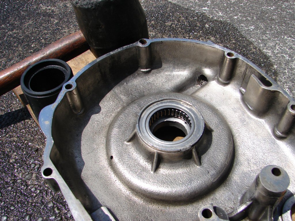
The pullrod that operates the clutch passes through the centre of the cush drive/rear sprocket, then passes through the outer cover into an adjustment area. There are a radial thrust bearing, a matching thrust washer and a needle roller bearing inbetween the two areas. Except on this bike. The outer main needle roller bearing which supports the cush drive assembly is missing.!
It should be inside the cavity behind the thrust washer.
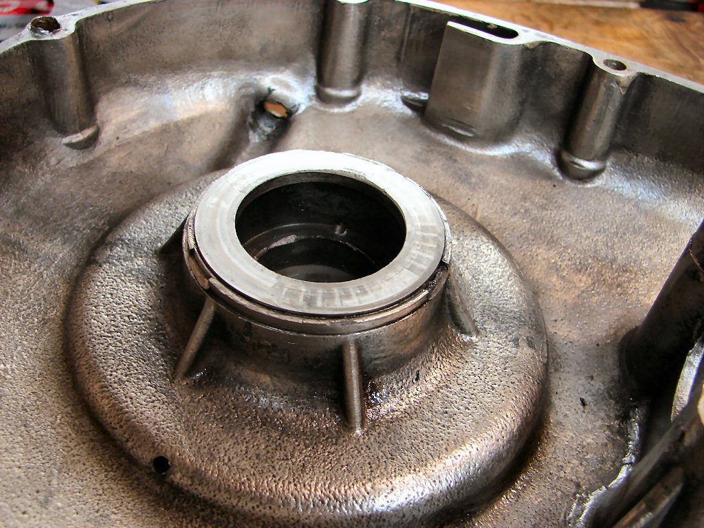
This vital bearing supports the entire rotating mass of the primary drive, and I cannot even imagine the mayhem that would have occurred in here if the bike had ever run like this. The bearing would have to have been sacrificed during the chrome plating process, but nobody ever put one back in, despite having to refit the thrust washer over the recess. As it happened I had a new one in my stock, but despite pouring boiling water over the case and leaving the bearing in the deep freeze for half an hour I could not convince the bearing to even begin entering its new home. I do not see any chrome plating within the cavity, but without a proper drift I risk damaging the new bearing, as needle rollers are not made of the same sturdy material as a roller/ball bearing.
I shall give it another try using a gas flame, but if it still refuses it will need Glen's attention.
This engine is fast approaching 'dog' category considering all the remedial work it has needed above and beyond a normal rebuild.
Light relief today in the form of making and installing a wiring loom. It began yesterday by removing the coil plate and drilling a few extra holes in it for cable ties to live in, as well as a couple of p-clips through which extra wires can be added or removed without disturbing other wiring.
Working from my wiring diagram I then made the loom and began fitting it in place from the headstock end, attaching all the wires to zener diode and switches while making sure it was all happy with full lock in both directions.
After attaching the main loom all the way rearwards it joined up with the Trispark, oil pressure switch, engine earth and alternator wires at the leading edge of the coil plate and then ran around the outer edge of that and through the two p-clips.
Next will be to terminate all these wires at the rectifier, relays and coils. The main battery leads will also be made up with a main fuse in the positive earth lead - simply because it came with red wires. I hope to fit a pair of LEDs somewhere on the plate to display the state of the relays as a user friendly feature.
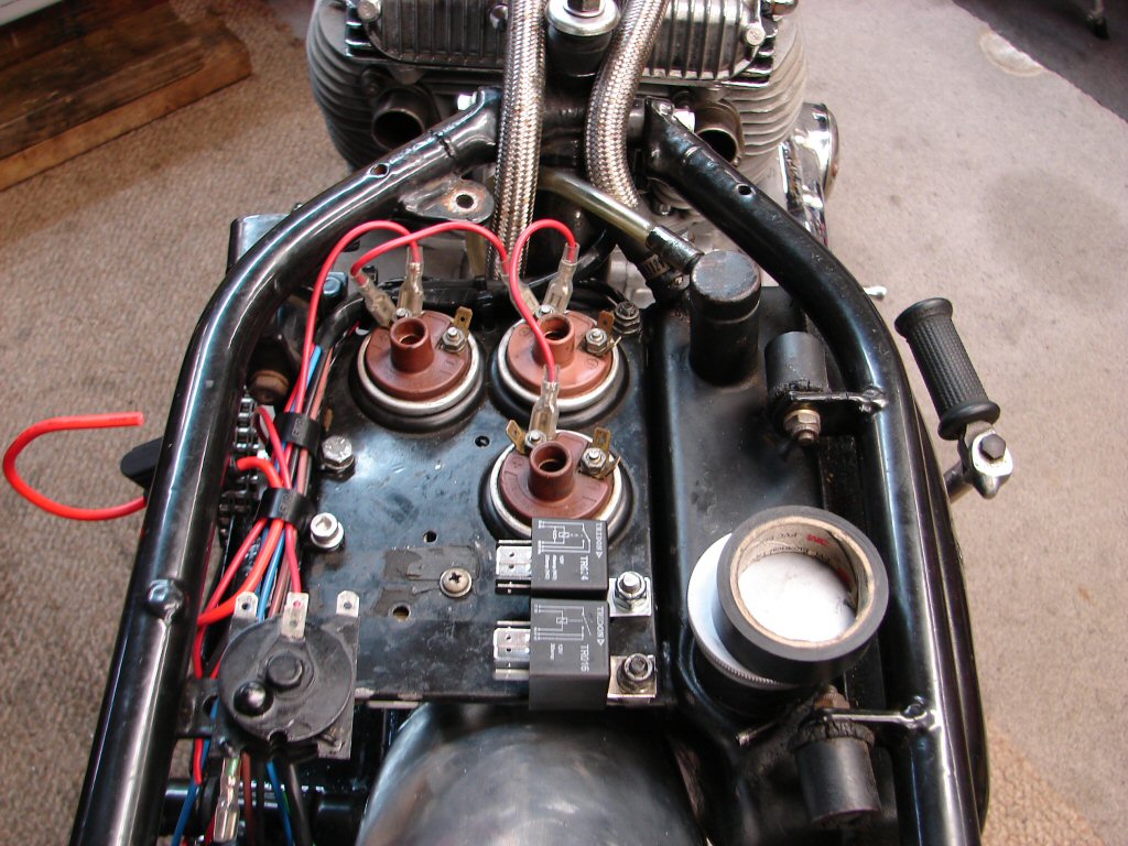
Wiring now complete apart from LED pilot lights for which a couple more holes will need to be drilled. While I had made a detailed wiring diagram, the majority of the connections were all on the two relays, but having identified the need for LEDs to be able to quickly see what state the relays were in I had to modify the original wiring plan.
Each relay will have its own LED, but the two relays are interlocked so one can override the other, and there was going to be a situation whereby one relay could remain powered when the main ON/OFF switch was turned off, so there was a revision. I will need to redraw the wiring diagram so it stays 100% accurate.
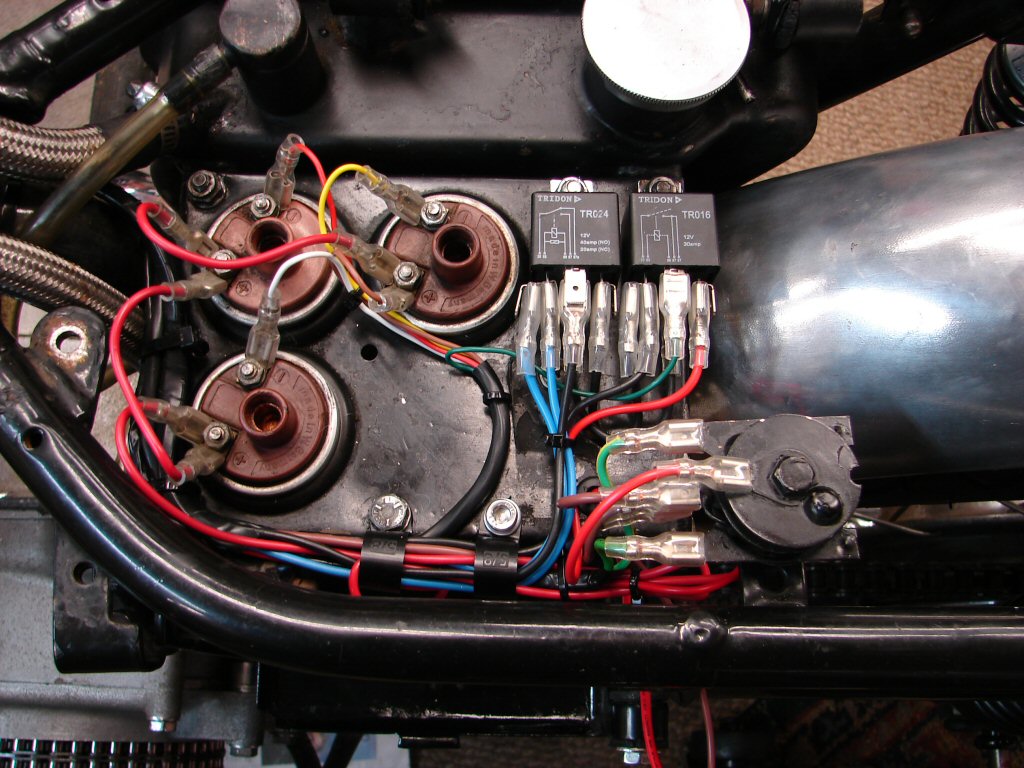
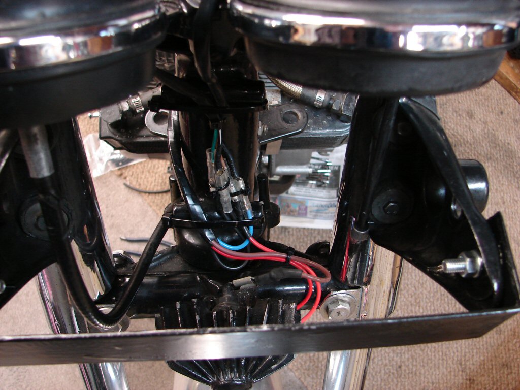
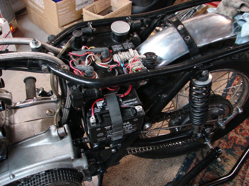
LEDs now fitted and wired, battery installed along with retaining strap, all functions tested and working as intended, oil pressure switch wiring disconnected for testing so the red LED is visible because the lanyard of the dead man switch is not present.
Subsequent to this test I reconnected the oil pressure switch and fitted the lanyard, gave the engine two kicks and the green LED came on indicating that the ignition was now on as all necessary conditions were met. It took about 30 seconds before the LEDs reverted to red so we have excellent oil pressure and bearings.
I had left the Trispark disconnected until we get spark plugs, as it can be harmful to the ignition if the coils cannot discharge via producing sparks. The required plugs are NGK BPR8ES, so they have the same centre electrode projection as Champion which gets the spark out of the plug thread area and into the combustion chamber. The 'R' means resistor, necessary for the Trispark as a form of suppression to avoid RF interference.
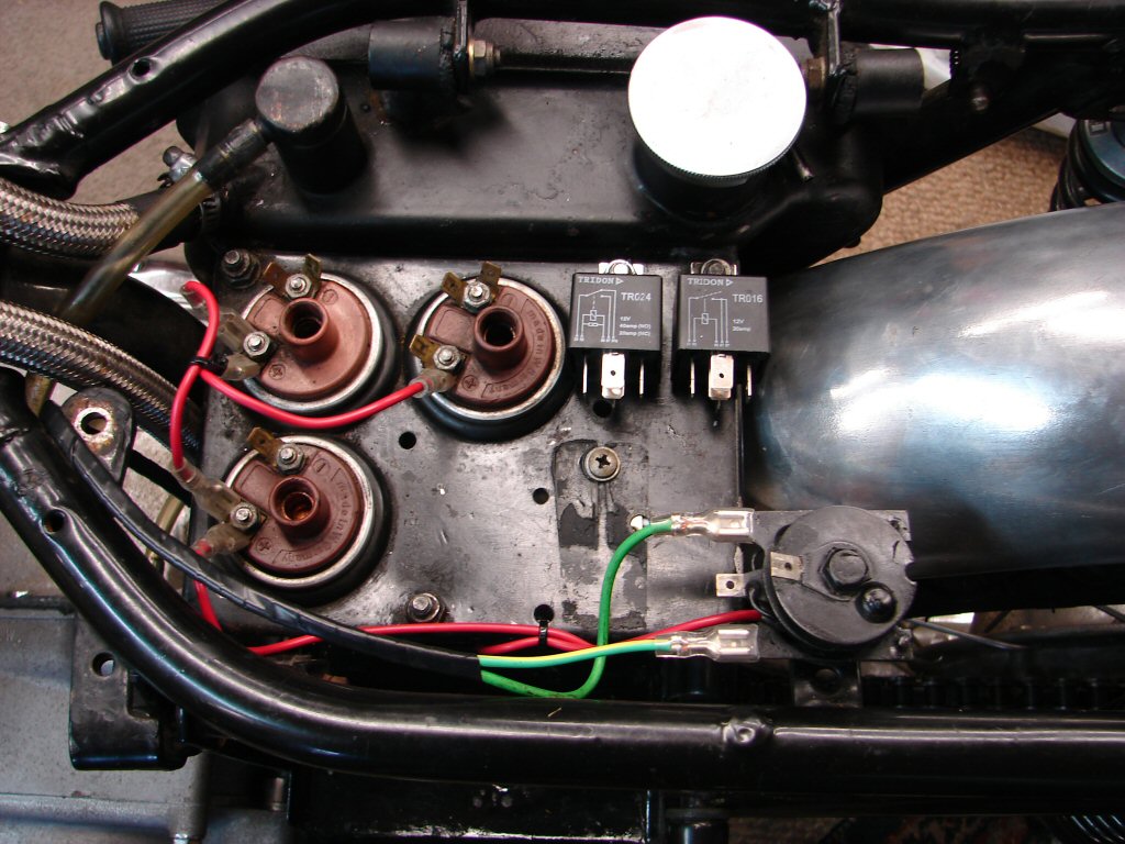
Green LED now on, and as the seat lifts from the right side both LEDs will be easily visible and will convey the status of the ignition setup at a glance.
The brown wire sitting next to the positive terminal on the top right coil is the feed to the Trispark, so is easily disconnectable when running any tests. As the green LED is connected to the negative feed of the Trispark it will always mimic the proper status of the Trispark whether it is connected or not.
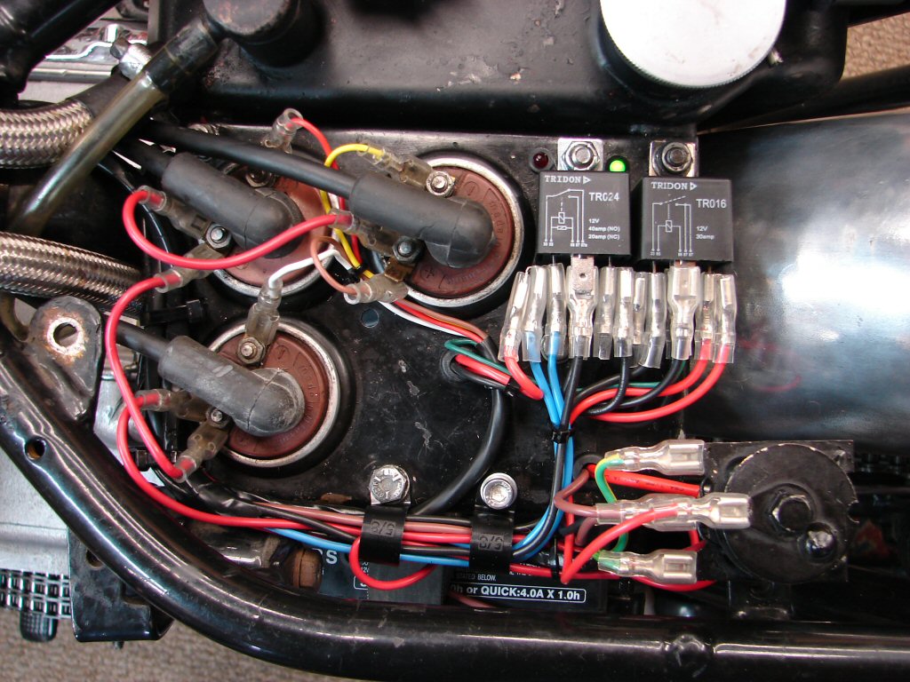
Here we see the master switch ON and the dead man lanyard in place courtesy of its magnet, which means the rider is presumably aboard so the switch is in OFF mode and the ignition is allowed to be ON.
This sort of situation is called 'reverse logic' where something needs to be off for something else to be on. It can tie your head in knots if you don't have a diagram to wire from. So I do.
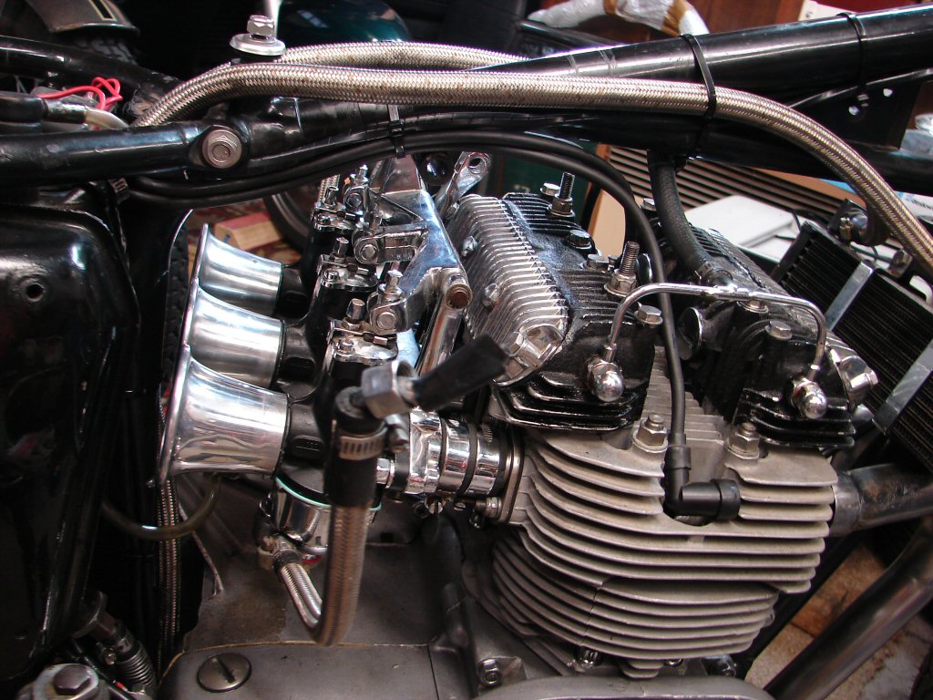
With wiring complete and AOK I added the fuel lines to the carbs and fitted them up with a bit of necessary trimming of the rubber intake hoses to move the carbs as far forward as possible. While I dislike the aeroquip style fuel lines they are entirely serviceable so I decided they could stay. I trust they pass scrutineering without comment.
The reason for ensuring the carbs were as close the head as possible was to allow the maximum breathing space around the intake ends of the velocity stacks we have decided to feature. As a general rule extending the inlet tract seems to suit these old British engines well.
It is always a journey of discovery when fitting parts that have never been used on any particular machine before, and what with having to wire from scratch as well as re-fettle some questionable previous bits, the time factor has stretched out to considerably longer than a stock rebuild.
'Discovery' often turns out to be a tad negative, so the new headers fouled the oil cooler at first try. In this photo the left side header is on the exhaust stub but the near side can go no higher than we see it.
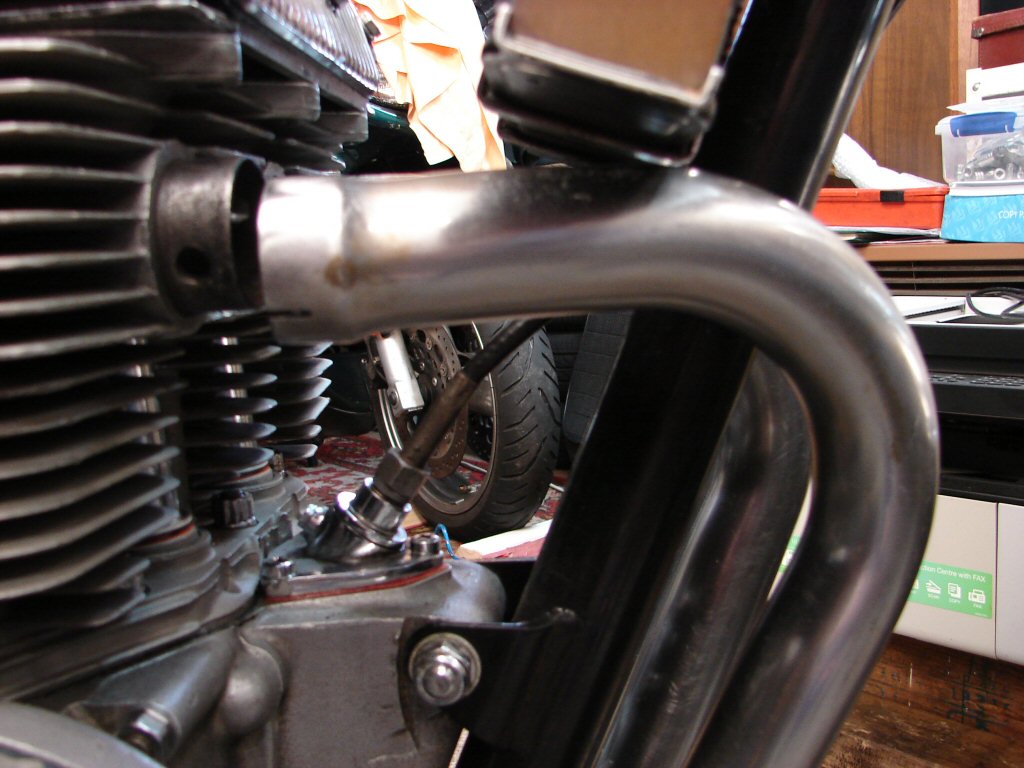
Looking at the shape of things I decided that perhaps when the headers were all fully engaged on the stubs, the curve of the pipes might just allow the cooler to co-exist, so I loosened the tank mounting bracketry and swung the cooler back and upwards, which indeed allowed fitting the system.
With the pipes in place I put the tank bracket back to find that there was the merest clearance between the two assemblies, but at least they were there. I shall open up the cooler mounting holes to see if I can gain just a slight airgap.
Meanwhile I added the fuel tank and muffler to get an idea of where we were up to.
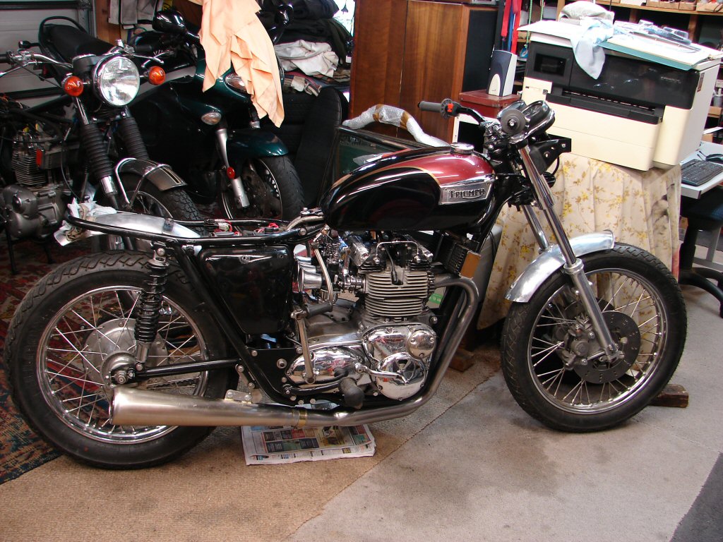
The low height of the muffler makes it look like a dirt tracker, and the owner was disappointed by the look. I was disappointed too, as the muffler precludes the use of the paddock stand, so I agree that something needs to be done.
My idea would be to get an intermediate piece of pipe fabricated with a good bend, thus moving the muffler rearwards with its exit location being somewhat above and rear of the axle, thus looking more like a factory racing exhaust. With the large diameter of the pipes I do not think some extra length would be an adverse tuning effect, and the increased height would enable the paddock stand which will be most necessary when the sidestand is removed. The muffler mounting could then be accommodated by use of the original pillion peg/muffler mounting plates.
More like this...
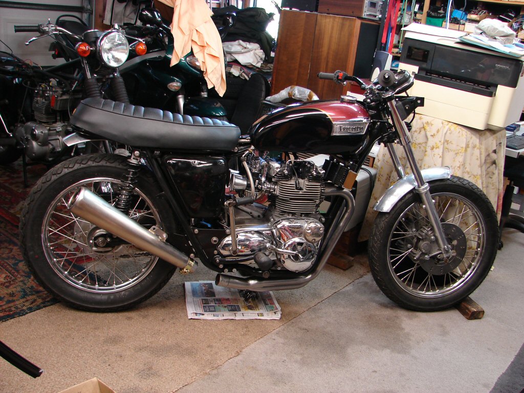
I lashed up what is at least a starting point for the final copy. The serious angle of rake is necessary to clear various limitations plus meet the requirements above. It is likely the bike can be taken to a suitable pipe smoker to get an adaptor made to fill in the gap, so having the muffler sitting mostly in place will be the picture worth the thousand words.
Although I envisaged there being a bit less rake I find it more exciting to look at than the original setup. It is also more user-friendly to the bloke behind you on the grid...
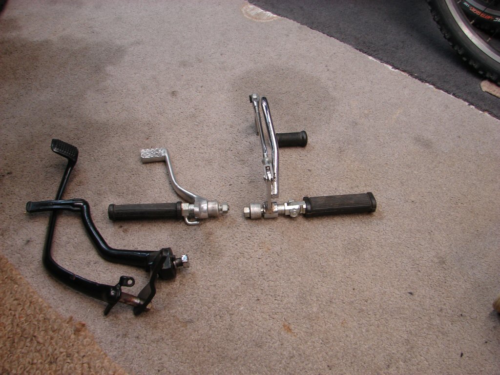
The optional rearset pegs were a great idea but have a number of engineering obstacles to overcome, which means I shall be refitting the original footpegs and levers at least in the short term. The spline for the gearlever shaft is too small suggesting that these were likely made for fitting to a twin.
The brake lever would need some trickery to actually operate the rod-operated rear brake, but more to the point is that the brake pedal fouls the primary drive cover, which is currently missing in action while the needle roller bearing gets fitted by someone with a bigger flamethrower than me.
In other work the chainguard got refitted, which was not the straightforward job I was expecting due to the wide rear tyre and the wide rear shocks conspiring to leave no room to get the thing inserted. The rear shock had to come off eventually, after which it all went in swimmingly well. The rear mounting hole needed opening up to clear what is now the paddock stand bobbin.
While I do not know, I suspect that the chainguard would be a scrutineering necessity, but I for one would not feel safe without one anyway. To use rodeo speak - it is a metal lasso just waiting to snaffle an unsuspecting calf... droll.
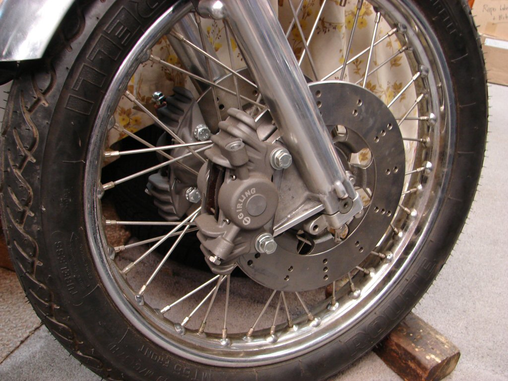
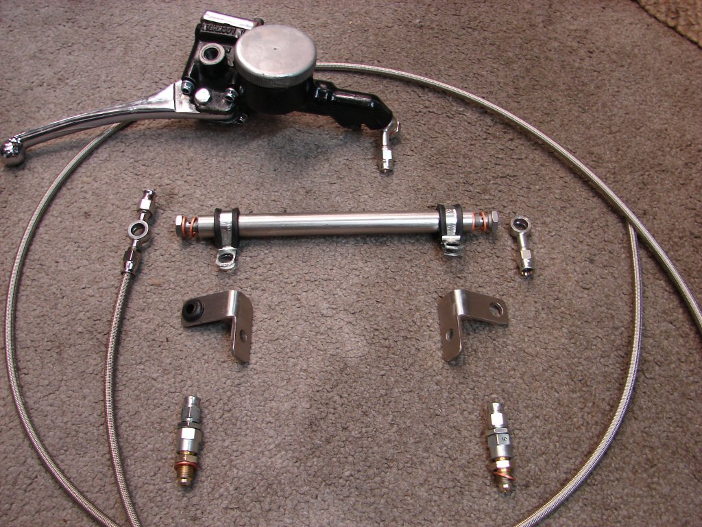
Concurrently moves are being made to organise ways of connecting the supplied Norton Commando brake master cylinder with these Girling alloy calipers, looking not unlike my own AP Lockheed period jobs. One of the most attractive things about the twin disk setup used to be that a pair of alloy calipers only weighed about the same as one original cast iron job. Have not yet checked to see if that still applies. There is of course still the weight penalty of one extra disk, but the resulting improvement in braking makes all other factors fade into insignificance. While proving a vast benefit on the highway, I think these would be an absolute necessity on the track.
Much measuring and comparing of fittings has been underway in order to try and copy the L P Williams 'Legend' setup I have on my T160, and the first step is to find if some local enterprise can make up the aeroquip lines for us. As I have another mate who is converting a T160 to twin disk we shall make two sets of everything, including the balance pipe which runs across the rear of the lower triple clamp and enables the two lower fluid lines to be identical. Thanks to their construction these type of lines do not swell in use, so minimising the penalty of having to move twice as much fluid as a single setup.
Who else loves brakes...?
Yeah, right.
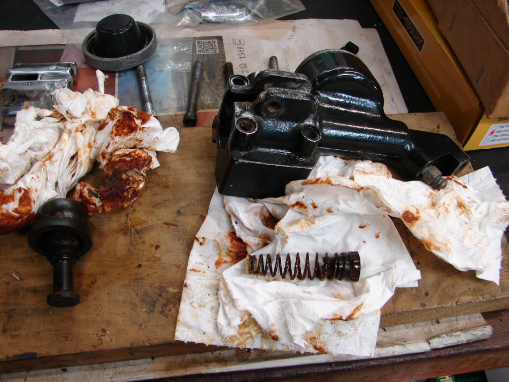
The usual tomato soup mix and it seems that this cylinder was last used with one seal missing, which may be why it was leaking out the lever end. The four mounting allen screws were so tight that I thought they had captive threads in the housing, but no, just an extra layer of chrome and four missing nuts. At least the piston and other bits came out freely despite the rust.
Happily the cylinder bore seemed to have avoided some of the risk of corrosion due to the missing seal being one less restriction, so hopefully it will behave itself now it has two.
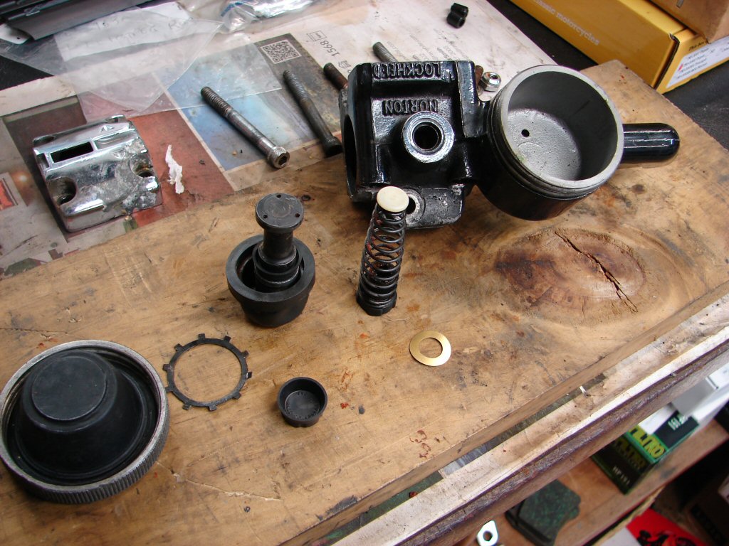
All these assemblies look so innocent when they are cleaned up and ready to go back together. Not a hint of the drama inbetween...
Once complete I poured a small amount of fluid into the reservoir and pumped it around. This will keep the seals moist while it awaits some lines to the calipers.
Finally a trial fit.
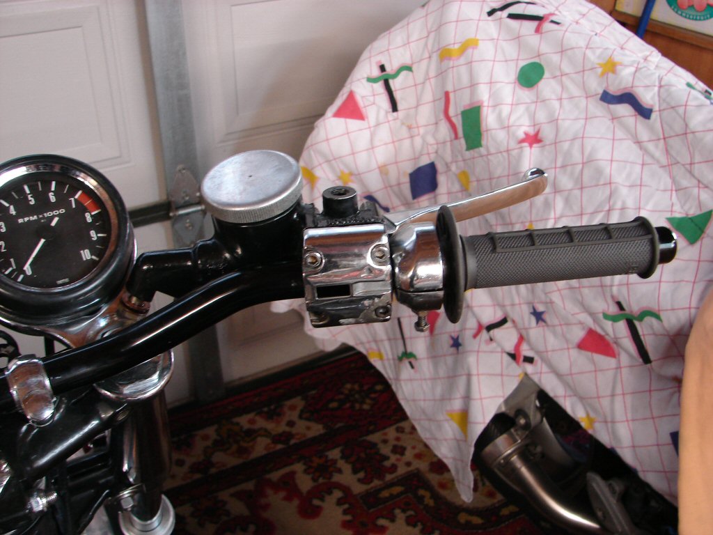
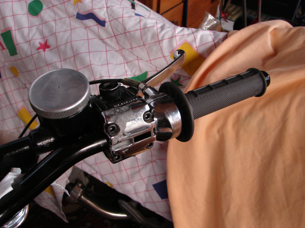
I try hard to arrange the throttle cable with the least possible number of bends, usually by having the cable exit the twistgrip horizontally forward across the top of the brake lever. No such luck here as there is a throttle friction device inside the housing which has a captive bolt that fouls the brake lever.
These parts were never designed to work together, and unsurprisingly - they don't, but I will likely rip some innards out if it convinces them to conform to my grand design.!
I win.!
Was able to forcibly remove the friction thing and we now have normal trajectory - although the cable adjuster at the carb end is stripped so we need a new cable.
Glen reported that the interference fit between bearing and recess in the primary cover was .004", which is probably twice what it should be, but his honing device would not fit inside the recess, and his milling machine could not handle a minimum skim of only .001" which is all that is needed - being .001" from the circumference of the circle.
I figured that it had indeed gotten plated, in which case there was only a thin coating, and I should be able to clean it up by hand, so I relieved him of the problem and set about it with various grades of emery paper. It surrendered much sooner than I thought it would and the grey matte look was replaced by shiny alloy.
Once I could just get one edge of the bearing to at least feel like it might go in I would repeat my boiling water treatment of the alloy cover while freezing the bearing. I also found that a mate's fork seal fitting drift would both locate the bearing while being pushed in, but by reversing it a rubber mallett could also be used to persuade without fear of harm.
We have a plan.
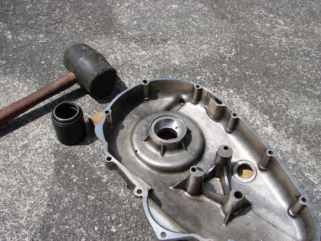
The plan worked beyond my expectations, and the bearing went about 1/3 the way in just pushing by hand, after which the drift and mallett only took half a dozen blows to get the bearing nicely flush with the outer edge.
Kilroy = 1, cover = 0.
Fantastic. Not only but also, the thrust washer afterwards went in with a mild tap or two and responded nicely to a bit of peening to prevent it rotating - which it obviously had been at some former time. Possibly without a bearing...
I gave the completed cover a bit of a polish up, laid a greased gasket on it and fitted it up to the inner. Everything seemed snug enough, and the gark I had spotted at the front edge looked as though it had a good chance of sealing. As it would also be above the oil level I figured it was worth the risk.
The clutch bits got reassembled and adjusted to my satisfaction, with only the need for another abutment where the cable enters, as someone had drilled the end of the current one out so far that the cable ferrule went right inside it, which just is not the idea. Now we have a perfectly compliant clutch action too.
I then put the required 350ml of oil inside the case and adjusted the chain tension. It feels as though the dominos just went my way today.
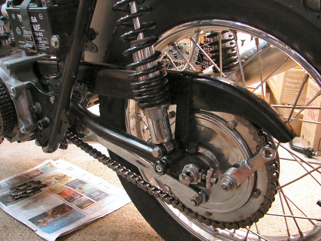
Still basking in the glow of yesterdays rapid progress, I set about fitting the rear brake lever and associated linkages. I immediately struck problems which brought an echo to mind. 'These parts were never designed to work together'. The brake rod was fouling the chainguard at the front end, and the oversize Koni shock absorber at the rear. I figured I could introduce a small spacer between the rear chainguard mount and the swingarm which might create just enough clearance for things to co-exist happily.
It then occurred to me that if I moved the front chainguard mount to the inside rather than the outside of the front swingarm mount I could also create the needed space at the front.
Well - it was a good idea.
Turned out that the chainguard was being forced outwards by the new rear mudguard, which unlike the original, lacked the flattened section which allows for the chainguard, so these two were rubbing against each other as the swingarm operated. The shock absorber was also using more space, as was the large rear tyre, so everything was unable to move anywhere without causing another clearance issue.
There was only one approach that was going to fix it all, and that was to create the flat side on the mudguard, and to do that the battery tray would need to come out.
The chainguard needed some altering of the front mounting bracket in order to play ball, and while it was out I shaped the edge of the mudguard to suit that result. The slightly increased offset of the chainguard now elicited a noise when the wheel was rotated, but it was not the chain which was my first thought, the tyre was now rubbing against the inner side of the chainguard so that needed a little reshaping too.
When the chainguard went back in I did manage to fit a small spacer at the rear, and miraculously everything cleared everything else and we now have a working brake.
Phew.!
I am not happy with the drilled bolt acting as the lever pivot at the rear of the rod, mostly because it is smaller diameter than the hole in the brake arm so it moves to and fro, losing some effective travel of the pedal. I have ordered a replacement along with a throttle cable, and in timely fashion, the original throttle cable broke today while checking I had full clearance between the carb operating bits and the clutch cable.
With the battery tray back in place I resurrected the side cover and its badge, as it will restrain the battery from exiting under wartime conditions, and it does not interfere with the airflow to the left side velocity stack. The oil tank cover does impinge a bit, so the jury is still out on that side.
Two other small jobs followed - straightening the left footpeg before fitting a new rubber, and making some rubber washers to fit the oil cooler mounting so that it stays put at the upper limit of the travel I created by grinding bits off the mounting bracket.
The gearbox then got treated to a full measure of synthetic gear oil, which tends to make gear changing an even sweeter task.
The exhaust has been nicely modded to extend the headers, thus allowing the muffler to move back and down while clearing axle and paddock stand. It looks happy.
Having received a set of the spark plugs needed to please the Trispark I decided to connect them outside the motor so I could kick the engine over and eyeball all three sparks happening. It was actually too bright out in the sun to see if there were sparks or not, but a second test when back in a gloomy shed they were clearly visible. I might run a compression test before sticking them in the holes.
I was impressed once again by how long it took for the oil pressure switch to turn back on after a few kicks while spark testing. Well over 30 seconds even on a pretty warm day. Good news.
We are starting to look the business.
The new parts showed up, and also brought to light a compatibility issue between twistgrip and cable. The standard Triumph cable is needed in order to connect to everything properly at the carb end, but because the unknown origin twistgrip adds another adjuster into the mix, the inner cable is too short to accommodate it without holding half throttle instead of idle.
As it happened, I had a used Trident twistgrip on hand, so it got fitted so that a trial engine run would be possible. That all mated up properly and led to this.
After that first run the cylinder head got retensioned with noticeable results, thus the valve clearances got readjusted as well. The head steady went back on and the rocker box allen screws got cleaned and a smear of silicone sealant down their threads. As everything has now settled it should not need disturbing again.
The twistgrip shall be staying, so the grips got changed over, and some trimming of the grip versus the bar end protector clearance took place to give a nice clean return to idle action. The rear brake received its new pivot and has adjusted up well.
It was decided to order various brake line and fittings from L P Williams in the UK, after which the lines will be made up to exactly suit the bike. This introduces a delay due to shipping, so the only other work I can do is to run the bike again to strobe the timing and tune the carbs.
The brake parts finally arrived, enough for two bikes but this one will be first and thus the learning curve. As it happened, the other bike is a mate's T160 and he has some serious engineering skills, so I showed him a couple of missing pieces of the puzzle to see if he had suggestions. He did. "leave it with me..". So I did.
What came back from that discussion were the missing pieces - beautifully made from stainless steel - and they are what you would want if anybody ever made them. I did invent one other solution which was minor in comparison, a couple of stainless clamps with rubber inserts which would be part of the mounting arrangement.
I had decided a rough course of action for making up the braided lines, and as I had only a couple of inches of extra braided line there could be no mistakes, so the lines were going to be made up on each bike in their three sections to suit. The T160 has longer forks than the T150 so the two lines from manifold to calipers are different lengths on each bike.
The manifold mounts behind the lower triple clamp on the existing pinch bolts and a banjo each end has a line down to its respective caliper. The third line runs from the double banjo on the right side up to the master cylinder. The two support brackets mount on the rear bolt which holds the mudguard bracket to the fork slider, and these brackets have to be fitted to the line before the lower end gets connected to the caliper.
I have established the first connection between line and double banjo but not finally tightened it in case it needs to be rotated a bit. This type of line does not twist nor bend easily as the inner PTFE pipe is hard enough to resist any swelling from hydraulic pressure in use, and thus allows the original master cylinder to now operate two calipers without losing its efficiency or developing too much lever travel.
I decided to fit the master cylinder back on the bars as it would eventually give me the dimension of the third line. Strangely it would not fit on the bars in the position it was when I last had it there, and the banjo bolt was hitting the top cap of the fork stanchion where it used to be clear. I began to look around the tacho bracket and found that the fork stanchion had migrated up through the triple clamp by half an inch. Hmmm. The owner has been putting some miles on the engine - on a closed road (lol) - and it seems the fork has adjusted itself during the process. This needs to be discouraged immediately.!

Well, the more you look the more you find.
Removing the instrument mounts today revealed that both stanchions are above their correct height by differing amounts. The pinch bolts seem to be doing their job properly so it is possible they were set up this way previously. I had not given the front end much attention as it would get done along with the brakes, which is now.
I plucked the bars off so I could manipulate the stanchions, and in doing so found the usual mismatch of mounting parts that do not allow the clamps and bushes to do their job properly. That was an easy fix, but dropping the stanchions so that just the fork caps were above the triple clamp led to discovering that the instrument mounts needed a bit of panel beating, so all that got done before starting the brake lines.
Worth the effort though, and there had been an issue with stopping the clock mounts rotating because of them not being flat enough, so all that is sorted. As the clocks were out I also took the opportunity to blank off the holes in the bottom where the instrument lights once were. Should keep things drier.
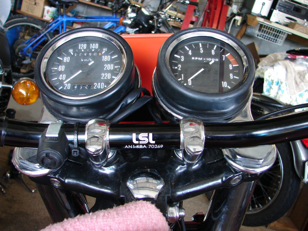
I started the brake line operation at the right side double banjo and worked down to the caliper. I figured that the banjo was going to determine the alignment of the fluid line, as there is no twisting these things. However, it turns out that the fittings at the caliper have the ability to swivel until finally pinched tight, so that made life easier.
I did the banjo joint then hung the line to mark where to cut it. I had decided to use a mini hacksaw to cut the line, and wound unsulation tape around it to try to keep the braid under control during the cut.
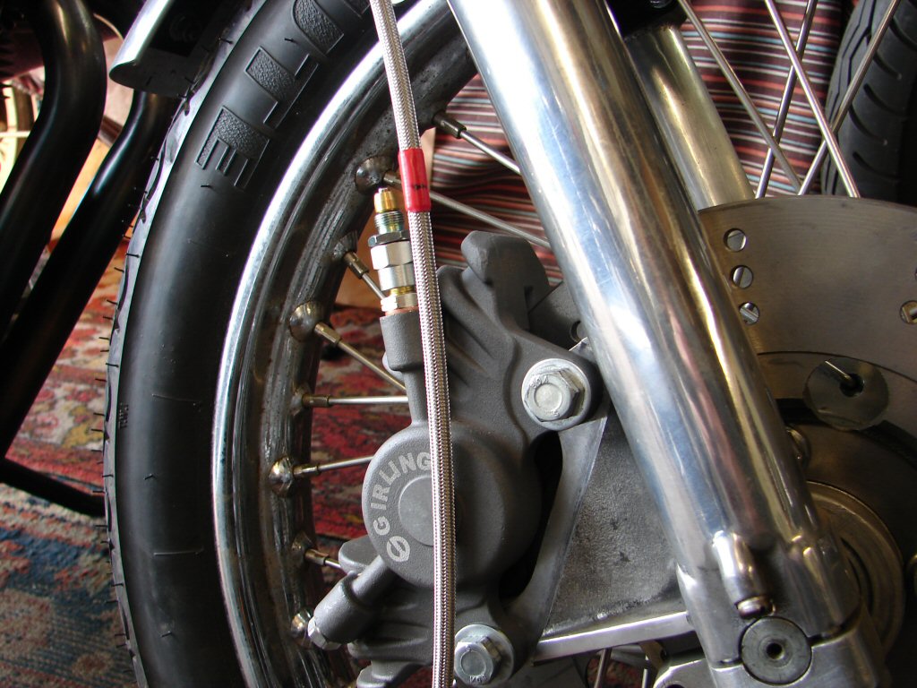
While the connections are quite fiddly they are not bad to work with, and the cut line was not hard to prepare for the next joint. I did decide that for the next cut I would use two layers of tape with a tiny gap for the hacksaw blade between, and this gave a better result.
I am glad that I had decided to do each line individually, as having made the right side I used the same method with the left and started at the banjo, then laid the lines out together to mark for the next cut. This led to the discovery that the two banjos had different length threaded pipes to the joint, so I actually saved some line length on the left side.
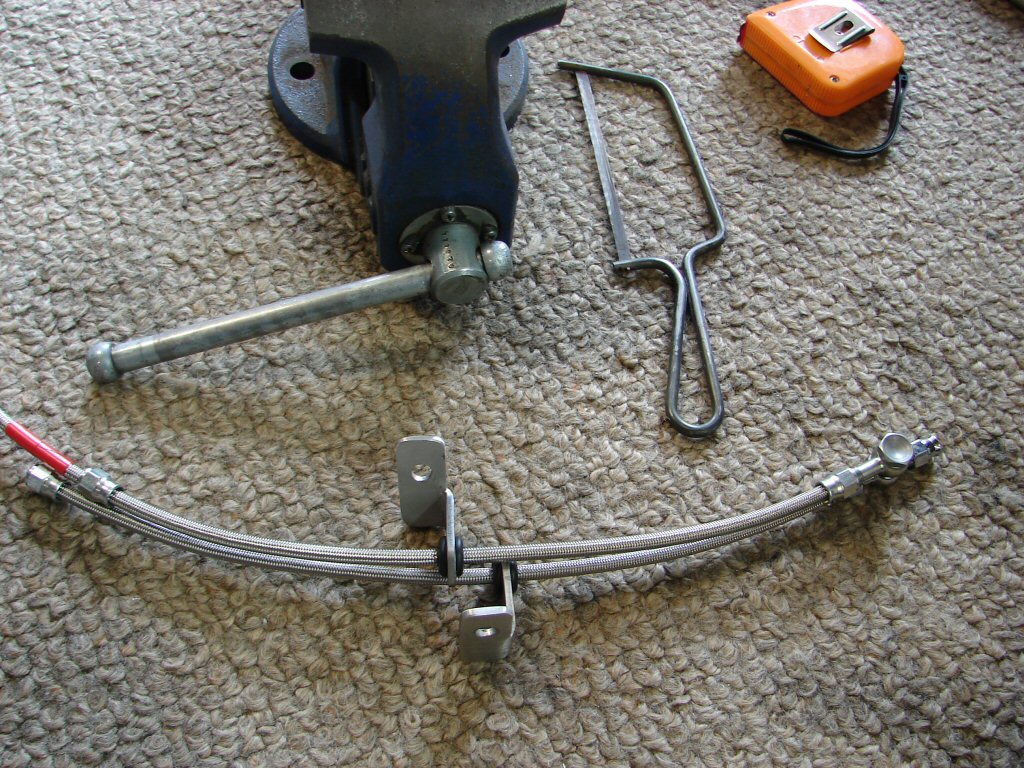
As can be seen, absolutely everything that needs to be on the lines has to go on at the very start, and that was one reason for using two bands of tape. I was able to leave the tape on the line after the cut until I had threaded everything on that needed to be there. I am still not sure how much tension should be used when tightening the joints, but as it needs to deform the olive which grips the PTFE pipe I figure it should be quite high.
When it came to the last line from the master cylinder I found that the position of the clocks obscured any route for the line within the headlight shrouds, so I ran it down the outside then used some spiral wrap to give it some protection from working against the chrome plating.
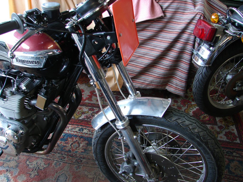
Apart from any fluid joining the plot yet the job seems to be complete and I am pleased that it worked out as I intended. The manifold and brackets were easy to install and they too have made the whole job much easier than some setups I have seen. I copied this arrangement from the parts that Les Williams used on his Legends and supplied me to fit to my bike long ago.
Might I say "elegant".?
The brakes bled up nicely and I was most pleased that the master cylinder was proven to be well up to the task, with a hard lever at half travel.
A brief test ride revealed that the brakes worked as well as they looked, although a hint of shudder under heavy front brakes led to a slight tightening of the steering head bearings which had never before had to handle such a degree of retarding speed quickly.
Better still, with the reassurance of now having some serious brakes it was possible to explore the performance a little. For a near standard power plant, with some weight loss, a large bore 3 into 1 and velocity stacks, this thing has some serious grunt. I would say that it performs considerably better than the sum total of its parts would suggest it should, and the delight of the noise it makes has you changing gears just for the howl.
I think that we have a great result, and I look forward to seeing it hit the track.